SolarEast PowerCool-LFP-HV Series User manual

版本:1.0Version: 1.0
PowerCool-LFP-HV series
Operation Manual
Jiangsu SolarEast Energy Storage Technology Co., Ltd

Disclaimer
Copyright © SolarEast Energy Storage Technology Co., Ltd. 2023. All rights reseed.
No pa of this document may be reproduced or transmitted in any form or by any means
without prior written consent of SolarEast Energy Storage Technology Co., Ltd.
The material furnished in this document is believed to be accurate and reliable. The informa-
tion and recommendations in this document do not constitute commitments or warranties in
the form of assignments. The information in this document is subject to change without
notice. You may refer to the ocial website (http://www.solareastess.com) for the most
updated version.
This document is intended only for the SolarEast PowerCool-LFP-HV batte system,
excluding the hybrid inveer or any other equipment. Please keep the Manual properly and
operate in strict accordance with all safety and operating instructions in this Manual. Please
do not operate the product before reading through the Manual.
All brands and product names are trademarks or registered trademarks of their respective
holders.
This Manual introduces PowerCool-LFP-HV manufactured by SolarEast. Please read this
manual before you install the product and follow the instructions carefully during the
installation process. Should you have any confusion, please contact SolarEast for advice and
clarication.

1. Introduction …………………………………………………………………………………… 1
1.1 Content and Structure of this Document ……………………………………………… 1
1.2 Target Group ……………………………………………………………………………… 1
1.3 Levels of Warning Messages ……………………………………………………………… 1
1.4 Denition of Abbreviations and Nouns ……………………………………………… 2
2. Safety ………………………………………………………………………………………… 2
2.1 Safety Instruction ………………………………………………………………………… 2
2.2 Batte precautions ………………………………………………………………………… 2
2.3 Emergency situation …………………………………………………………………… 3
3. System Introduction ………………………………………………………………………… 4
3.1 Specications ……………………………………………………………………………… 4
3.1.1 The parameter of system ……………………………………………………………… 4
3.1.2 Pack ………………………………………………………………………………………… 5
3.1.3 Batte Control Box …………………………………………………………………… 5
3.2 Application scenario………………………………………………………………………… 7
3.3 Features …………………………………………………………………………………… 7
4. Installation …………………………………………………………………………………… 7
4.1 Tools and safety gear …………………………………………………………………… 7
4.2 Package items ……………………………………………………………………………… 8
4.3 Installation location ………………………………………………………………………… 9
4.4 Module Installation ………………………………………………………………………… 9
4.5 Cables Connection …………………………………………………………………… 11
4.6 Power on ……………………………………………………………………………… 12
4.7 Power o ……………………………………………………………………………… 13
5. APP conguration and commissioning ……………………………………………… 13
6. Maintenance ………………………………………………………………………… 33
6.1 Capacity calibration …………………………………………………………………… 33
6.2 Annual inspection …………………………………………………………………… 33
1 . Introduction
1.1Content and Structure of this Document
This document is valid for PowerCool-LFP-HV batte system.
This document describes the product information, and guidance for installation, as well as APP
conguration and commissioning.
Obsee all documentation that accompanies the product, keep them in a convenient place
and available at all times.
Illustrations in this document are reduced to the essential information and may deviate from
the real product.
1.2 Target Group
This document is intended for qualied persons and end users. Only qualied persons are
allowed to peorm the operations marked with a warning symbol in this document. Tasks that
do not require any specic qualications will not be marked and can be peormed by the end
user. Qualied persons must have:
·Knowledge of working principle of Li-ion batte.
·Knowledge of how to deal with the dangers and risks associated with installing and using
electrical devices, batteries and systems.
·Knowledge of the installation and commissioning of electrical devices and systems.
·Knowledge of the applicable standards and directives.
·Understood and complied with this document, including all safety precautions.
·Understood and complied with the documents of the inveer manufacturer, all safety
precautions included.
1.3 Levels of Warning Messages
DANGER
DANGER indicates a hazardous situation which, if not avoided, will result in death or
serious inju.
WARNING
WARNING indicates a hazardous situation which, if not avoided, could result in death
or serious inju.
CAUTION
CAUTION indicates a hazardous situation which, if not avoided, could result in minor
or moderate inju.
CONTENTS
1

1.1Content and Structure of this Document
This document is valid for PowerCool-LFP-HV batte system.
conguration and commissioning.
Obsee all documentation that accompanies the product, keep them in a convenient place
and available at all times.
Illustrations in this document are reduced to the essential information and may deviate from
the real product.
1.2 Target Group
This document is intended for qualied persons and end users. Only qualied persons are
allowed to peorm the operations marked with a warning symbol in this document. Tasks that
do not require any specic qualications will not be marked and can be peormed by the end
user. Qualied persons must have:
·Knowledge of working principle of Li-ion batte.
·Knowledge of how to deal with the dangers and risks associated with installing and using
electrical devices, batteries and systems.
·Knowledge of the installation and commissioning of electrical devices and systems.
·Knowledge of the applicable standards and directives.
·Understood and complied with this document, including all safety precautions.
·Understood and complied with the documents of the inveer manufacturer, all safety
precautions included.
1.3 Levels of Warning Messages
DANGER indicates a hazardous situation which, if not avoided, will result in death or
serious inju.
WARNING indicates a hazardous situation which, if not avoided, could result in death
or serious inju.
CAUTION indicates a hazardous situation which, if not avoided, could result in minor
or moderate inju.
2 . Safety
2.1Safety Instruction
This product is designed and tested in accordance with international safety requirements IEC
62619, IEC 63056, and IEC 62040, but as with all electrical and electronic equipment, ceain
precautions must be obseed when installing and operating the product. To reduce the risk of
personal inju and ensure the safe installation and operation of the product, more attention
should be paid on following all instructions, cautions and warnings in this Manual.
2.2 Batte precautions
WARNING
It is impoant and necessa to read the user manual carefully before installing or
using batte. Failure to do so or to follow any of the instructions or warnings in this
document can result in electrical shock, serious inju, or death, or can damage
batte, potentially rendering it inoperable. ·If the batte is stored for long time, it is required to charge it eve six months, and the recom-
mended SOC should be 50%~55%. The batte shall not be stored for more than 12 months if the
storage temperature is -10 ~ 25℃, not more than 6 months if the storage temperature is 25 ~ 35
℃ and not more than 3 months if the storage temperature is 35 ~ 50℃
·Batte needs to be recharged within 12 hours after being fully discharged.
·Do not have the product installed in any environment that falls outside the range of tempera-
ture or humidity set out in the Manual.
·Do not expose cable outside.
·Do not connect power terminal reversely.
·All the power terminals must be disconnected for maintenance.
·Please contact the supplier within 24 hours in case of anything abnormal.
·Do not use cleaning solvents to clean batte.
·Do not expose batte to ammable or harsh chemicals or vapors.
·Do not paint any pa of batte, include any internal or external components.
·Do not connect batte with PV solar wiring directly.
·Any foreign object is prohibited to inse into any pa of batte.
The warranty claims are excluded for direct or indirect damage due to above
2.3 Emergency situation
DANGER
This product is designed with multiple safety strategies to prevent hazards resulting
from failure. However, hazards and dangers could emerge in few unceain situations.
2.3.1 Fire
The batte pack may catch re when heated over 150°C.
Ensure an ABC or carbon dioxide extinguisher nearby the batte, and do not use water to
extinguish the re.
If a re breaks out where the batte is installed, peorm the following actions:
·Extinguish the re before the batte catches re.
·If the batte has caught re, do not t to extinguish the re. The red batte will produce
poisonous gases, please evacuate people immediately.
2.3.2 Leaking
If the batte pack leaks, avoid contact with the leaking liquid or gas.
Electrolyte is corrosive and contact may cause skin irritation and chemical burns. If one is exposed
to the leaked substance, peorm the following actions:
Inhalation: Evacuate the contaminated area and seek medical attention immediately.
NOTICE
NOTICE indicates a situation which, if not avoided, can result in propey damage.
AC
APP
BAT
BMS
DC
INV
PV
SOC
SOH
alternating current
application
batte
batte management system
direct current
inveer
photovoltaic
state of charge
state of health
Abbreviation Noun
Warning electric shock.
Warning Fire.
Do not place near open ame.
Do not reverse connect the positive and negative.
Do not place at the children or pet touchable area.
23
1.4 Denition of Abbreviations and Nouns

Eyes contact: Rinse eyes with owing water for 15 minutes and seek medical attention immedi-
ately.
Skin contact: Wash the aected area thoroughly with soap and water and seek medical attention
immediately.
Ingestion: Induce vomiting as soon as possible and seek medical attention immediately.
2.3.3 Wet batte
If the batte is wet or submerged in water, do not t to access it. Contact customer seice for
technical assistance.
2.3.4 Damaged batte
Damaged batte may emit toxic gas or/and ammable gas, which could cause hazards to lives
or propey. If the batte is damaged, please keep away from the batte and contact customer
seice for help as soon as possible.
3. System Introduction
3.1 Specications
3.1.1 Parameters of system
3.1.2 Pack
3.1.3 Batte Control Box
Batte Cell Technology
Number of Pack(pcs)
Total energy(kWh)
Usable Energy*(kWh)
Voltage Range(Vd.c)
Nominal Voltage(V)
Max. Charge Voltage(V)
Max. continuous charging current(A)
Max. continuous discharge current(A)
DOD(%)
Communication
Dimension(L*W*H),mm)
Net Weight(kg)
Operating Condition
Humidity
Cooling type
WIFI Frequency Range
WIFI Maximum Transmission Power
IP rating of enclosure
Installation method
Supply connection
50
50
95
CAN/RS485
Indoor or outdoor
0~50 ℃
-10~50 ℃
<60%RH (No Condensation)
Natural
2412MHz~2472MHz
20dBm
IP55
Stacked installation
Fixed power cord
(720±2)*
(420±2)*
(616±3)
Operating
Temperature
Charging
Discharging
(116±3) (163±5) (210±7) (257±9) (304±11) (351±13)
(720±2)*
(420±2)*
(766±5)
(720±2)*
(420±2)*
(916±7)
(720±2)*
(420±2)*
(1066±9)
(720±2)*
(420±2)*
(1216±11)
(720±2)*
(420±2)*
(1366±1)
2
10.44
9.8
89.6~115.2
102.4
115.2
3
15.66
14.7
134.4~172.8
153.6
172.8
4
20.88
19.6
179.2~230.4
204.8
230.4
5
26.11
24.5
224.0~288.0
256.0
288.0
6
31.33
29.4
268.8~345.6
307.2
345.6
7
36.55
34.3
313.6~403.2
358.4
403.2
Li-iron (LFP)
Warranty
Authentication Level
10 years (5 free warranty + 5 paid warranty)
IEC62619�2022, including IEC60730-1,EN IEC 61000-6-1�2019,EN IEC
61000-6-3�2021,EN IEC 61000-3-2�2019/A1�2021,
EN 61000-3-3�2013/A2�2021,EN 301 489-1 V2.2.3,Draft EN 301 489-17
V3.2.5,EN 300 328 V2.2.2,EN 50663�2017,IEC62040
EN 62311�2008,IEC60529,IEC60068-2-52�2017,UN38.3/MSDS
* Testing conditions based on temperature 25℃ at the beginning of life. Total Energy/Usable Energy are measured with a
standard test method: 0.2C Charge and Discharge. As per the characteristics of lithium batteries, such parameters as the
charge/ discharge current and eciency listed above are subject to change. The nal right of interpretation is reseed by
Jiangsu SolarEast Energy Storage Technology Co., Ltd.
Batte Module Type
Total energy
Usable Energy*
Voltage Range
Nominal Voltage
Max. Charge Voltage
Max.continuous charging current
Max.continuous discharge current
DOD
Dimension(L*W*H)
Net Weight
Operating Condition
Operating Temperature
Humidity
Conguration
Warranty
PowerCool-LFP-HV
5.22 kWh
4.9 kWh
44.8~57.6 Vd.c
51.2 V
57.6 V
50 A
50 A
95%
(720±2)*(420±2)*(174±3)mm
(47±2)kg
Indoor or outdoor
0~50 ℃
-10~50 ℃
<60%RH (No Condensation)
(8S)2S
10 years (5 free warranty + 5 paid warranty)
Charging
Discharging
4 5

3.3 Features
·The batte is non-toxic, pollution-free and environmental-friendly.
·Anode material is made from LiFePO4 with safety peormance and long cycle life.
·Suppo upgrade BMS software via APP.
·BMS has protection functions including over-discharge, over-charge, over-current and
high/low temperature.
·Flexible conguration, multiple batte modules can be connected in series to increase storage
energy.
·The product also suppos parallel connection up to 3 strings of 7 stacks of PowerCool-LFP-HV
batte via Power Po for a maximum capacity of 109.62kWh.
4 . Installation
4.1 Tools and safety gear
The displayed tools are recommended and could be used in the installation of batte or
batteries. And the safety gear should be worn correctly during installation.
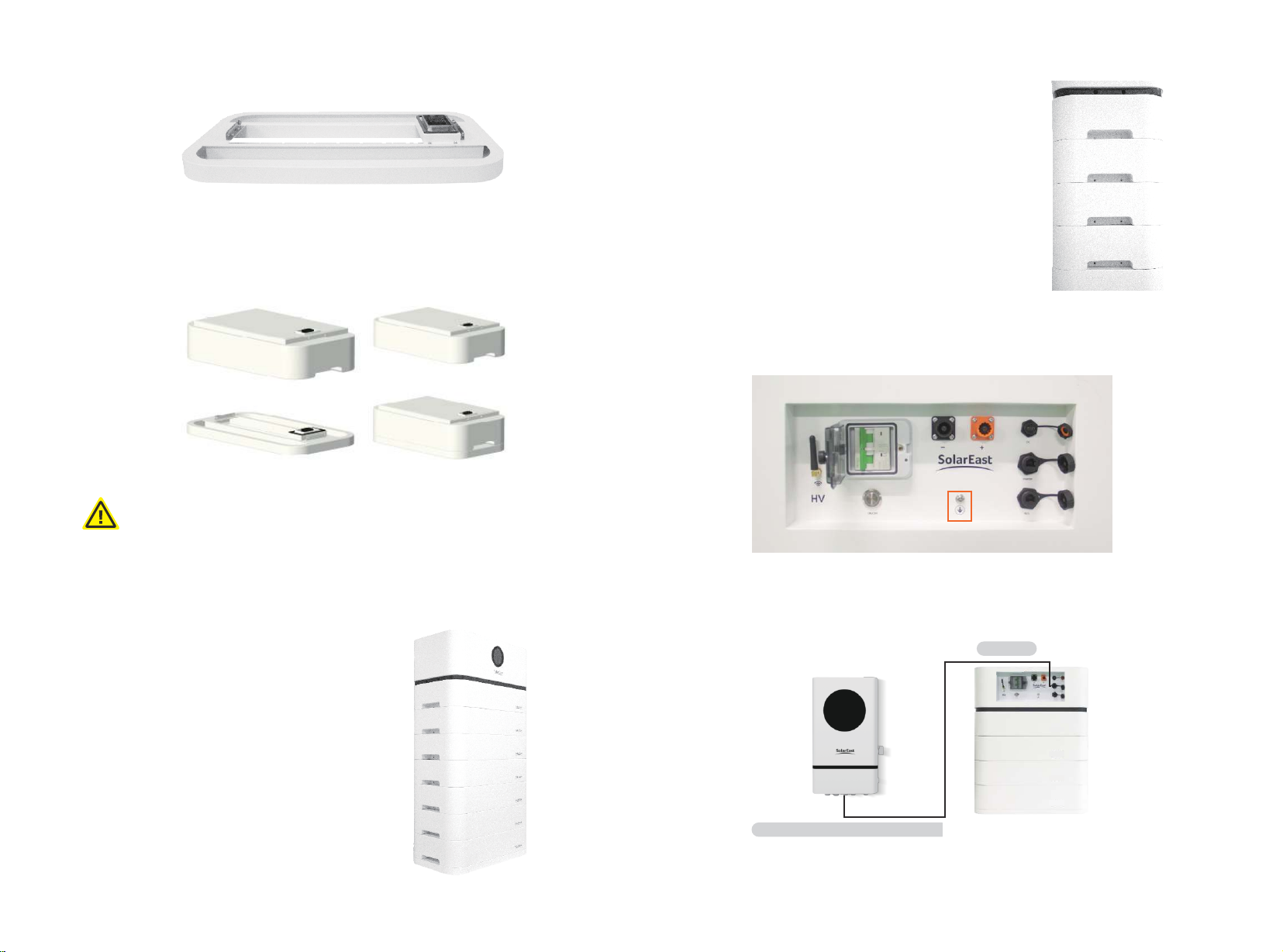
1) Batte Control Box Display Panel
2) Batte Control Box Inteace Panel
All pos are shown in the gure, and detailed information is shown in the table below
Object
1
2
3
4
5
6
7
8
Name
System SOC
No. of Packs
System Voltage
System Current
Monitor Button
WIFI Reset
Warning
WIFI
Description
--
--
--
--
Click to activate/deactivate
the monitor screen
--
If WiFi is to be reconnected, press the button
and hold for 5s till the WIFI icon on the screen
ashes, and then proceed with WiFi connection
on App by following the procedures set out in
Section 5.17 and 5.21 below.
This icon pops out on the screen in case of
system fault. Review and check the cause(s) of
the fault on APP
Object
A
B
C
D
E
F
G
H
I
Name
ON/OFF
Breaker
GND
DC
Inveer
M/S
WIFI Antenna
BAT+
BAT-
1: In case of fault, e.g., overcharge, over-discharge, overcurrent, and over-temperature, the red light will keep on
2: When batte system is under normal running, the green light will keep on
1
2
3
4
5
6
78
A C
D
F
E
G
HI
B
Batte system switch with indicators. When the Breaker is ON, sho press ON/OFF button for
2s to sta up the batte system and long press it for 3s to shut down the batte system
ON: main breaker ON, able to turn on batte system by ON/OFF button.
OFF: batte system turn o completely, no power output.
Power supply for the main controller, for commissioning by specialized personnel only
Communication po to inveer
Communication pos to parallel batteries
--
Batte anode
Batte cathode
Grounding protection
67
3.2 Application scenario

4.3 Installation location
Make sure that the installation location meets the following conditions:
·The oor is at and level;
·There are no ammable or explosive materials nearby;
·The ambient temperature is within the range from 0°C to 50°C;
·The temperature and humidity (<60%RH) are maintained at a constant level;
·There is minimal dust and di in the area.;
·The distance from heat source is more than 2 meters;
·The distance from air outlet of inveer is more than 0.5 meters;
·The installation areas shall avoid of direct sunlight;
·There are no mandato ventilation requirements for batte module, but please avoid of
installation in conned area. The aeration shall avoid of high salinity, humidity or temperature.
·According to the on-site situation, the equipment should be xed to the wall during installa-
tion against the wall.
·The batte system should be used in PD2 environment.
·Please install the batte system on a foundation about 30cm above the ground. Make sure a
distance of 20~30cm will be kept between the batte and the wall. The foundation shall bear a
load of 116~364kg.
4.4 Module Installation
1)Place the pedestal in the right place (the details about installation position described in
chapter 4.3)
CAUTION
If the ambient temperature is out of the operating range, the batte stops operating
to protect itself. The optimal temperature for the batte pack ranges from 10°C to
40°C. Frequent exposures to harsh temperatures may deteriorate the peormance
and life of the batte.
Screwdriver
Wire cutter
Crimping modular plier
Voltmeter
Pocket knife
Insulating tape
Insulated gloves
Safety goggles
Safety shoes
4.2 Package items
Batte Control Box
Item
1
2
3
4
5
6
7
8
PACK
1
2
Set
1
1
1
1
1
4
1
1
1
4
Description
Batte Control Box
Pedestal
2.5m power cable (4AWG) to inveer BAT+ po
2.5m power cable (4AWG) to inveer BAT- po
1m ground wire (5AWG)
M6*12 Pack connection screws
2.5m communication cable to inveer communication po
Operation Manual and Warranty Card
PACK
M6*12 Pack connection screws
30cm
20~30cm
89
2) Place batte pack in the right place of the pedestal. CAUTION: align the batte pack and
pedestal before putting it on, make sure the couplings are on the same line to avoid any structur-
al damage.
3) Stack batte packs (7 at most) on the pedestal
before placing the Batte Control Box on top of the
last batte pack.
4) Tighten M6*12 screws into the threaded holes
on both sides of Batte Control Box and each
pack.
4.5 Cables Connection
1) Connect the ground cable to the grounding point of the Batte Control Box.
2) Connect the communication cable by leading it from the inveer po of Batte Control Box
to the inveer BMS po.
CAUTION
Before placing batte pack or Batte Control Box on the pedestal, please align it
with the pedestal and make sure the couplings are on the same line to avoid any structural
damage or render installation impossible. Since each pack is as heavy as 47kg, if mechanical
tools are not available, it is recommended to have at least 2 workers working on batte
installation.
Inveer
Connect to the inveer BMS po
10 11

4.6 Power on
Check all the power cables and communication cables between Batte Control Box and inveer.
Check and make sure grounding is connected.
2) Turn on the Breaker on the Batte Control Box.
3) Switch ON the disconnection device between Batte Control Box and inveer if available.
4) Sho press for 2 sec the ON/OFF button, and then the ON/OFF button’s LED light (green) will
be on.
4.7 Power o
Press the ON/OFF button on the Batte Control Box and hold for 3 sec., and the ON/OFF
button’s LED light will be gradually o. Then disconnect the breaker.
5 . APP conguration and commissioning
5.1 Download our APP:
APP for iOS: Open up the APP Store, type in 'SolarEast PowerCool' in the Search tab to search and
download.
APP for Android: Open up the Google Play, type in 'SolarEast PowerCool' in the Search tab to
search and download.
You can also download our APP on our ocial website:https://www.solareastess.com.
5.2 Login page:
The main functions of this pages include language switching, password retrieval, registration,
login, viewing seice agreement and privacy agreement.
NOTICE
The PowerCool-LFP-HV batte system is designed to suppo both CAN and
RS485 communication with the inveer.
CAUTION
I.For Australian market, an overcurrent and disconnection device that isolates all live
conductors (positive and negative) is required between the batte system and the
inveer.
II.In Australia installations should be conducted in accordance with AS/NZS 3000
and AS/NZS 5139.
3) Connect BAT+ and BAT- power cables by leading them from Batte Control Box to
corresponding pos of inveer.
Connect to inveer BAT+,BAT-
BAT- BAT+
12 13
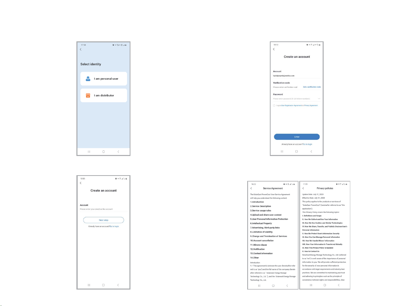
5.3 Click ‘Register’ and go to this page to select identity
5.4 Go to this page after selecting identity, inse the email address to be signed in and click
‘Next step’.
5.5 Click ‘get a verication code’ and retrieve it from the mailbox. Inse the verication code
received on this page, set the password, check ‘I agree’ and click ‘Enter’.
5.6 Click ‘Seice Agreement’ or ‘Privacy Agreement’, you may view the details of such agree-
ment.
14 15

5.7 Click to switch language
5.8 Click ‘Retrieve the password’ and go to this page, you may inse the account number, obtain
a verication code via email, input the verication code and click ‘Next step’.
5.9 On this page, you can reset password by inseing the new password twice, and then click
and go to the front page.
5.10 The picture demonstrates a distributor’s account.
It shows such gures as the number of devices installed, total installed capacity, newly increased
clients this month and total number of clients.
16 17

5.11 Click ‘System installed’ on the front page, you can view the systems you created. You may
search by system name, email or address.
5.12 On the ‘system list’ page, you may add new systems by clicking ‘+’ button. Then ll in
information as instructed and save.
5.13 Click any item on the system list, you will go to the ‘System information’ page, where you
may view and edit system information.
5.14 Click ‘Batte device’ on the ‘System information’ page and go to ‘Batte list’, where you
may add device and view batte information.
PowerCool-LFP-HV
PowerCool-LFP-HV
18 19

5.15 Click ‘+’ on the ‘Batte list’ page and then you may add a new device by scanning its tag
code.
5.16 Find our label code on the side of the device and scan it.
5.17 Scan tag code and go to ‘Add device’ page, and then click ‘Wireless connection’ for WIFI
conguration.
5.18 Click on "How to Add a Device" to view the step-by-step instructions for adding a device.
20 21
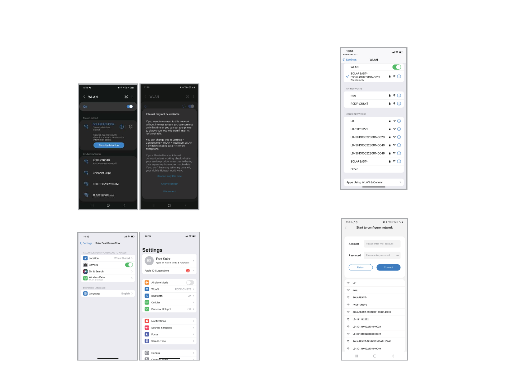
5.19 On the system WIFI page, you can nd the device WIFI name based on its SN code.
Device WIFI name: SOLAREAST-(device SN code)
Click ‘connect’ and then you are given the options of ‘Connect only this time’ and ‘Always connect’.
PS: When device WIFI has no network available, a prompt will pop out when a cellphone is connected to a WIFI
without network. Only after peorming the procedures above will the cellphone be truly connected to the
device WIFI.
5.19.1 Android Page Conguration
5.19.2 iOS Page Conguration
a) After entering the page, click on "Settings" to access the system settings page.
b) On this page, click on "Wireless LAN" to access the Wi-Fi conguration page and connect to
the device's Wi-Fi.
5.20 When the cellphone is truly connected to device WIFI, click ‘Return’ on the system WIFI
page of the APPP and it will jump to ‘Sta to congure network’ page.
You may then select a WIFI on the list and input its password, and click ‘Connect’.
22 23

5.21 When the network is successfully congured, a prompt will pop out.
Click ‘Bind device information’ button, and return to device list page when the binding is done.
5.22 Click any item on the batte list you will go to the device details page, where you can view
such data as batte SOC, batte temperature, voltage, power, current, operating information,
cell monitoring, alarm data and statistics.
5.23 You may check the operating information of the device and view the upgrade protocol.
5.24 View alarm data
24 25

5.25 View cell running data
5.26 [Distributor account]
‘My’ page features the following functions: checking personal information, viewing messages,
viewing installers, viewing clients, switching language, switching temperature unit, submitting
feedback and setting the system.
‘My seice’ mainly include viewing FAQ, operation manual, APP version information and suppli-
er’s information.
5.27 You are allowed to change avatar, name and contact on ‘Account settings’ page.
5.28 On ‘Installer management’ page, you may view installers under your name. Click each
installer to view the details.
26 27

5.29 You may view client details by clicking ‘Client management’. By clicking the system list, you
may view the system information.
5.30 Language and temperature unit switching
5.31 On this page you may repo problems encountered and view historical feedback.
5.32 On ‘FAQ’ page you may view the list of common alarm problems. Click any item to view
details.
28 29

5.33 View APP version details.
5.34 ‘About us’ pages shows company prole and contact information of the supplier.
5.35 On this page, you may change password or email address. You may also view list of shared
information, log o, view seice agreement and privacy agreement, clear cache and cookies,
and log out.
5.36 On ‘Account and security’ page, you may change password and email address.
30 31
+86-0518-80325812

5.37 On account cancellation page, you are allowed to cancel your account.
5.38 View alarm list and alarm description.
6.Maintenance
6.1 Capacity calibration
It is better to fully charge-discharge the batte for the capacity calibration at least once eve
six months (if available). Please conduct the calibration maintenance according to the following
steps:
1)Make sure there is a relatively stable power supply source to charge the batte at a maximum
charge current of 50A, e.g. grid.
2)Make sure the batte discharges through PCS at a maximum discharge current of 50 A.
3)Set the inveer, and ensure that the DOD is 100% (if available), the maximum charge current is
less than 50 A (20.4A is recommended), while the maximum discharge current is 50 A.
4)Adjust the inveer working mode and discharge the batte till power o, and keep it for at
least 30 min;
5)Adjust the inveer working mode and charge the batte to 100%, and keep it for at least 30
min;
6)Adjust the inveer working mode and discharge the batte till power o, and the capacity
calibration is nished;
7)Charge the batte to 30%~80%SOC, and then set the inveer as before the capacity calibra-
tion.
6.2 Annual inspection
Eve year after installation. The connection of power connectors, grounding points, power
cables and screws are to be checked. Make sure there is no loosening, fracture or corrosion at
any connection point. Check the installation environment such as dust, water, insect etc. and
make sure it is suitable for IP55 batte system.
PowerCool-LFP-HV
PowerCool-LFP-HV
PowerCool-LFP-HV
PowerCool-LFP-HV
32 33
Table of contents
Other SolarEast Storage manuals


