SolarEast PowerCool-LFP5000 Series User manual

PowerCool-LFP5000 series
Operation Manual
Version No.: V1.0
Jiangsu SolarEast Energy Storage Technology Co., Ltd

Jiangsu SolarEast Energy Storage Technology Co., Ltd
Disclaimer
Copyright © SolarEast Energy Storage Technology Co., Ltd. 2023. All rights
reserved.
No part of this document may be reproduced or transmitted in any form or by any
means without prior written consent of SolarEast Energy Storage Technology Co.,
Ltd.
The material furnished in this document is believed to be accurate and reliable. The
information and recommendations in this document do not constitute commitments or
warranties in the form of assignments. The information in this document is subject to
change without notice. You may refer to the official website
(http://www.solareastess.com) for the most updated version.
This document is intended only for the SolarEast Powercool-LFP5000 battery,
excluding the hybrid inverter or any other equipment. Please keep the Manual
properly and operate in strict accordance with all safety and operating instructions in
this Manual. Please do not operate the product before reading through the Manual.
All brands and product names are trademarks or registered trademarks of their
respective holders.
This Manual introduces PowerCool-LFP5000 from SolarEast. Please read this manual
before you install the product and follow the instructions carefully during the
installation process. Should you have any confusion, please contact SolarEast for
advice and clarification.

Jiangsu SolarEast Energy Storage Technology Co., Ltd
CONTENTS
1. Introduction ............................................................................................................1
1.1 Content and Structure of this Document ...................................................... 1
1.2 Target Group .................................................................................................1
1.3 Levels of Warning Messages ........................................................................1
1.4 Definition of Abbreviations and Nouns ....................................................... 2
2. Safety ..................................................................................................................... 3
2.1 Safety Instruction ......................................................................................... 3
2.2 Battery precautions .......................................................................................3
2.3 Emergency situation ..................................................................................... 4
3. Product Introduction .............................................................................................. 5
3.1 Technical Data ..............................................................................................5
3.2 Product Appearance ......................................................................................6
3.3 Battery Interface Instruction .........................................................................7
3.4 Application scenario .....................................................................................8
3.5 Features ........................................................................................................ 8
4. Installation ............................................................................................................. 9
4.1 Tools and safety gear ....................................................................................9
4.2 Package items ............................................................................................... 9
4.3 Installation location .................................................................................... 11
4.4 Installation direction ...................................................................................12
4.5 Bracket installation .....................................................................................12
4.6 Parallel connection ..................................................................................... 14
4.7 Connect to inverter ..................................................................................... 17
4.8 Power on .................................................................................................... 18
4.9 Power off .................................................................................................... 19
5. APP configuration and commissioning ............................................................... 19
6. Maintenance .........................................................................................................51
6.1 Capacity calibration ....................................................................................... 51
6.2 Annual inspection .......................................................................................... 51
Jiangsu SolarEast Energy Storage Technology Co., Ltd
1
1. Introduction
1.1 Content and Structure of this Document
This document is valid for Powercool-LFP5000 battery.
This document describes the product information, and guidance for installation, as
well as APP configuration and commissioning.
Observe all documentation that accompanies the product, keep them in a convenient
place and available at all times.
Illustrations in this document are reduced to the essential information and may deviate
from the real product.
1.2 Target Group
This document is intended for qualified persons and end users. Only qualified persons
are allowed to perform the operations marked with a warning symbol in this
document. Tasks that do not require any specific qualifications will not be marked and
can be performed by the end user. Qualified persons must have:
Knowledge of working principle of Li-ion battery.
Knowledge of how to deal with the dangers and risks associated with installing
and using electrical devices, batteries and systems.
Knowledge of the installation and commissioning of electrical devices and
systems.
Knowledge of the applicable standards and directives.
Understood and complied with this document, including all safety precautions.
Understood and complied with the documents of the inverter manufacturer, all
safety precautions included.
1.3 Levels of Warning Messages
DANGER
DANGER indicates a hazardous situation which, if not avoided, will result in death or
serious injury.
WARNING
WARNING indicates a hazardous situation which, if not avoided, could result in death
or serious injury.
Jiangsu SolarEast Energy Storage Technology Co., Ltd
2
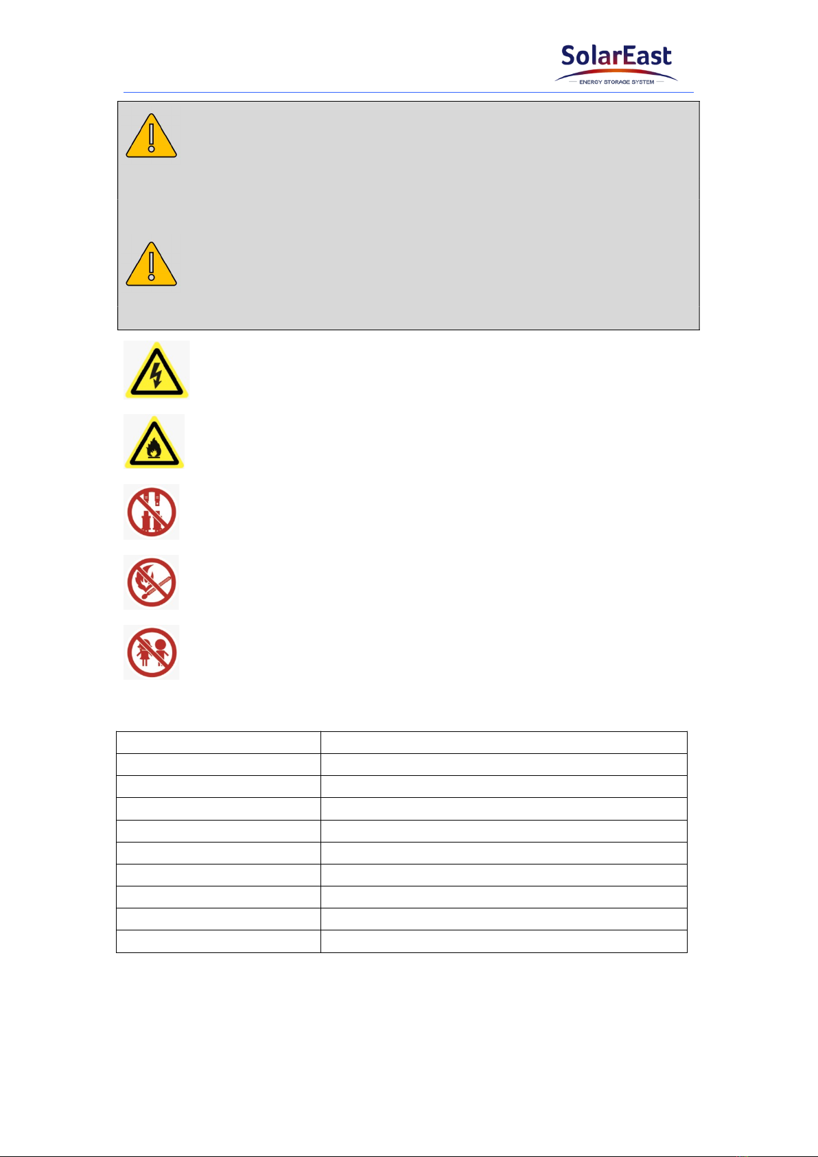
CAUTION
CAUTION indicates a hazardous situation which, if not avoided, could result in minor
or moderate injury.
NOTICE
NOTICE indicates a situation which, if not avoided, can result in property damage.
Warning electric shock.
Warning Fire.
Do not reverse connect the positive and negative.
Do not place near open flame.
Do not place at the children or pet touchable area.
1.4 Definition of Abbreviations and Nouns
Abbreviation Noun
AC alternating current
APP application
BAT battery
BMS battery management system
DC direct current
INV inverter
PV photovoltaic
SOC state of charge
SOH state of health

Jiangsu SolarEast Energy Storage Technology Co., Ltd
3
2. Safety
2.1 Safety Instruction
This product is designed and tested in accordance with international safety
requirements IEC 62619, IEC 63056, and IEC 62040, but as with all electrical and
electronic equipment, certain precautions must be observed when installing and
operating the product. To reduce the risk of personal injury and ensure the safe
installation and operation of the product, more attention should be paid on following
all instructions, cautions and warnings in this Manual.
2.2 Battery precautions
WARNING
It is important and necessary to read the user manual carefully before installing or using
battery. Failure to do so or to follow any of the instructions or warnings in this document
can result in electrical shock, serious injury, or death, or can damage battery, potentially
rendering it inoperable.
If the battery is stored for long time, it is required to charge it every six months,
and the recommended SOC should be 50%~55%. The battery shall not be stored
for more than 12 months if the storage temperature is -10 ~ 25℃, not more than 6
months if the storage temperature is 25 ~ 35℃ and not more than 3 months if the
storage temperature is 35 ~ 50℃
Battery needs to be recharged within 12 hours after being fully discharged.
Do not install the product in outdoor environment, or an environment out of the
operation temperature or humidity range listed in the Manual.
Do not expose cable outside.
Do not connect power terminal reversely.
All the power terminals must be disconnected for maintenance.
Please contact the supplier within 24 hours in case of anything abnormal.
Do not use cleaning solvents to clean battery.
Do not expose battery to flammable or harsh chemicals or vapors.
Do not paint any part of battery, include any internal or external components.
Do not connect battery with PV solar wiring directly.
Any foreign object is prohibited to insert into any part of battery.
The warranty claims are excluded for direct or indirect damage due to above

Jiangsu SolarEast Energy Storage Technology Co., Ltd
4
reasons.
2.3 Emergency situation
DANGER
This product is designed with multiple safety strategies to prevent hazards resulting from
failure. However, hazards and dangers could emerge in few uncertain situations.
2.3.1 Fire
The battery pack may catch fire when heated over 150°C.
Ensure an ABC or carbon dioxide extinguisher nearby the battery, and do not use
water to extinguish the fire.
If a fire breaks out where the battery is installed, perform the following actions:
Extinguish the fire before the battery catches fire.
If the battery has caught fire, do not try to extinguish the fire. The fired battery
will produce poisonous gases, please evacuate people immediately.
2.3.2 Leaking
If the battery pack leaks, avoid contact with the leaking liquid or gas.
Electrolyte is corrosive and contact may cause skin irritation and chemical burns. If
one is exposed to the leaked substance, perform the following actions:
Inhalation: Evacuate the contaminated area and seek medical attention immediately.
Eyes contact: Rinse eyes with flowing water for 15 minutes and seek medical
attention immediately.
Skin contact: Wash the affected area thoroughly with soap and water and seek medical
attention immediately.
Ingestion: Induce vomiting as soon as possible and seek medical attention
immediately.
2.3.3 Wet battery
If the battery is wet or submerged in water, do not try to access it. Contact customer
service for technical assistance.
2.3.4 Damaged battery
Damaged battery may emit toxic gas or/and flammable gas, which could cause
hazards to lives or property. If the battery is damaged, please keep away from the
battery and contact customer service for help as soon as possible.

Jiangsu SolarEast Energy Storage Technology Co., Ltd
5
3. Product Introduction
3.1 Technical Data
Model PowerCool-LFP5000
Total energy 5.22 kWh
Usable Energy* 4.9 kWh
Voltage Range 44.8~57.6 Vd.c
Nominal Voltage 51.2 V
Max. Charge Voltage 57.6 V
Max. continuous charging current 50 A
Max. continuous discharge current 80 A
DOD 95%
Communication CAN/RS485
Max. Number of Parallel 10
Dimension(L*W*H) (560±2)*(390±2)*(138±2)mm
Net Weight (45±1)kg
Operating Condition Indoor
Operating
Temperature
Charging 0~50 ℃
Discharging -10~50 ℃
Humidity <60%RH (No Condensation)
Cooling type Natural
WIFI Frequency Range 2412MHz~2472MHz
WIFI Maximum Transmission Power 20dBm
IP rating of enclosure IP20
Configuration (8S)2S
Installation method Rack mount
Supply connection Fixed power cord
Warranty 10 years (5 free warranty + 5
paid warranty)
Authentication Level
IEC62619/IEC63056/IEC62040
/ICE61000-6-1/3/
ICE61000-3-2/3
/UN38.3/MSDS
*Testing conditions based on temperature 25℃at the beginning of life. Total Energy/Usable Energy are

Jiangsu SolarEast Energy Storage Technology Co., Ltd
6
measured with a standard test method: 0.2C Charge and Discharge.
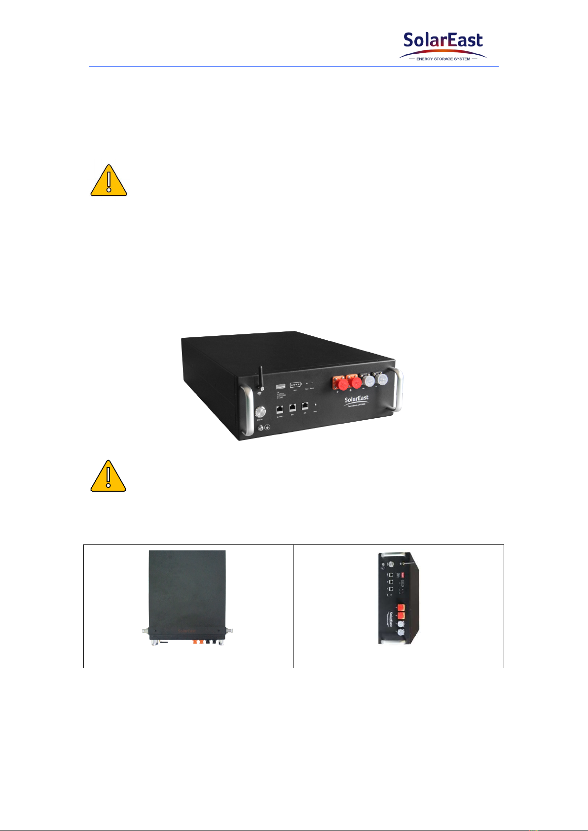
3.2 Product Appearance
Jiangsu SolarEast Energy Storage Technology Co., Ltd
7
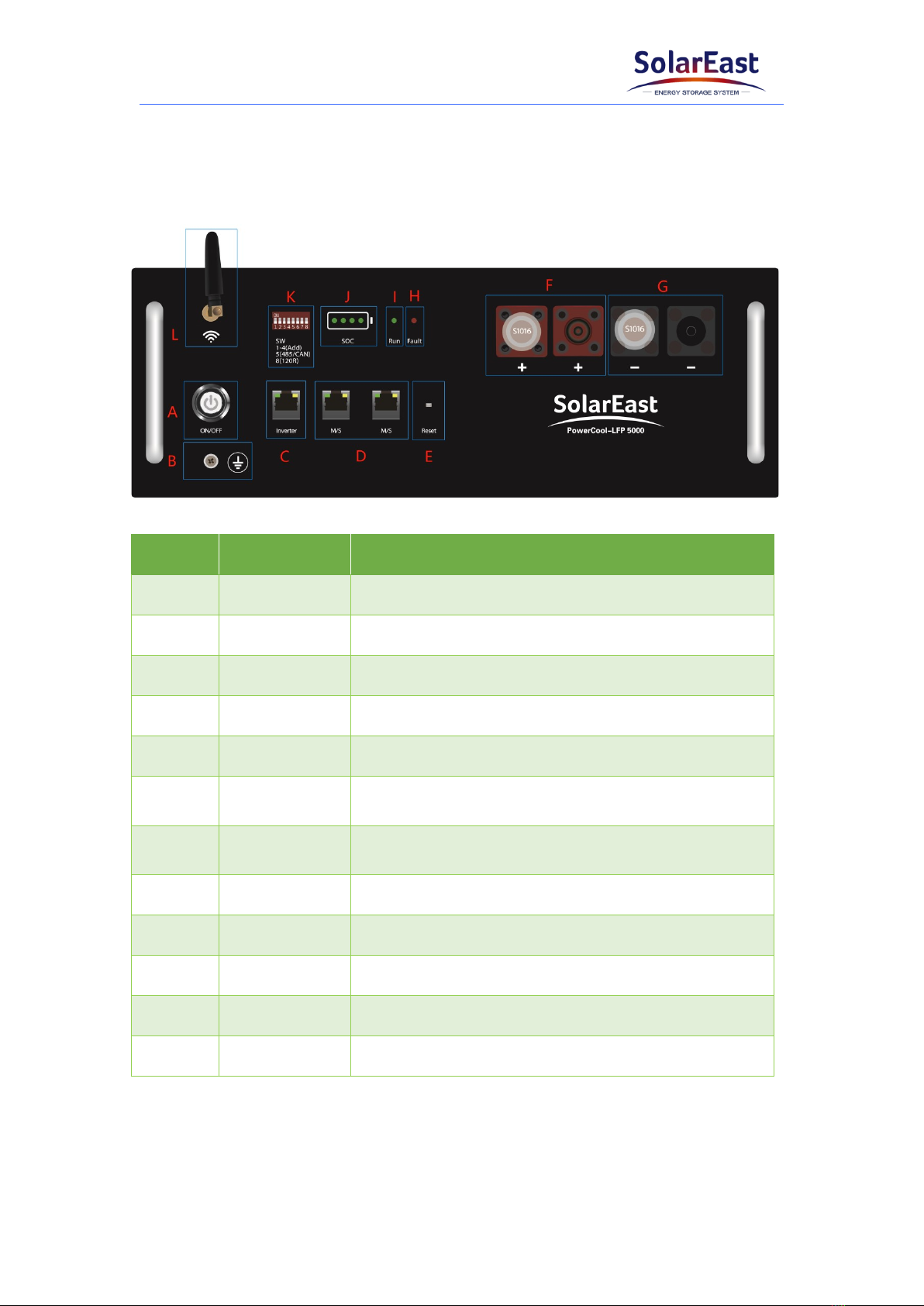
3.3 Battery Interface Instruction
All the ports and indicators are shown in the picture below and detailed in the
following table.
Object Name Description
APower switch The switch of the battery
BGND Grounding protection
CInverter Communication port to inverter
DM/S Communication ports to parallel batteries
EReset Reset the WIFI configuration
FBAT+ The left side is the input terminal; the right side is
the output terminal
GBAT- The right side is the input terminal; the left side is
the output terminal
HFault 1Fault indicator; Red light
IRun 2Operating indicator; Green light
JSOC SOC indicator light
KSW 3DIP switch
LWIFI Antenna --
1: The red light keeps flashing when fault occurs, such as overcharge, over-discharge,
overcurrent, as well as over high/low temperature, etc.
2: The green light flashes slowly when the battery runs normally. The green light
flashes quickly when turning on or off.
Jiangsu SolarEast Energy Storage Technology Co., Ltd
8
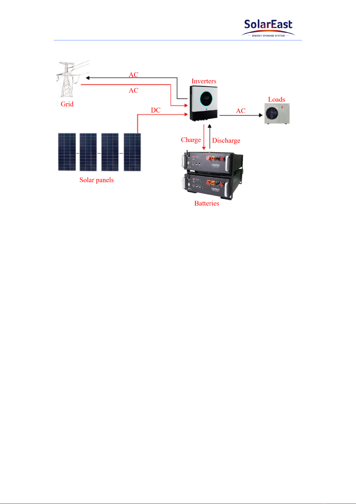
3.4 Application scenario
3.5 Features
The battery is non-toxic, pollution-free and environmental-friendly.
Anode material is made from LiFePO4with safety performance and long cycle
life.
Support upgrade BMS software via APP.
BMS has protection functions including over-discharge, over-charge, over-current
and high/low temperature.
Flexible configuration, multiple battery modules can be connected in parallel for
capacity expansion.

Jiangsu SolarEast Energy Storage Technology Co., Ltd
9
4. Installation
4.1 Tools and safety gear
The displayed tools are recommended and could be used in the installation of battery
or batteries. And the safety gear should be worn correctly during installation.
Screwdriver Wire cutter Crimping modular plier
Voltmeter Pocket knife Insulating tape
Insulated gloves Safety goggles Safety shoes
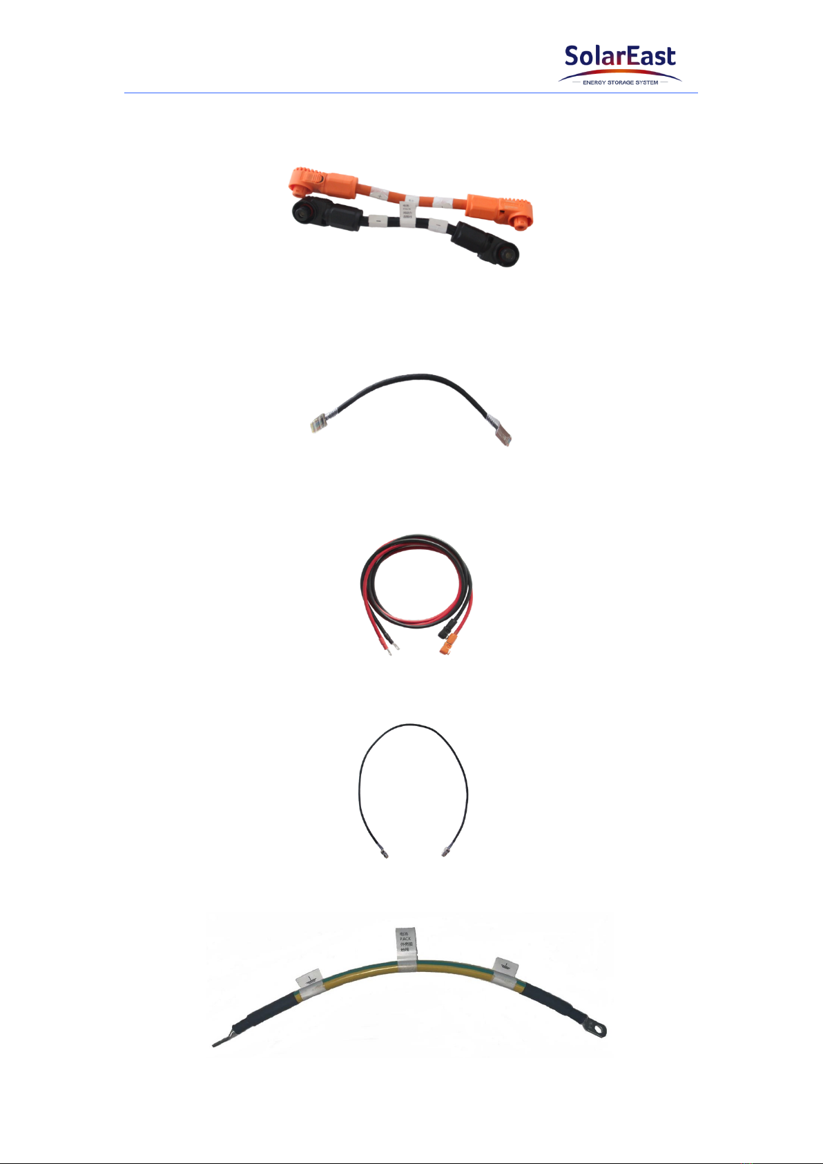
4.2 Package items
Multiple products can be connected in parallel to expand capacity, and the pack
connected to the inverter is the master while the others are slaves.
a. Battery pack*1
Jiangsu SolarEast Energy Storage Technology Co., Ltd
10
b. Parallel connection power cables*2 (Only for slaves, 4AWG)
c. RJ45 communication cable for parallel configuration*1 (Only for slaves)
d. Power cables to inverter*2 (Only for master)
e. RJ45 communication cable to inverter*1 (Only for master)
f. Ground wire (6AWG)
Jiangsu SolarEast Energy Storage Technology Co., Ltd
11
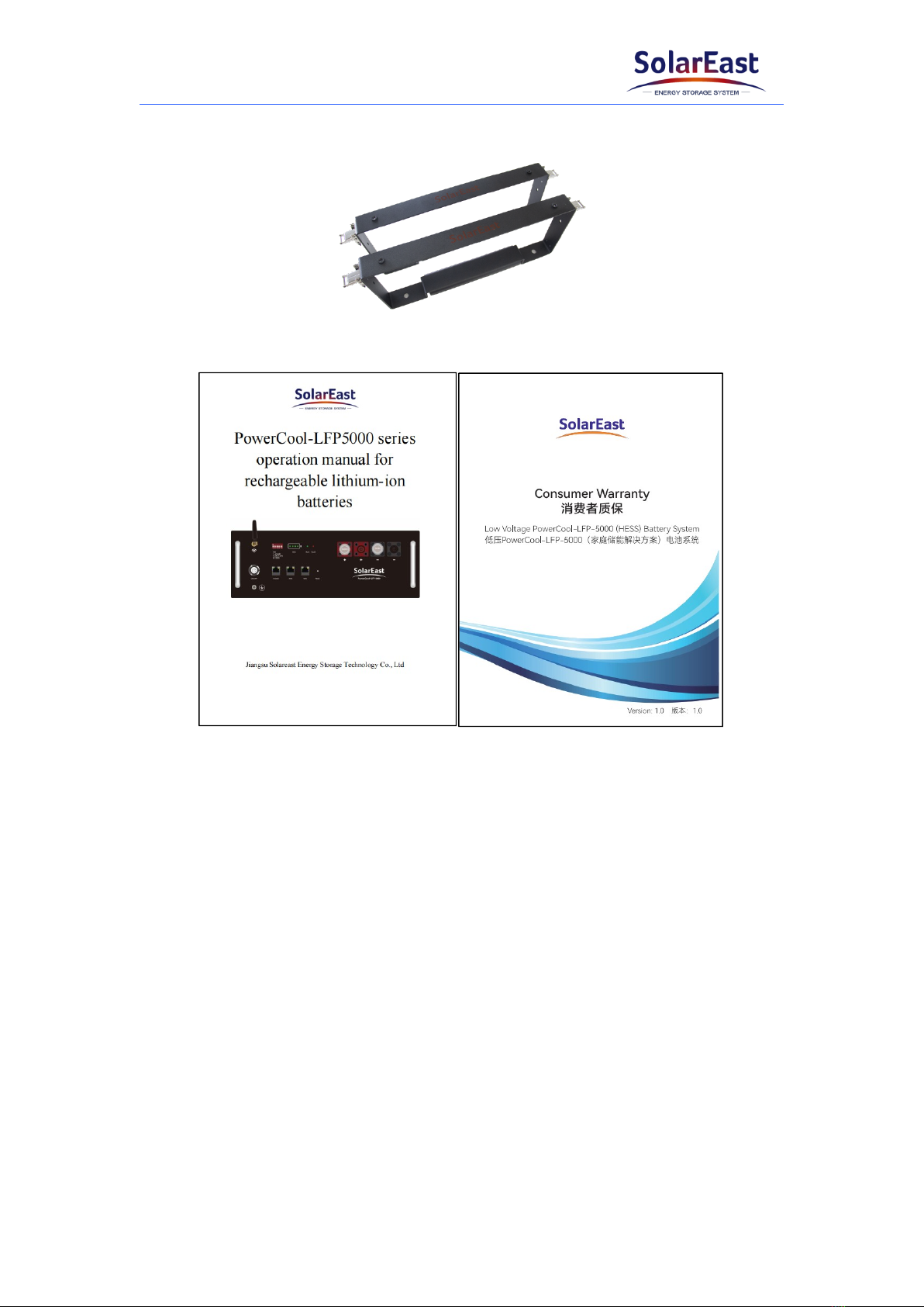
g. Bracket*2
h. User Manual & Warranty card *1
4.3 Installation location
Make sure that the installation location meets the following conditions:
The area is completely waterproof;
The floor is flat and level;
There are no flammable or explosive materials nearby;
The ambient temperature is within the range from 0°C to 50°C;
The temperature and humidity (<60%RH) are maintained at a constant level;
There is minimal dust and dirt in the area;
The distance from heat source is more than 2 meters;
The distance from air outlet of inverter is more than 0.5 meters;
The installation areas shall avoid of direct sunlight;
There are no mandatory ventilation requirements for battery module, but please
avoid of installation in confined area. The aeration shall avoid of high salinity,
Jiangsu SolarEast Energy Storage Technology Co., Ltd
12
humidity or temperature.
According to the on-site situation, the equipment should be fixed to the wall
during installation against the wall.
The battery system should be used in PD2 environment.
CAUTION
If the ambient temperature is out of the operating range, the battery stops operating to
protect itself. The optimal temperature for the battery pack ranges from 10°C to 40°C.
Frequent exposures to harsh temperatures may deteriorate the performance and life of
the battery.
4.4 Installation direction
Recommended:
NOTICE
Do not stack modules together directly.
Not allowed:
Upside down Sidelong
4.5 Bracket installation
1) Put the battery into 2 pcs of bracket.

Jiangsu SolarEast Energy Storage Technology Co., Ltd
13
2) Use 4 location holes, stack the batteries together.
3) And connect the 4 lockers together.
4) Maximum 5 in stack.

Jiangsu SolarEast Energy Storage Technology Co., Ltd
14
4.6 Parallel connection
1) Please check the voltage of each battery and make sure the voltage difference is
less than 1V.
2) Connect communication cables to M/S communication terminal interface between
batteries.
3) Connect the orange parallel connection power cables to the BAT+ terminals of
adjacent batteries.
4) Connect the black parallel connection power cables to the BAT- terminals of
adjacent batteries.
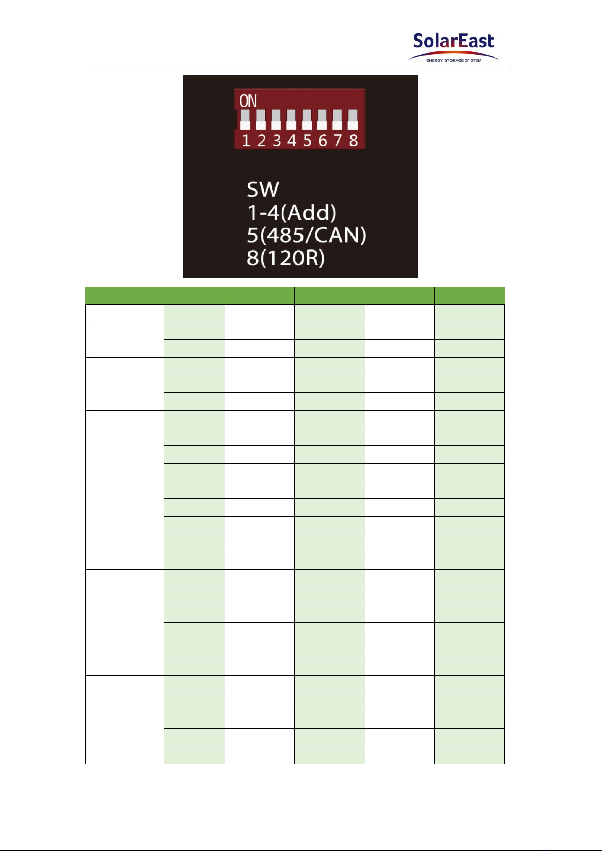
5) Select the batteries’ addresses by setting the DIP 1~4 on each battery, as shown in
the following Fig.
Jiangsu SolarEast Energy Storage Technology Co., Ltd
15
BAT number Group DIP 1 DIP 2 DIP 3 DIP 4
1- OFF OFF OFF OFF
2Master ON OFF OFF OFF
Slave OFF ON OFF OFF
3
Master ON OFF OFF OFF
Slave 1 OFF ON OFF OFF
Slave 2 ON ON OFF OFF
4
Master ON OFF OFF OFF
Slave 1 OFF ON OFF OFF
Slave 2 ON ON OFF OFF
Slave 3 OFF OFF ON OFF
5
Master ON OFF OFF OFF
Slave 1 OFF ON OFF OFF
Slave 2 ON ON OFF OFF
Slave 3 OFF OFF ON OFF
Slave 4 ON OFF ON OFF
6
Master ON OFF OFF OFF
Slave 1 OFF ON OFF OFF
Slave 2 ON ON OFF OFF
Slave 3 OFF OFF ON OFF
Slave 4 ON OFF ON OFF
Slave 5 OFF ON ON OFF
7
Master ON OFF OFF OFF
Slave 1 OFF ON OFF OFF
Slave 2 ON ON OFF OFF
Slave 3 OFF OFF ON OFF
Slave 4 ON OFF ON OFF

Jiangsu SolarEast Energy Storage Technology Co., Ltd
16
Slave 5 OFF ON ON OFF
Slave 6 ON ON ON OFF
8
Master ON OFF OFF OFF
Slave 1 OFF ON OFF OFF
Slave 2 ON ON OFF OFF
Slave 3 OFF OFF ON OFF
Slave 4 ON OFF ON OFF
Slave 5 OFF ON ON OFF
Slave 6 ON ON ON OFF
Slave 7 OFF OFF OFF ON
9
Master ON OFF OFF OFF
Slave 1 OFF ON OFF OFF
Slave 2 ON ON OFF OFF
Slave 3 OFF OFF ON OFF
Slave 4 ON OFF ON OFF
Slave 5 OFF ON ON OFF
Slave 6 ON ON ON OFF
Slave 7 OFF OFF OFF ON
Slave 8 ON OFF OFF ON
10
Master ON OFF OFF OFF
Slave 1 OFF ON OFF OFF
Slave 2 ON ON OFF OFF
Slave 3 OFF OFF ON OFF
Slave 4 ON OFF ON OFF
Slave 5 OFF ON ON OFF
Slave 6 ON ON ON OFF
Slave 7 OFF OFF OFF ON
Slave 8 ON OFF OFF ON
Slave 9 OFF ON OFF ON
6) Definitions of DIP switch 5~8
DIP5: Inverter communication switch selection: 0 represents CAN, while 1 represents
RS485; the default communication mode is CAN, while the final communication
mode is subject to the communication protocol of inverter used;
DIP6: Forced charging switch: 0 represents OFF, while 1 represents ON. It is OFF by
default under normal operating mode, and can only be turned ON by professional
personnel or following instructions from professional personnel.
DIP7: Master communication switch: 0 represents OFF, while 1 represents ON. It is
OFF by default and can only be turned ON during fault check and commissioning by
Jiangsu SolarEast Energy Storage Technology Co., Ltd
17
professional personnel;
DIP8: CAN communication 120 resistance switch: 0 represents OFF, while 1
represents ON. Keep in ON when there is no parallel connection. Under the
circumstance of parallel connection, turn DIP8 of first and last batteries ON and keep
all others in-between OFF.
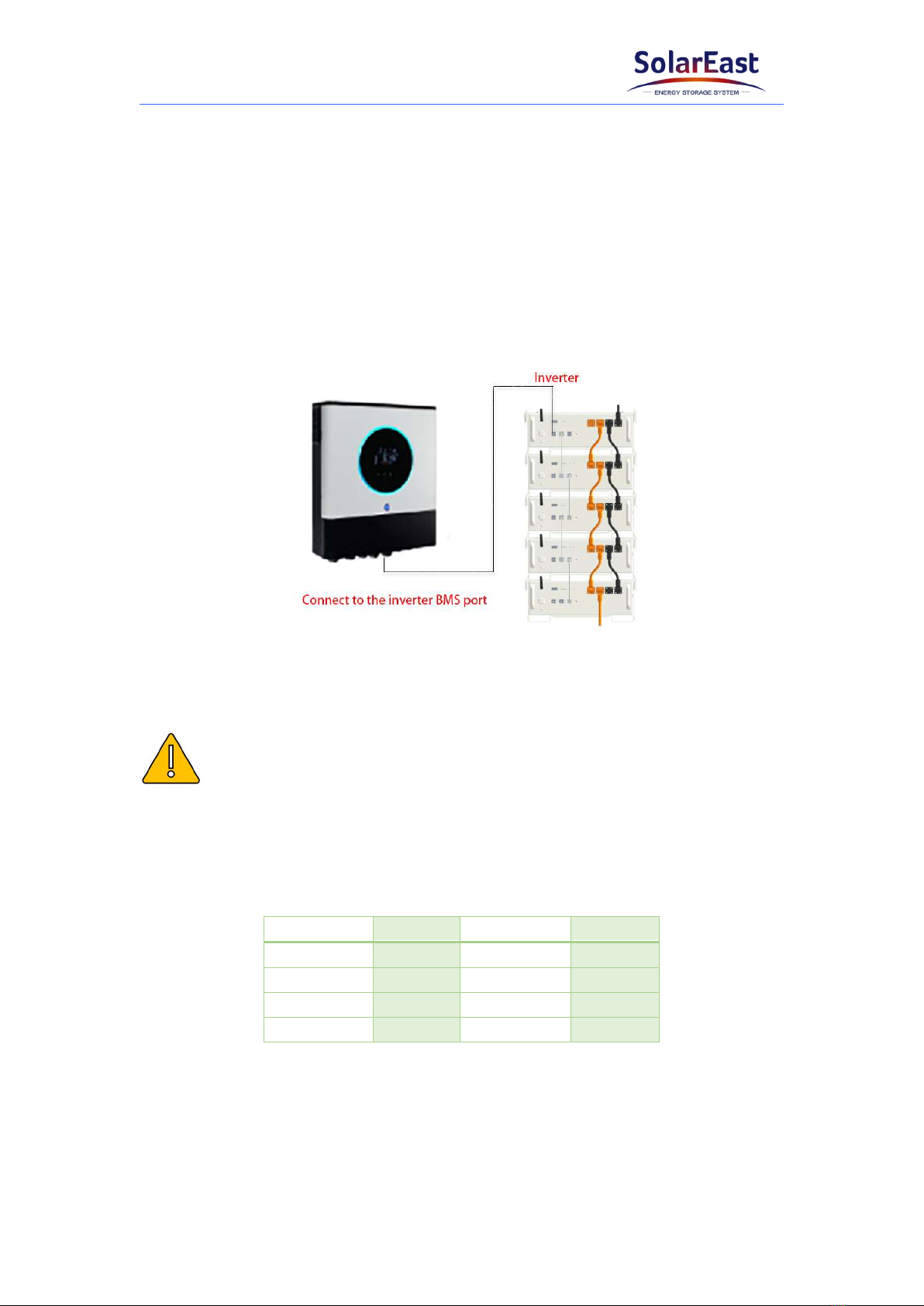
4.7 Connect to inverter
1) Connect the communication cable from the inverter port on the master battery to
the corresponding port of the inverter.
2) Select the communication mode by turning “ON” or “OFF” the DIP 5. The “OFF”
represents CAN while “ON” is RS485.
NOTICE
The Powercool-LFP5000 battery is designed to support both CAN and RS485
communication with the inverter. Please verify the communication mode of the inverter
and select the corresponding mode of the battery.
Definition of RJ45 Port Pin
PIN Number Definition PIN Number Definition
PIN1 - PIN5 CAN L
PIN2 - PIN6 GND
PIN3 - PIN7 485A
PIN4 CAN H PIN8 485B
3) Connect the power cables from BAT+ and BAT- on the master battery to the
corresponding ports of the inverter.
Table of contents
Other SolarEast Storage manuals

Popular Storage manuals by other brands


Thales
Thales Cinterion MV31-W Hardware interface description

Sony
Sony MSH-128 operating instructions

StorageTek
StorageTek 9710 System assurance guide

HP
HP Cray CS E1000 Disassembly instructions

Sony
Sony MicroVault USM-M1 Series operating instructions

Hama
Hama Highspeed FlashPen Floater USB 2.0 Operating instruction

Fujitsu
Fujitsu MAN3367FC - Enterprise 36.7 GB Hard Drive Product/maintenance manual

IBM
IBM DR550 Problem determination and service guide

Vertiv
Vertiv HPL Operation guide

Western Digital
Western Digital WD GREEN WD20NPVX specification

Storehouse
Storehouse 97563 Assembly, operating, and maintenance instructions

GE
GE AccessPoint 001890 User instructions