Solaris LoCor Recessed Electronic Dispenser User manual

8777002
Released February 22 2019
SOLARIS LOCOR® RECESSED ELECTRONIC ROLL TOWEL DISPENSER USER GUIDE (SKU NUMBERS D68011-A)
The LoCor Recessed Electronic Dispenser isdesigned to be mounted into the wall orinside arecessed cabinet onthe wall toyield maximum space in the
busy bathroom environment. The paper is delivered automatically by positioning a hand underneath the center bottom of the dispenser. The remaining
roll towel is maintained inside the unit to avoid cross contamination. With the stainless steel cover, the dispenser offers both attractive appearance and
easy cleaning ability; all together providing a maximum sanitation.
The dispenser is designed for an opening of 10 5/8” Width x 15 1/8” Length x 4” Depth.
TABLE OF CONTENT
I. Dispenser Installation Instruction ………………………………………………………………………………………………………….
1. Install Directly into the Wall – Using A Picture-Frame Panel …………………………………..……….……….
2. Install into Existing Recessed Cabinets on the Wall - Using Filler Panels ……………..……….……….….
Page 2
2a. Use Insert Filler Panel ………………………………………………………….……………….…………….
2b. Use Hanging Filler Panel ……………………….…………………………………………………………….
II. Changing Mounting Side of Cover …………………………………………………………………………………………………………..
III. Roll Support Installation …………………………………………………………………………………………………………………………
1. For 7” Width Solaris LoCor Paper Towel SKU Numbers 46897, 46989, 46899, 46902 ……………….
2. For 8” Width Solaris LoCor Paper Towel SKU Numbers 46896, 46901 ……………………………………..
IV. Power-up the Dispenser .....……………………………………………………………………………………………………………………
IX.Failure Diagnostics …………………………………………………………………………………………………………………………………
1
Outer dimension is 18.17" x 14.67" x 10.97", weighs approximately 9.8 lbs.
VI.Switch Control Settings ………………………………………………………………………………………………………………………....
VII.LED Indicator Light Function ………………………………………………………………………………………………………………...
VIII.Stub-Roll Transfer Loading ……………………………………………………………………………………………………………………..
V. Paper Loading andInitiate the First Dispense .......…………………………………………………………………………………
Page 2
Page 4
Page 5
Page 5
Page 7
Page 8
Page 8
Page 8
Page 9
Page 9
Page 10
Page 10
Page 10
Page 10

I. DISPENSER INSTALLATION INSTRUCTION
1. Install Directly into the Wall – Use A Picture-Frame Panel
Hardware provided with the dispenser:
oKey
o(4) Screws #10 x 1”L, Phillips Head
o(4) Wall Anchors
Tools and materials required (not provided):
-Stud Finder
-Pencil
-Tape Measure
-Level
-Knife or Saw (to cut drywall)
-Powered Screwdriver with Phillips Head and 1/4" Hex Head Drive
-Cotton Gloves
-(2) Studs 2” x 4” x 12”L
-(6) Screws #10 x 1 1/2”L, Phillips Head
Step 1: Dispenser Location
Determine the location of the dispenser to be mounted. Ensure there will be
no interference during the opening and closing of the cover or when paper is
dispensed at the bottom of the dispenser.
Step 2: Studs’ Location
Use a Stud Finder to find the location of the two studs on both sides of the
area where the dispenser will be mounted. Mark the locations of the studs.
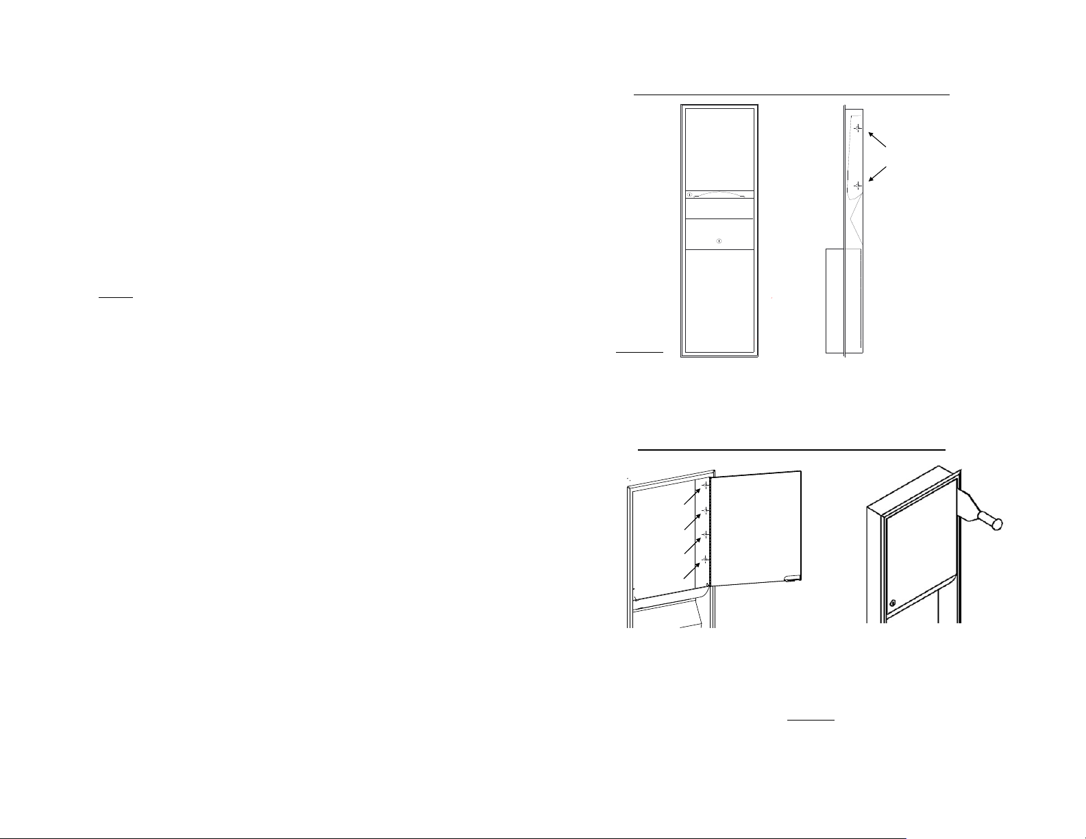
Step 3: Cut the Opening on Drywall
Knowing the studs’ location, the dispenser should be mounted roughly in the
middle, between the two studs. The bottom of the dispenser should be 48
inches from the floor.
To install the dispenser into the wall, it is required to cut an opening of
10 5/8” W x 15 1/8”L on the drywall.
Recommend to use a pencil outlining the opening before cutting into the
drywall:
-Using a tape measure, place a mark of 48” from the floor. Then use a
level to draw a horizontal line from the mark. This is the bottom line
of the opening.
-Using a tape measure, place a mark of 15 1/8” from the bottom line
drawn from the last step. Then use a level to draw a horizontal line
from the mark. This is the top line of the opening.
-Use the level to draw two vertical lines to connect the top and
bottom lines. These two lines should be 10 5/8” apart from each
other. These two lines should be roughly in the middle, between the
two studs.
Now use a knife or a saw to carefully cut the opening out of the drywall.
See Figure 1 for more details.
Floor
Figure 1.
10 5/8"
15 1/8"
48"
8777002
Released February 22 2019
2

Step 4: Install the Two Supporting Studs
Install thetwostuds(2” x 4” x 12”L) onthe left side and right side of
the opening, behind the drywall (Figure 2). Drive three screws #10 (1 1/2" L)
through the drywall into each stud on both sides (total of six screws to be
used).
Step 5:Install the Picture-Frame panel and the dispenser into the wall.
Remove the protecting film on the outside of the panel. Recommend touse
cotton gloves to handle the panel after the film is removed to avoid finger
prints.
Carefully place the dispenser into the big opening on the panel. Then install
the assembly (of the cover and the panel together) into the opening on the
wall. Slide the dispenser all the way in; ensure there is no gap between the
panel and the wall.
Use the key (provided) toopen the cover. Drivefour #10 screws (also
provided) into the mounting holes on the left and right sides ofthe dispenser
to secure the dispenser in position. See Figure 3 formore details.
The dispenser isnowready for Roll Support installation and paper loading.
Figure 2.
Figure 3.
PICTURE-FRAME
PANEL
screw# 10 in step 4
mounting holes
inside the
dispenser
supporting studs
8777002
Released February 22 2019
3
2. Install into Existing Recessed Cabinets on the Wall – Use Filler
Panels
Tools and materials required (not provided):
-Power Drill with:
oPhillips Head Drive
o1/4” Hex Head Drive
o1/8” Drill Bit
-Marker
-Cotton Gloves
-Other tools may be required, depends on the type of the existing
dispenser in the recessed cabinet
Step 1: Remove the Existing Dispenser from the Recessed Cabinet
Open the cover of the existing dispenser and remove the paper towel (if it is
present) to examine whether the dispenser was secured in the cabinet by
screws/nuts, rivets or by spot welding.
*If the existing dispenser is secured by screws, use the power drill with the
Phillips Head Drive to loosen the screws to remove the dispenser out of the
cabinet.
* If the existing dispenser is secured by nuts, use the appropriate socket to
loosen the nuts to remove the dispenser out of the unit.
* If the existing dispenser has the cover riveted or spot welded to the
recessed cabinet, use the power drill with the 1/8” drill-bit to drill out the
rivets and spot-welds inside of the dispenser. Then carefully use a hammer
and a chisel to separate the hinge side of the cover from the cabinet frame.
See Figure 5 for more details.
Here are some examples of the existing recessed dispensers:
Recessed Paper Towel Dispenser secured by screws/nuts
Recessed Paper Towel Dispenser secured by spot welds
Open the cover and
loosen screws/nuts on
the sides to remove
the existing dispenser
Use a hammer and a chisel to
separate the hinge side of the
cover from the cabinet frame.
Use power drill and 1/8” drill bit todrill out
the rivets or spot welds (from the inside of
the existing dispenser).
Figure 4.
Figure 5.
8777002
Released February 22 2019
4
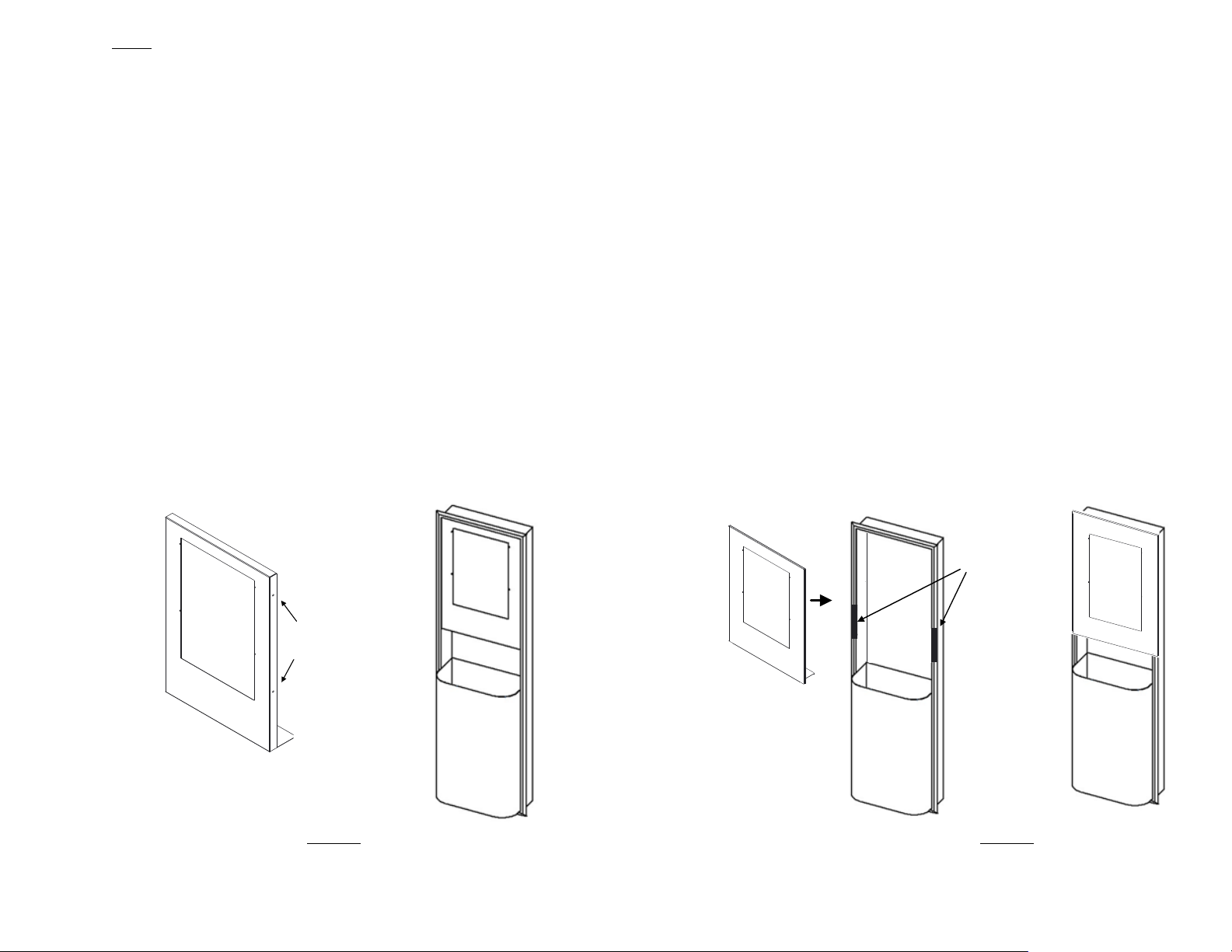
Step 2: Filler Panel Installation
a. Use Insert Filler Panel
Hardware provided with the Insert Filler Panel:
o(4) Screws #8 x 3/4”L, Hex Head
o(4) Screws #6 x 1 1/4”L, Phillips Head
Do not remove the protecting film on the outside of the panel yet.
-Place the panel (with theprotecting film still on) into the cabinet
with the top of the panel tobein the contact with the top of the
cabinet.
-Note that there are two mounting holes on each of the left and right
sidesof the panel.Use the marker to mark the holes’ locations.
Carefully remove the panel out of the cabinet.
-Use the power drill with the 1/8” drill-bit to drill four holes at the
marks. Each hole should be roughly 1-inch deep.
-Remove the protecting film on the outside of the panel. Recommend
to use cotton gloves to handle the panel after the film is removed to
avoid finger prints.
-Carefully slide the panel into the cabinet. Drive four #8x 3/4”L Hex
Head screws (provided) into the mounting holes on the left and right
sides of the panel to secure the panel tothe cabinet.
Figure 6.
b. Use Hanging Filler Panel
Hardware provided with the Hanging Filler Panel:
o(4) Screws #6 x 1 1/4”L, Phillips Head
o(3) Double Sided Tape Strips
Remove the protecting film on the outside of the panel. Recommend to put
the cotton glove on the one hand that is used to hold the panel to avoid
finger prints. The other hand that is used to peel the film will not need glove.
Use two double-sided tape strips (provided).
-Remove the backings on one side of the tape and place them with
the adhesive side onto the bezel as showed in Figure 7. Keep the
backings remaining on the front face of the tape.
-Loosen the screws that were used to secure the cabinet to the studs
(typically these screws locate on the left and right sides ofthe
cabinet). Store these screws for later use.Then pull the top part of
the cabinet out slightly, just enough to hook the top of the panel
onto the top of the cabinet.
-After the top of the panel ishung, remove the backings of the tape
and then press the panel onto the tape tosecure it in place.
-Install the mounting screws on the left and right sides the cabinet
to complete the panel installation.
Figure 7.
tape
mounting holes
double sided
Finished Look
Finished Look
8777002
Released February 22 2019
5
Step 3: Dispenser Installation
Hardware provided with the dispenser:
oKey
o(4) Screws #10 x 1”L, Phillips Head
o(4) Wall Anchors
Through the front opening of the panel, slide the dispenser all the way in,
make sure that the back of the dispenser is in contact evenly with the back of
the cabinet. There are two options to secure the dispenser:
Option 1: Drive the four screw# 10 (provided) into the mounting
holes on the back ofthe dispenser tosecure the dispenser tothe
cabinet.
Caution Note: The length of the screw# 10 is1 inch, which may be
longer than the thickness ofthe drywall on the back ofthe cabinet.
Ifitisnot acceptable, please use option 2.
Option 2:Drive the four screw# 8 (provided) into the front mounting
holes on the stainless steel panel tosecure the dispenser into place.
The dispenser is now ready for Roll Support installation and paper loading.
Figure 8.
8777002
Released February 22 2019
6
Note: If using the method described in option 2, it is recommended
to enlarge the front mounting holes of the panel (using an 1/8" drill
bit) prior to the installation. That will help drive the screws in the
metal easier.

The cover is designed to be mounted on either left or right side of the
housing. Manufacturing setting is left-side mounting. To change to right-side
mounting, follow steps 1 - 5:
Step 1:Remove Hinge Pins (Top & Bottom)
First remove the e-clips atthe end of the pins. Then remove the pins.
Step 2:Remove the Removable Hinges (Top & Bottom)
First remove the screws. Then remove the hinges.
Step 3: Remove the Door Seal Plug
Flex one of the legs to push the door plug out.
Step 4:Remove the Lock
First remove the screws. Then remove the lock.
Step 5:Reverse steps1 - 4 and switch side when install the components back
on the cover. Note that the Hinges and Pins should be installed on the same
side that the cover is desired to be mounted on. The Lock should be installed
on the opposite side of the Hinges. And the Plug should be installed on the
same side as the Hinges.
See Figure 9 for more details.
Pin
Removable Hinge
E-clip
Top Hinge
E-clip
Removable Hinge
Pin
Lock
Screws
Door Seal Plug
Flex one of
the three legs
to push the
plug out
II.CHANGING MOUNTING SIDE OF COVER
Figure 9.
Bottom Hinge
8777002
Released February 22 2019
7
The dispenser isdesigned to accept both the 7”and 8” wide LoCor Roll
Towels. Itisvery important toidentify the width of the paper roll before
installing the Roll Supports:
SKU Numbers for 7”Width LoCor Paper Towel:46897, 46898, 46899, 46902
SKU Numbers for 8”Width LoCor Paper Towel:46896, 46901
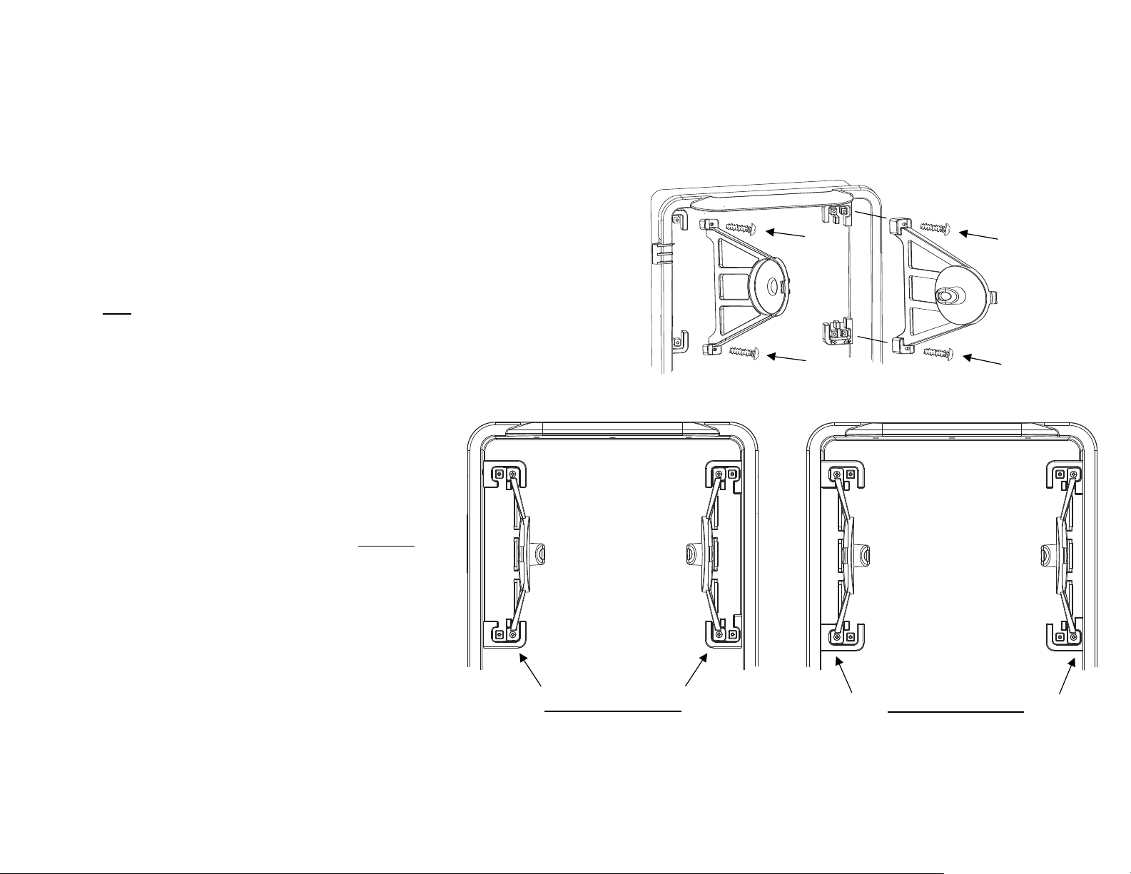
After identifying the paper roll width, install the Roll Supports from the
supplied kit included with the package:
- Two Roll Supports
- Four Screws
- Roll Support Installation Instruction Sheet
7" WIDTH ROLL SUPPORTS 8" WIDTH ROLL SUPPORTS
III.ROLL SUPPORTS INSTALLATION
Note: Need to use a Phillips Head Screwdriver for the installtion. Use four
screws (provided) to install the Roll Supports into the correct places on the
back of the housing. See Figure 10 for more details.
Figure 10.
8777002
Released February 22 2019
8

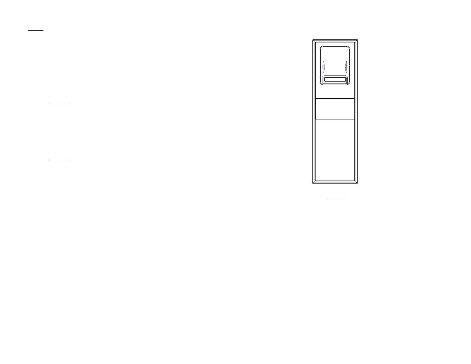
Figure 11. Top View Section-Cut of the Dispenser
STUB ROLL SUPPORTS
BATTERY
COVER
STUB-ROLL
MONITOR
TRANSFER
ARM
DC JACK
CONTROL
SWITCH
LED
LIGHT
Paper should be loaded with the paper “tail” unwinding from the back of
the roll. Place the paper "tail" under the Transfer Arm (Figure 11). Close
the cover and wait for the first LED flashing to indicate that the dispenser
is now ready for dispensing. Place a hand underneath the bottom center
of the dispenser to initiate the first dispense.
V.PAPER LOADING AND INITIATE THE FIRST DISPENSE
IV.POWER-UP THE DISPENSER
For use with LoCor paper towels only(SKU numbers 46896,
46897, 46898, 46899, 46901 and 46902). Other types ofpaper are
not acceptable.
Power-up the Dispenser Using Batteries
Recommend to use the four batteries provided with the
dispenser or use D-size alkaline batteries labeled with "LR20"
designation only.
Open the cover using the key supplied in the hardware pack.
Note that the battery compartment locating at the front of the
dispenser (Figure 11). Remove the Battery Cover by pushing on
the tab inward and lifting up. Install four batteries into the
battery-compartment with the orientation as showed on the
bottom of the compartment. Close the Battery Cover.
Power-up the Dispenser Using a Power Converter Plug
Recommend to use the power converter plug provided with the
dispenser only.
First, verify the dispenser does not have batteries installed.
Remove the dispenser from the mounting cabinet/wall if the
dispenser was mounted. Note the location of the DC Jack in in
the back of the dispenser (Figure 11). Make sure there is an
access hole and enough space to safely route the wire into the
cabinet or into the wall. Plug the power converter into the DC
Jack. Install the dispenser. Plug the converter into the outlet.
For warranty and safety purposes, it is required the power
converter must be plugged in an AC outlet that is not accessible
to the users. If not available, consult a licensed electrical
contractor. The power converter output is to be routed through
the mounting wall as a low voltage, energy limited circuit, similar
to a thermostat wire, with no requirement for electrical box or
attachment strain relief.
8777002
Released February 22 2019
9

For further assistance, please contact technical dispenser support at (920) 940-8904
VI.SWITCH CONTROL SETTINGS
There are three switches available to customize the control system. These
switches are inside, to the back-right corner of the dispenser (see Figure 11).
Switch# 1 is designed for paper saving method. Using this method, any dispense
that occurs within 3 seconds of the previous dispense will result in a sheet that is
shorter (paper saving) than the initial dispense.
Switch# 2 is designed to control the delay-time between two dispense actuations.
Switch# 3 is designed to control the sheet length of each regular dispense.
Switch# 1: Paper Saving Mode
Switch# 2: Dispensing Delay
Switch# 3: Paper Length
12.5% Saving
0% Saving
25% Saving
Approximately 2 seconds
Approximately 1 seconds
Approximately 1/2 seconds
Long
Medium
Short
VII.LED INDICATOR LIGHT FUNCTION
The LED indicator light located at the right top corner of the opening where the
paper is dispensed.
If using batteries, the LED light will flash one time after the batteries are installed
correctly to indicate that the unit is powered up. The LED light will also flash
once after every dispense to indicate the unit is ready for the next use. When the
batteries need replacement, the LED light will flash every 1.5 seconds.
1. If the LED is flashing, batteries may need to be replaced (if using batteries).
2. If the LED is not flashing, make sure batteries are present and loaded in
the correct orientation. If using Power Converter Plug, check the plug-
connections.
3. Open the cover:
a. Make sure paper is loaded correctly, on the correct roll holders.
b. Make sure paper is not jammed, paper roll turns freely and the
paper path is clear of obstructions.
8777002
Released February 22 2019
10
If using Power Converter Plug, the LED light will flash every 1.5 seconds to indicate
that the plug is connected to the power supply.
VIII.STUB-ROLL TRANSFER LOADING
When the paper roll gets down to 3-inch in diameter or smaller, the roll can be
transfered to the stub-roll holders in the lower, rear section of the dispenser.
Place the paper "tail" underneath the Stub-Roll Monitor so that paper from the
stub-roll can be used up first.
Install a new full roll of paper in the upper roll holders. Place the new paper
"tail" on top of the Stub-Roll Monitor and under the Transfer Arm as showed
in the "Stub-Roll Transfering" instruction graphic inside the cover. Paper from
the new roll will automatically engage and feed out of the dispenser when the
stub-roll paper runs out.
IX.FAILURE DIAGNOSTICS
If the unit is not dispense:
Note: When the Paper Saving Mode is activated (switch# 1 is positioning at
12.5% or 25% saving), the system will overide the time-delay setting, which
means the delay time will always be 1/2 seconds between every dispense.
This manual suits for next models
1
Table of contents
Other Solaris Dispenser manuals


