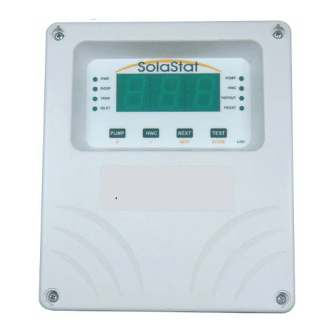
SolaStat AlphaStat-Plus User manual

AlphaStat-Plus
Installation Guide.
ISO9001
E
G
I
S
T
E
R
R
E
D
S
U
P
P
I
R
E
L
Z985
TECHNOLOGY
& QUALITY
A
W
A
R
D
19.08-1

AlphaStat-Plus Installation Guide Index.
Description, Ordering and Specifications.
Index page 2
Features page 3
Introduction page 3
Ordering Information. page 3
AlphaStat-Plus Users Guide.
Principle of Operation. page 4
Demand Mode page 4
Bio-Safe Mode page 4
Away Mode page 4
Sensor Diagnostics. page 4
Smart Shutdown: page 4
Test. page 4
Display Panel Description. page 5
Optional System Enhancements. page 5
AlphaStat-Plus SystemAdjustable Values. page 6
Installer Details. page 6
AlphaStat-Plus Safety Instructions.
General Safety Instructions. page 7
Installation Precautions. page 7
Electrical Precautions. page 7
Permanent Wiring. page 7
AlphaStat Plus Mounting.
Where to mount the AlphaStat-Plus. page 8
Mounting the AlphaStat-Plus. page 8
Mounting the Sensor. page 8
AlphaStat-Plus Operation.
Connect the HWC Electric Element. page 9
Basic AlphaStat-Plus-1 Installation. page 9
Power Up. page 10
AlphaStat-Plus Programming.
AlphaStat-Plus Programming. page 11
AlphaStat-Plus Pump ON / Pump OFF Adjustable Range. page 11
Notes on AlphaStat-Plus Programming. page 11
Explanation of the Bio-Safe Mode. page 12
AlphaStat-Plus Sensor Maintenance.
Lengthening AlphaStat-Plus Sensor Wire. page 13
Replacing a AlphaStat-Plus Sensor. page 13
AlphaStat-Plus Sensor Resistance Table page 13
AlphaStat-Plus Specifications and Product Liability. page 14
AlphaStat-Plus Trouble-shooting Guide. page 15
AlphaStat-Plus Plumbing Issues.
Disclaimer. page 16
Introduction. page 16
Solar Hot Water Specifics. page 16
Tempering valve. page 16
Pressure relief valves. page 16
19.08-2

AlphaStat-Plus.
HWC Element Controller.
Features.
Automatic HWC Electric Element Control.
Saves Power; Saves Money.
Large 20mm Soft Green Digital LED Display c/w 8 Status Lights.
User Adjustable Water Temperature Settings.
Biosafe Function for Legionella Protection.
High Quality, Efficiency, Reliability and +/-1C Accuracy.
Stainless Steel, Water Resistant Temperature Sensor.
Pre-Programmed to Customer’s Specification at No Extra Cost.
Sensor Diagnostics and Smart Shutdown.
Easy to Install with External Mounting Holes.
Complies with Safety & EMC standards.
Enclosure and cables UV resistant.
Water Resistant and Rear Cable Entry Options.
16Amp Relay Std with Permanent Wiring.
Introduction.
TheAlphaStat-Plus is an advanced HWC electric element controller thatautomaticallysaveselectricity
while maintaining a sufficient and safe supply of hot water. It also constantly keeps track of the hot water
temperature over a 72 hour period and switches the HWC electric element on and off at exactly the right
time.
TheAlphaStat-Plus enhances the hot water system byan easytoread temperaturedisplay and settings,
with the options of extra hot water at a one off key press, and an ‘AWAY’ key for holiday mode to ensure
that no electricity is used.
The AlphaStat-Plus is easy to install, easy to use, easy to programme and visually appealing.
Senztek NZ Ltd has experienceindesigning andmanufacturingHot Water ControllerstoIndustrial Electronic
Standards for over 15 years. This has earned SolaStat a reputation for Quality, Accuracy, Efficiency and
Reliability.
Ordering Information.
AlphaStat-Plus-1 Standard; 1 x 16A Relay, Digital Display, 8 Status Lights, 10m Tank Sensor,
2m Mains Cable and Outlet.
AlphaStat-Plus- - - - Adjustable Value Specify adjustable values as required.
Rly PT PS
Quality Assurance Programme.
ThemoderntechnologyandstrictproceduresoftheISO9001QualityAssuranceProgrammeappliedduring
design, development, production and final inspection grant the long term reliability of the instrument.
Z985
ISO9001
E
G
I
S
T
E
R
R
E
D
S
U
P
P
I
R
E
L
TECHNOLOGY
& QUALITY
A
W
A
R
D
19.08-3
High temperature silicon sensor cable, water resistant enclosure, and rear cable entry options are available.
.snoitpOgnignaRsulP-tatSahplA
yaleR snoitpO ylR rewoP lppuS
y
SP elbatsujdA eulaV yficepS nihtiW .dtS ledoM elbatsujdA eulaV yficepS nihtiW .dtS ledoM
A61x11 cd/caV462~58H
ffOteSC57~12C05 dnameDC001~02C06
cdV09~22 M nOteS C47~02 C53 efaSoiB FFO/C07~05 C06
cd/caV82~01L
AlphaStat Models Include:
AlphaStat-Plus: Controller c/w Display.
SolaStat-Rly: Slave Relay for HWC Control.
SolaData: PC Datalogging & Comms.
Note: When used with the mains cable supplied the total current must not exceed 10Amaximum.

AlphaStat-Plus Users Guide.
Your AlphaStat-Plus has a microcomputer at its core that intelligently and automatically controls your hot
water system at greater efficiency. TheAlphaStat-Plus measures the cylinder water temperature and turns
on the element at the optimum time.
TheAlphaStat-Plus allowsintelligentcontrol of theelectricelementused inthehotwater tank.TheAlphaStat-
Plus can prevent the electric element coming on while you are on holiday (‘Away’ mode), maintain an
efficient temperature in your hot water cylinder using two user-configurable reference points (Reheat) and
ensure that safe water conditions are maintained (BioSafe) and a one off heat up (Demand). These controls
will save a considerable amount of electricity.
TheAlphaStat-Plus has advanced features that protect the system from damage, run self diagnostics, self
correct some problems and will keep you informed as to what the AlphaStat-Plus is measuring and what
decisions it is making.
Principle of operation.
The hot water tank sensor is called: ‘TANK’
The upper temperature threshold is called: ‘SET OFF’
The lower temperature threshold is called: ‘SET ON’
The AlphaStat-Plus is a HWC electric element controller. The controller measures the temperature at the
‘TANK’ sensor and compares this to the ‘SET ON’ threshold. If the tank is below this threshold, then the
element is turned on and heats the water in the cylinder. Once the tank has reached the ‘SET OFF’
threshold, the element is turned off to save power.
The AlphaStat-Plus has other special features to those mentioned above.
The Demand mode is where the user can initiate an immediate reheat of the cylinder for times when
there will shortly be a heavy draw off of. This will heat the cylinder to a factory- or installer- defined
‘Demand’value (60C standard)whichwill normally be higherthantheregular‘SET OFF’targettemperature.
The BioSafe mode is to prevent the growth of dangerous organisms within the hot water cylinder.
The cylinder must reach a preset temperature (60C standard) at least once every 72 hours. If this does not
happen, the element is turned on and held on until a safe temperature is reached.
The ‘AWAY’ function is to allow for long periods where electric boosting of the hot water is not
required. Pressing the ‘AWAY’ button prevents the cylinder from turning the element on. This takes
precedence over all other functions . To leave ‘AWAY’ mode, simply press the ‘AWAY’ button again.
NOTE:SenztekNZ Ltdrecommendsthat when the‘AWAY’buttonhasbeen turned onandthenoffsometime
later, no hot water be drawn off until the Biosafe light goes off. This is to ensure that the water has been
heated up to safe level.
Sensor diagnostics: The AlphaStat-Plus constantly checks the sensor. If the sensor is below -20C
the display reads ‘Lo’. If the sensor is above 140C the display reads ‘Hi’. If the sensor is outside the
specified temperature range of -40C to 150C then the Display reads ‘SSd’ and the controller enters Smart
Shutdown mode. When the display reads ‘SSd’the sensor has either a steady light for a temperature above
150C (possibly shorted sensor or wire) or a flashing light for a temperature below -40C (possibly open
sensor or broken wire). For example if the sensor wire is cut during some building work then theAlphaStat-
Plus display reads ‘SSd’, the ‘Tank’ light flashes and the controller enters Smart Shutdown mode until the
wire is repaired.
Smart Shutdown (SSd): In Smart Shutdown mode, the Display reads ‘SSd’ and the element is held
ontoensure hotwater. TheHotWaterTankTemperaturewillbe controlled bytheHot WaterTankThermostat
for the electric element.
Test: Briefly pressing this button will cause all the lights to flash on for 3 seconds then display for 3
seconds the number of times the element has been on. This count will reset and start again after ‘999’.
19.08-4

The ‘PWR’ light on indicates that power is being applied to the unit.
‘TANK’, ‘SET OFF’ and ‘SET ON’ lights will be on to indicate which temperature is being displayed.
Only 1 of the 3 can ever be on.
The ‘HWC’ light will be on when the HWC element is on.
The ‘REHEAT’ light on indicates that the cylinder has dropped below the ‘SET ON’ point and the
element has turned on. The controller will remain in this mode until the ‘SET OFF’ point is reached.
The ‘BIOSAFE’ light comes on, along with the HWC element, when 72 hours have passed without the
cylinder reaching a safe temperature. The light and element will turn off once a safe temperature has been
reached.
The ‘AWAY’ light flashes to indicate that the user has placed the controller in a suspended state. No
power will be applied to the HWC until the ‘AWAY’ button is pressed again to cancel it. The AlphaStat will
remember the ‘AWAY’ mode even if the power goes off and comes on again.
The ‘HWC’ button puts the controller into ‘Demand’ mode, initiating a manual reheat of the hot water
cylinder to a preset demand temperature. Only the HWC light will come on in this mode. To cancel
‘Demand mode early, press the HWC button again.
The ‘AWAY’ button puts the controller into ‘AWAY’ mode; to cancel press the ‘AWAY’ button again.
The ‘NEXT’ button will step from Tank to Set Off to Set On and the display will show the relevant
temperature in C. If the Tank sensor is below -20C the display reads ‘Lo’. If the Tank sensor is above 140C
the display reads ‘Hi’. If the sensor is outside the specified temperature range of -40C to 150C then the
Display will read ‘SSd’ and the ‘NEXT’ button is disabled.
‘SET OFF’ and ‘SET ON’ temperatures may be changed while they are displayed, by pressing the
buttons marked with ‘+’and ‘-’ in yellow (‘HWC’and ‘AWAY’). The limits are 20C and 75C, but note that the
‘SET OFF’temperature will always be higher than the ‘SET ON’temperature. If sixty seconds pass and no
buttons have been pressed, the display reverts to ‘TANK’.
The ‘TEST’button will check the system (all lights flash) then display the number of times the element
has been on. This count will reset and start again after ‘999’.
Optional System Enhancements.
SolaStat-Rly An external Slave Relay Module for HWC control.
SolaData A data comms option that will send what the AlphaStat-Plus is doing to your PC and
visually present the information with graphs, logic states and status information.
AlphaStat-Plus Display Panel Description.
19.08-5

AlphaStat-Plus System Adjustable Values.
Installer to fill in at installation time or after any change in program Adjustable Values.
Notes.
1. Set Off must always be higher than Set On.
2. Demand should generally be higher than Set Off.
3. Biosafe disabled is indicated by ‘OFF‘
seulaVelbatsujdAmetsyS
noitcnuF 1-sulP-tatSahplA seulaVyrotcaF noitallatsnI seulaV
ffOteS
C05C____
nOteS
C53C____
dnameD
C06C____
efasoiB
C06C____
Installer Details.
Contact: ................................................................................................
Phone: ................................................................................................
Address: ................................................................................................
................................................................................................
................................................................................................
19.08-6

AlphaStat-Plus Safety Instructions and Limit of Liability.
Read safety instructions and limit of liability before proceeding with the installation.
General Safety Instructions.
1. This installation guide is for the installation ofAlphaStat-Plus hot water controllers only and is not an
installation guide for any other part.
2. The complete installation should be checked at least annually for damage or malfunction.
3. All servicing to be carried out by an authorised service agent only.
4. All aspects of the installation must comply with local electrical and plumbing regulations (and any
special hot water regulations).
5. The installation must have a Tempering Valve Installed as temperatures higher than 60C can be set.
6. Adjustable values must not be set higher than 70C for Glass Lined Hot Water Cylinders.
Installation Precautions.
1. Must be installed away from water sources such as rain, leaking pipes, or wet floors and must not be
installed in damp areas like bathrooms.
2. Must be installed away from direct sunlight, flammable liquids or radiant heat sources.
3. Power leads must be facing directly down, not sideways or upwards.
4. Must be in a safe environment for users to inspect display panel.
5. Failure to mount sensor correctly can lead to a poorly controlled hot water system with safety
issues like overheating and over pressure damage to the plumbing and hot water tank.
6. Alteration of installer level program values outside those recommended values by SolaStat and other
parts suppliers (especially hot water tank manufacturer’s maximum recommended temperature) can
lead to dangerous conditions and/ or damage to parts of the hot water system.
Electrical Precautions.
1. All mains voltage electrical work to be carried out by a qualified electrician, especially external power
outlet socket installation.
2. It is recommended that sensor leads be kept 300mm away from mains and comms cables.
3. Do not use mains power extension cords unless approved by the manufacturer. Water resistant plugs
and sockets should be used.
4. TheAlphaStat-Plus controlled output (HWC) is connected to the input power supply wiring and is not
isolated from it. Supply voltages will be output through that outlet during activation. (The HWC outlet
is labelled ‘PUMP OUT’’ on the printed circuit board.)
5. Always usewithinspecifiedvoltageandload ranges. Never usewithdamaged leads, plugsorsockets.
6. Do not allow the sensor cable to come within 10mm of the high voltage connectors or components
inside the enclosure.
7. The HWC output is normally used in conjunction with a SolaStat-Rly. This is due to the high power
levels used by hot water electric elements, and completely isolates the AlphaStat-Plus from the
HWC circuit.
This will also ensure any remote hot water electric element control (eg Ripple Control) will
not remove power to the AlphaStat. When used with the mains cable supplied the total current must not
exceed 10A maximum.
Notes on Permanent Wiring.
Permanent wiring of the AlphaStat-Plus directly to the HWC electric element is possible (no SolaStat-Rly).
However Electricity Suppliers may remotely turn off the HWC element using controlled wiring. Do not
power the AlphaStat-Plus from the controlled wiring and do not bypass the controlled wiring. The
recommended method is to use the SolaStat-Rly. This is a high power relay and connects between the
controlled wiring and the HWC element. NO liability will be accepted by Senztek NZ Ltd or any of it’s
authorisedagents for permanentwiringinstallations.For permanent wiringthemaximumload of theelement
must be less than 16Amps @ 25C (Typ 3kW Max Element).
CAUTION: Dangerous Voltages may be present. The AlphaStat has no user serviceable parts.
Protective enclosure only to be opened by qualified personnel.
Remove ALL power sources before removing protective cover.
19.08-7

AlphaStat-Plus Mounting.
Where to mount the AlphaStat-Plus.
1. Against a flat vertical surface with sufficient strength to hold the enclosure and any additional
weight from the plugs, sockets and cables.
2. Power leads must be facing directly down, not sideways or up.
3. Safe for users to inspect.
4. The display can be easily read and buttons accessed.
5. Allow for cable runs, location of power outlets and lengths of wires.
6. Allow space for SolaStat-Rly if used to control the hot water tank electric element.
Mounting the AlphaStat-Plus.
1. There is no need to open the enclosure during a standard installation.
2. Allow for the enclosure dropping 5mm from screw centres once mounted (keyhole mounting
system).
3. Place drill guide template against wall, checking for level alignment. 4 screws are supplied, 2
are chip board screws and 2 are combination Gib/ wood screws. It is recommended that all
4 mounting holes are used with at least 2 firmly secured into wood. The outer plastic Gib
anchors will self tap into Gib board and their inner metal screws fix into the centre of the
plastic anchors.
4. Mark and drill/ screw as appropriate leaving the heads of the screws above the surface by
approximately 3mm.
5. Place unit over the 4 screw heads, unit should slide down 5mm into the ‘key’ slots and
become secured to the wall. You will need to adjust screw height to obtain a secure fit.
Mounting the Sensor.
This is Critical to the Success of the Installation.
The sensor is the only way the AlphaStat-Plus can efficiently control and protect the system.
The ‘TANK’ Sensor should always be installed above the HWC electric element for the controller
to work efficiently.
The‘TANK’sensor isbestfitted intoametalimmersion ‘pocket’ intheupperregion of the HWC. The
position of the Tank sensor will vary the amount of water in the HWC that will be controlled at the
required temperature. As an example for a 300l vertical tank mounting the sensor 1/3 of the way
down from the top of the HWC will give about 100l of water that is heated within the control
parameters. This increases efficiency as only the amount of water required in normal household
use is controlled rather than all the water in the HWC. The sensor must be mounted above the
electric element. Liberally apply heat transfer compound between the sensor and the lining of the
‘pocket’. If a ‘pocket’ is not available then bond the sensor against the metal wall of the tank (not
the outside cladding or insulation) using thermal transfer compound between the tank and sensor.
Warning.
1. Removing or cutting the cladding may void hot water tank warranty.
2. Sensor must not be immersed in water.
3. It is recommended that sensor leads be kept 300mm away from mains and comms cables.
4. Failure to properly mount the ‘Tank’ sensor as prescribed above can result in;
a. The system may not operate at greatest efficiency.
b. Theremaybeinaccurate‘BioSafe’sensing.FordangersrefertoBioSafeAdjustmentValue.
c. Hot water readings on the display may be misleading.
d. HWC Control may not work and HWC light may never operate or operate continually.
19.08-8
Warning:
These products are not designed for use in, and should not be used for patient connected applications. In
any critical installation an independent fail-safe back-up system must always be implemented.

AlphaStat-Plus Operation.
Basic AlphaStat-Plus-1 Installation.
TheAlphaStat-Plus-1controllingtheHWC element via the SolaStat-Rly Relay Module. Plug in the SolaStat-
Rly to the ‘HWC’ socket on the AlphaStat-Plus. Set the HWC Thermostat to the Maximum Temperature.
19.08-9
Note. These diagrams are only to be used as a general guide and not all the required components are
shown.Eachinstallationneedstobe customised to suititssituation.Alwaysusebest plumbing andelectrical
practices, and comply to any regulatory requirements.
AlphaStat-Plus-1 Fixed Wiring Installation.
Set the HWC Thermostat to the Maximum Temperature.
.
TANK SENSOR
HOT WATER OUT
DIFFERENTIAL CONTROLLER
TEMPERATURE/PRESSURE
TEMPERING
VALVE
KEY: = WATER FLOW.
RELEASE VALVE
COLD WATER INLET
COLD WATER IN
HEATING
HWC
ELEMENT
ELECTRIC
SOLASTAT-RLY
ALPHASTAT-PLUS
THERMOSTAT
TURNED TO MAX
SWITCH
NEUT
EARTH Phase (Brown)
to HWC Switch
Phase (Brown)
to Element
WIRES TO HWC
MUST BE HIGH
TEMPERATURE TYPE
PRE-WIRED
PLUG &
LEAD
30A MAX
240Vac
.
COLD WATER IN
ELEMENT E
N
P
.
THERMOSTAT
TURNED TO MAX
SENSOR WIRES
ARE NOT POLARITY
SENSITIVE
WIRES TO HWC
MUST BE HIGH
TEMPERATURE TYPE
PHASE = BROWN OR RED
NEUTRAL = BLUE OR BLACK
EARTH = GREEN/YELLOW OR GREEN
TEMPERATURE/PRESSURE
RELEASE VALVE
TANK SENSOR
ELECTRIC
HEATING
PHASE
NEUTRAL
EARTH
PHASE
NEUTRAL
EARTH
SENSOR
HOT WATER OUT
TEMPERING
VALVE
COLD WATER IN
HWC Supply
16A MAX
240Vac

AlphaStat-Plus Power Up.
Before you connect the power;
1. Read safety instructions, warnings and limit of liability before proceeding.
2. Complete all the installation and securely mount theAlphaStat-Plus.
3. Power outlet socket to be installed by a qualified electrician.
4. SolaStat-Rly to be installed by qualified person.
5. Ensure suitable over-current protection and RCD Protection for the AlphaStat-Plus is in place.
6. There is no water, metal shavings or other electrical hazards to contaminate the plug, socket and
surrounding environment.
7. The mechanical Hot Water Thermostat for the Electric Element MUST be installed in series with the
element and MUST be set higher than the temperature of all the adjustable values for the HWC
Control Modes to operate correctly. The Hot Water Thermostat for the Electric Element is only used
as a fail safe feature and in normal operation will never operate. We recommend setting the Hot
Water Thermostat to the Maximum Temperature. Refer to the Trouble Shooting Guide for errors that
an be caused by incorrect Hot Water Thermostat settings.
Only then;
Plug it in and turn it on.
What You Should See.
The first thing you should see after power up is;
1. A digital readout of the ‘TANK’ temperature in degrees Celsius.
2. On the left the ‘PWR’ light and the ‘TANK’ light shouuld be on.
3. On the right the lights will be on depending on how the hot water system is operating.
The AlphaStat-Plus is now installed and should be working. It would be best to observe some hot water
heating cycles but this will depend on the temperatures in the system. Check all functions are working
correctly before leaving the installation.
Note 1. See User Guide for explanation of display and status lights.
Note 2. See “Trouble shooting” section if the system is not working correctly.
Note on BioSafe After Power-up.
When the AlphaStat-Plus is turned on either for the first time or after a power failure the BioSafe 72 hour
timer starts from power up (unless the temperature in the tank is greater than the BioSafe Temperature).All
timers are approximate only.
19.08-10

AlphaStat-Plus Programming
If the Adjustable Values from the factory are inappropriate for the installation (see included document
stating programmed values) then the unit needs to be programmed.
The programming access code is for distributor or installer use only, as using incorrect Adjustable Values
can cause inefficiencies in the system or cause damage to the system voiding the warranty.
Once new values are ‘stored’they are permanently written into memory and will be retained when power is
removed.
Note: Immediately after reprogramming please fill out the ‘Installation Adjustable Values’ in the ‘System
Adjustable Values’ table in the user guide. (Page 6.)
These instructions refer to the small yellow letters/words under the buttons on the AlphaStat-Plus.
1. Enter the installer programming access code. Available from distributors.
2. Every 10 seconds the characters ‘PRG’ will flash on the display indicating programming mode.
3. The ‘HWC’ light will be on to indicate the number being displayed is the ‘Demand’ value.
4. The ‘Demand’ can be adjusted using the ‘+’ and ‘-‘.
* Press ‘NEXT’ to move on to the next value.
5. Now the ‘BioSafe’ light will be on to indicate the number being displayed is the ‘BioSafe’ value.
6. The ‘BioSafe’ can be adjusted using the ‘+’ and ‘-‘.
7. All the values are now entered. The values can be checked by simply pressing ‘NEXT’ to cycle
through all the values noting which light is on and what value is displayed (as per AlphaStat-Plus
Programming Table).
8. To store all the values in permanent memory press ‘STORE’ at any stage. The values will be written
to memory and the unit will exit programming mode and return to automatic operation. The unit will
also store the values and exit if no key is pressed for a minute while in the programming mode.
9. Fill out the ‘System Adjustable Values’ in the user guide. (Page 6.)
AlphaStat-Plus Programming Table for Adjustable Values.
19.08-11
Notes on AlphaStat-Plus Programming. Also refer principle of operation.
1. SET OFF must always be higher than SET ON.
2. Demand should generally be higher than SET OFF.
3. A disabled value is indicated by ‘OFF‘
4. Fill out programming record in User Guide.
seulaVelbatsujdArofelbaTgnimmargorP
seulaVelbatsujdA noitacidnithgiL lacipyT egnaR noitcnuF/elbasiD
dnameDydaetsCWHC06C001-02a/n
efasoiB ydaetsefasoiB C06 C07-05 .'FFO'=yalpsiD.elbasiD=C05<

Explanation of BioSafe mode
This is a safeguard against tepid water creating a health hazard*.
The AlphaStat-Plus monitors the water temperature at the upper part of the hot water tank. BioSafe must
always be enabled for Potable water installations.
If the water does not reach a preset temperature called ‘BioSafe’(Adjustable from 50~70C) every 72 hours
all other functions (exceptAway) are overridden, the HWC light will flash fast and the electric element turns
ON and heats the water to a safe level. 72 hour timer is approximate only. Biosafe is OFF below 50C.
BioSafe Disclaimer
Senztek NZ Ltd makes the following observations about the BioSafe mode and bacteria in tepid water
based on published scientific articles and laws passed in some countries. Senztek NZ Ltd in no way claims
this information is a guarantee for safe practices or that the recommendations will prevent any or all forms
of tepid water infection. Neither do these recommendations extend to other parts of the plumbing other than
the hot water tank.
* Dangerous organisms can multiply in tepid water (especially 30 to 45ºC) and when aerosoled (e.g. in a
shower) can cause pneumonia type symptoms.
If the water is raised to 50ºC all growth stops, when the water is above 55ºC the organisms start dying and
at 60ºC they die very quickly. Other factors will influence the level of growth or decimation. Copper pipes
and tanks help kill these organisms, as will stainless steel (to a lesser extent) and water flow will keep the
numbers down but sludge and rust deposits will enhance growth.
It is therefore prudent to ensure that any domestic hot water system storage tank is hotter than 60ºC top to
bottom at least once a day. To achieve this may require a tank destratification pump or other similar mecha-
nism as only the Tank sensor is monitoring the cylinder temperature. This is in line with regulations in some
countriesandthe strong recommendation of Senztek NZ Ltd.The BioSafe function ensures the tanksensor
reaches the BioSafe Value (SolaStat recommends 60C) once a day . This BioSafe temperature is ad-
justable only to allow for sensor interface errors or an even hotter target temperature for greater caution.
19.08-12

19.08-13
AlphaStat-Plus Sensor Maintenance.
Lengthening AlphaStat-Plus Sensor Wire.
The sensor wire can be lengthened within certain guidelines. Poor connections or induced interference can
cause false temperature readings.
1. The sensor is not polarized- it can be connected either way around.
2. The wire normally used for sensor lengthening is twin 0.5mm^2 stranded speaker wire.
3. Firmly attach wires to each other by either soldering (heatshrink over each joint) or by quality screw
terminals. Joins must be kept dry.
4. It is recommended that sensor leads be kept 300mm away from mains and comms cables.
5. Over 20 metres; extra care must be taken to avoid electrical interference being picked up.
6. In ‘noisier’ electrical environments screened cable may be required.
7. The absolute maximum cable length is 100 metres.
Replacing an AlphaStat-Plus Sensor.
If a damaged sensor needs to be replaced then the cover of the enclosure will need to be opened unless
the choice is made to join the wires externally (see “Sensor Wire Lengthening” section).
1. Remove the mains power supply, preferably remove the plug from the wall socket. Make sure no
other power source is feeding back through other connections.
2. Remove the 4 screw covers on each corner of the lid of the enclosure. This will require a fine tipped
tool such as a screw driver. Be careful not to damage the lid. Always press the tool away from you to
avoid injury if you slip.
3. Remove the 4 screws that hold the lid on.
4. Unscrew the damaged sensor from the terminal block.
5. Loosen the cable clamp for the sensor leads.
6. Carefully pull the wire back through the opening in the bottom case.
7. Thread the new sensor wire back through where the old one came from.
8. Place the wires of the new sensor into the terminal block where the old sensor came from and
retighten the screws.
9. Do not allow the sensor cable to come within 10mm of the high voltage connectors or components
inside the enclosure. Tighten the screws on the cable clamp.
10. Replace the lid, replace the 4 screws and tighten.
11. Push in 4 new screw covers available from your distributor or Senztek NZ Ltd. Note: there are
locating lugs to ensure correct orientation.
12. Reconnect the AlphaStat-Plus and turn on the power.
13. Check sensor is reading correctly and checkAlphaStat-Plus operation as per “WhatYou Should See”
section of this manual.
The table below has the correct resistance values of the sensor at different temperatures. The sensor must
be removed from the AlphaStat-Plus to measure these values correctly. Follow the above procedure for
removal of the sensor.
CAUTION: Dangerous Voltages may be present. The AlphaStat has no user serviceable parts.
Protective enclosure only to be opened by qualified personnel.
Remove ALL power sources before removing protective cover.
secnatsiseRrosneS erutarepmeT kniecnatsiseR ::
:
::
Cº052.72
Cº52 00.01
Cº05261.4
Cº57 529.1
Cº001379.0
.'trohs'roC051evobA yalpsiDno'dSS' nOthgiLrosneS 003.0<
.'nepo'roC04-woleB yalpsiDno'dSS' gnihsalFthgiLrosneS 002>
A ‘short’ circuit can be caused by the sensor wires being
connected together. Check the wires are not partially cut.
and that moisture is not getting into the sensor causing cor-
rosion.
An ‘open’ circuit can be caused by the sensor wires being
broken. Check the wires are not broken and that moisture is
not getting into the sensor causing corrosion.

19.08-14
AlphaStat-Plus Specifications.
Power Supply.
Supply Voltage. -H 85~264Vac/dc (standard model)
-M 22~85Vdc. (Must be specified at time of ordering.)
-L 10~28Vac/dc. (Must be specified at time of ordering.)
Max power usage. 5VA + external loads.
Relay Outputs. 16A max (240Vac) Resistive with permanent wiring.
Note that 3.6kW element under certain conditions will draw over
16A. Hence we recommend using max 3kW element or external
relay.
10A (240Vac) Resistive with standard mains cable supplied.
Sensors.
Display range -20 ~ +140C
Control Range -40 ~ +150C
Stainless steel tip -40 ~ +150C; 6mm diameter x 30mm
PVC Sensor cable -40 ~ +105C; 4mm diameter, UV resistant. (Standard Models)
Teflon Sensor Cable -40 ~ +250C; 4mm diameter, UV resistant. (Special Order)
Accuracy +/-1C @ 25C
Adjustable Values Range.
Set-Off 21~75C
Set-On 20~74C
Demand: 20~100C
Biosafe: 50~70C or OFF.
EMC and Safety Compliances.
Emissions: EN 55022-A, CTick.
Immunity: EN 50082-1.
Safety Compliance: EN 60950, CTick.
General Specifications. (Unless otherwise stated in other input specifications.)
Operating Temperature: 0~60C
Operating Humidity: 90% RH Max. Non-Condensing
Enclosure Construction Polycarbonate - Impact Resistant
UL94 V-2 Non Burning, UV Stabilized
Water resistant or rear entry option available.
Dimensions L=167, W=142, H=40mm, excluding glands and cables
Weight. Standard model + sensors + packaging =
1200grams
Product Liability. This information describes our products. It does not constitute guaranteed
properties and is not intended to affirm the suitability of a product for a particular application.
Due to ongoing research and development, designs, specifications, and documentation are
subject to change without notification. Regrettably, omissions and exceptions cannot be
completely ruled out. No liability will be accepted for errors, omissions or amendments to this
specification. Technical data are always specified by their average values and are based on
Standard Calibration Units at 25C, unless otherwise specified. Each product is subject to the
‘Conditions of Sale’.

19.08-15
gnitoohSelbuorT
motpmyS esuaC noituloS
on,noitarepooN sthgilondnayalpsid .rewopoN.a .teltuosniamkcehC.a .sesufkcehC.b
tubNOthgilREWOP royalpsidon .yalpsiddetpurroc .tuonworbrewoP.a ytluaftinU.b
sinoitidnoctuonworbelihwrewopevomeR.a .tneserp dnarewoper,setunim01rofrewopevomeR.b .riapersdeentinutonf
I.gnitarepositinufiees
.dlocsiretaw,noyalpsiD .NOsithgilCWH
rodegamadtnemelE.a .detcennocsid .evitcasilort
noCelppiR.b .yltcerrocnitestatsomrehTknaT.c
.deggulpnuemocebsahtnemelefieeS.a .reilppusrewopruoytlusnoC.
noitarepolamroN.b erutarepmettatsomrehTknaTkcehC.c
.dlocsiretaw,noyalpsiD .FFOsithgilCWH .gnihsalFsithgilYAWA edomYAWAnisitinU.a ehtsserP.delbasidsitnemele,noitarepOlamroN.a .edomYAWAtixeotnottubYAWA
nositnemelE revenroylsuounitnoc .n
osemoc .tcerrocnisgnitteS.a detnuomyltcerrocnirosneS.b .serutarepmetnOteSdnaffOteSkcehC.a retawtoh.sverutarepmetknatdetroperkcehC.b .erutarepmet
erutarepmetretaWtoH yltnacifingisspord .thginrevo .taehgnisolknaT.a ehtnoroknatretawtohnonoitalusnirettebllatsnI.a .knatretawtohehtgnitixesepip
yalpsiDno'oL'.C02-wolebrosne
S.a.erutarepmeTknaTkcehC.a
yalpsiDno'iH" .C041evobarosneS.a .erutarepmeTknaTkcehC.a
.yalpsiDno'dSS' .gnihsalFthgiLKNAT .nekorbrosnesknaToteriW.a .degamaDrosneSknaT.b .eriwriapeR.a .rosneSknaTecalpeR.b
.yalpsiDno'dSS' .NOthgiLKNAT detrohsrosneSknaToteriW.a .degamaDrosneSknaT.b .eriWriapeR.a .rosneSknaTecalpeR.b
AlphaStat-Plus Trouble-shooting Guide.
This is intended as an initial guide to minimise service calls.

alphastat-plus installation 130411.P65
AlphaStat Distributor.
19.08-16
AlphaStat-Plus Plumbing Issues.
Disclaimer.
Forfullinformation oncomplianceand safetystandardsforhotwatersystems theappropriatelocal standards
must be referred to. All plumbing to be carried out by qualified plumbers only.
We provide the following information as a guideline only to help obtain the greatest efficiency from the
system.Any information supplied here is based on feedback to us by experienced hot water professionals
and in no way represents a complete guide to plumbing such a system, as we are not plumbers and do not
represent ourselves as such. Best plumbing practices must be used in all instances.
Introduction.
Any hot water system involves professional level plumbing. For this reason Senztek NZ Ltd recommends
any installation is carried out by a registered and qualified plumber.All parts must be rated for the elevated
temperatures found in hot water systems.
Web: www.senztek.com
Email: [email protected]
intelligent measurement technology
©Copyright Senztek Holdings Ltd, 2007
Table of contents
Other SolaStat Controllers manuals
Popular Controllers manuals by other brands
Beck
Beck 11-15 instruction manual

Contemporary Research
Contemporary Research ICC-PSC Specifications

Omron
Omron R88M-1M10030S Startup guide
Homematic IP
Homematic IP HmIPW-FALMOT-C12 Installation instructions and operating manual

Hydrofarm
Hydrofarm Active Aqua Grow Flow instruction manual

Parker
Parker 8903/SP Technical manual
Giant
Giant 22980 quick start guide
Honeywell
Honeywell HPMOM6CB installation instructions
Unitronics
Unitronics MJ20-MEM1 Installation Guide & Technical Specifications

LSI
LSI LSI53C1510 Technical manual

Compaq
Compaq 219700-001 - ProLiant - 1500 reference guide

Senztek
Senztek SolaSmart Plus installation guide
