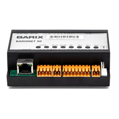
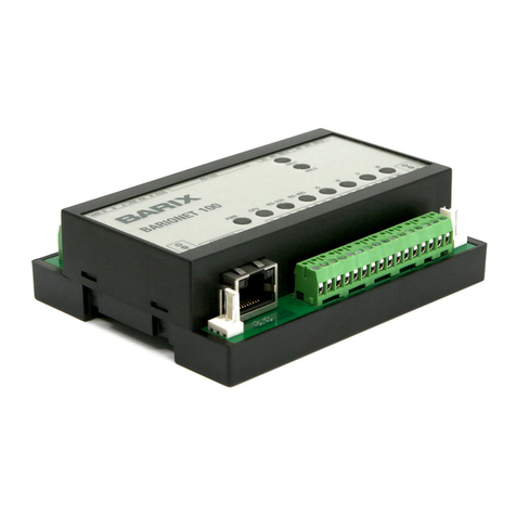
BARIX Barionet 1000 User manual

_____________________________________________________________________________
_____
_____
© Barix AG
7
/201
8
, all rights reserved. All information is subject to change without notice. All menti
oned trademarks belong to their
respective owners and are used for reference only. Barix, Exstreamer and SonicIP are trademarks of Barix AG, Switzerland, and
are
registered in certain countries.
__________________________________________________________________________________
BARIONET
1000
Quick Install Guide
Version
V
2
.
1
(
FW B1000
-
2.
2
.0.
0
)
__________________________________________________
_______________________________
IP & Wi
-
Fi Automa
tion Controller
Package contents
a
Barionet
1000
b
3 Female Terminal Blocks
c
Sticker with Wi
-
Fi and LAN MAC Address
Mounting on a DIN Rail
Slide the device upwards onto the DIN rail. Push it up and towards the rail until it snaps onto the upper
rail edg
e.
Before powering the device please read this quick install guide and mind the polarity of the
power supply (see picture on page 2).
Firmware
This devices comes preloaded with a default OpenWrt image with drivers for the Barionet Hardware. A
Python and L
ua Interpreter are pre
-
installed.
Newer or alternative Firmware can be downloaded from
www.barix.com/downloads
Support
For support please contact your local dealer or visit
www.barix.com

_____________________________________________________________________________
_____
_____
© Barix AG
7
/201
8
, all rights reserved. All information is subject to change without notice. All menti
oned trademarks belong to their
respective owners and are used for reference only. Barix, Exstreamer and SonicIP are trademarks of Barix AG, Switzerland, and
are
registered in certain countries.
__________________________________________________________________________________
Top View
Con1
2
x USB Host
Pin
Description
1
VCC (+5V)
2
D
–
(Data
-
)
3
D
+
(Data +)
4
GND
J
5
Relay Outputs
(
250VAC
,
5
A)
Pin
Desc
ription
1
Relay 2 common
2
Relay 2 normally open
3
Relay
2
normally closed
4
Relay
1
common
5
Rel
ay
1 normally open
6
Relay
1
normally
closed
J
1
I/O and Supply Inputs
Pin
Description
1
..4
Input 1..4 Analog 0..15VDC or Digital
5..8
Input 5..8 Di
gital
9
Common Inputs Ground
10..13
Output 1..4 Digital (Open Collector
0..24VDC, 100mA)
14
Common Outputs Ground
15
Power In +9..30VDC
16
Power In
-
P1
RS
-
232 serial port
Pin
Description
2
RxD (Receive data)
3
TxD (Transmit data)
5
GND (Ground
)
7
RTS (Ready to send)
8
CTS (Clear to send)
1,
4,
6,9
not connected
CON
2
Ethernet (RJ45)
Pin
Description
1
TX + (Transmit data)
2
TX
-
(Transmit data)
3
RX + (Receive data)
4
NC
5
NC
6
RX
–
(Receive data)
7
NC
8
NC
Left LED Yellow
-
Activ
ity
Left LED Green
-
Link / Speed (Blinking)
J
3
Dallas 1
-
wire® bus
Pin
Description
1
(DO NOT CONNECT)
2
Ground (GND)
3
1
-
wire data

_____________________________________________________________________________
_____
_____
© Barix AG
7
/201
8
, all rights reserved. All information is subject to change without notice. All menti
oned trademarks belong to their
respective owners and are used for reference only. Barix, Exstreamer and SonicIP are trademarks of Barix AG, Switzerland, and
are
registered in certain countries.
1.
Connecting to power and
initiali
z
ation
Power Supply
The Barionet
1000
needs a DC supply
voltage of 9V to 30V, 4W
max. Please mind
the polarity. When powered up,
the Status
LED of the CPU will start blinking, indicating
that the device is starting up.
Blue CPU LED:
Main CPU
When the device is initiali
z
ed,
the
PWR
Status LED
turn
s
solid, all other LEDs
will
turn off
(assuming no active IO is
connected).
2.
Connecting
via Ethernet
Plug
an
E
thernet cable from
the
Barionet
1
0
0
0
to an Ethernet network
.
The Barionet
10
00 is configured to be a
DHCP Client by default. Use a Network
Scanning Program in order to determine
the I
P Address according to the given MAC
Address.
3.
Changing Settings via Luci
Web Interface
Opening the LuCi Interface
To use the LuCI web interface please type
the IP address
of
the Device
of into
your
web browser:
e.g.
192.168.
1
.
123
The d
efault username
and password
is
:
Username:
root
Password:
(blank)
The root user has NO password set, so
make sure you set one !
C
hanging Network Settings
In the LuCI web interface
-
>
<
Network
>
you will find all relevant settings, so you can
set other IP addresses, enabl
e/disable
DHCP for each network port (Wi
-
F
i or
Ethernet), and also
enable
the
Wi
-
Fi
interface.
Make sure you don’t lock yourself out if you
change the settings !
C
ontrol IOs
In the LuCI web interface
-
>
<
Barionet
>
you
will find a
Control Interface to contr
ol and
monitor the GPIOs of the Barionet.
Simply click on the Control Buttons to
change the state of Rela
ys
and IOs.

_____________________________________________________________________________
_____
_____
© Barix AG
7
/201
8
, all rights reserved. All information is subject to change without notice. All menti
oned trademarks belong to their
respective owners and are used for reference only. Barix, Exstreamer and SonicIP are trademarks of Barix AG, Switzerland, and
are
registered in certain countries.
4.
Connecting
via Wi
-
Fi and SSH
Connecting via
Wi
-
Fi
T
he Wi
-
Fi Interface is turned
on by default
offering an SSID which is called
“Barione
t_”
and the four last digits of its MAC address
(for example, Barionet_
0024B5
).
The
security key/passphrase
“barionet”
is used
to protect the WLAN
.
Connect your PC to this Wi
-
Fi network.
For
this network, the Barionet works as a
DHCP server and uses the IP
Address
192.168.166.1 itself. For your PC, an IP
address in the 192.168.166.x range will be
assigned
.
For security reason, we recommend to turn
off the WLAN interface if it is not needed in
the Application. Use the LuCI Webinterface
-
>
<
Network
>
-
>
<
Wirel
ess
>
in order to
turn the Interface off.
Establishing an SSH Connection
Use ssh or a similar client (for example,
PuTTY, port 22, SSH option) and establish
a connection as user
“
root
”
to the IP
address of the Barionet (
given
DHCP
Address
if connecting v
ia Ethernet
or
192.168.166.1 if connect
ed
via Wi
-
F
i)
.
The root user has NO password set, so
make sure you set one !
5.
Installing OpenWRT Packages
OpenWRT Packages can be installed by
the standard OpenWRT/Lede Package
installer by using “opkg” command
“opkg
list”
-
> lists all the available packages
“opkg list
-
installed”
-
> lists the installed
packages
“opkg update”
-
> updates the installed
packages
“opkg install <file>”
-
> installes a specific
package
6.
IO Access from Scrip
t
s or
programs
The IO ports are acce
ssible through the
standard OpenWrt IO device files.
The Device Files can be found in the folder
/
dev
/gpio.
Relay Outputs
Rela
y
Outputs:
bio1
–
bio2
U
se the following shell command in order to
control the relay outputs:
“
echo 1 >
bio1
/value
”
-
> set Relay 1
“echo 0
>
bio1
/value”
-
>
re
set
Relay 1
Digital Outputs
Digital
Outputs:
bio
101
–
bio
10
4
Use the following shell command in order to
control the
digital
outputs:
“
echo 1 >
bio101
/value
”
-
> set
Output
1
“echo 0
> bio101
/value”
-
>
re
set
Output
1
Digital Inpu
ts
Digit
al Inputs:
bio201
–
bio208
U
se the following shell command in order
to
read the digital input values:
“
cat
bio201
/value
”
-
> reads Input 1

_____________________________________________________________________________
_____
_____
© Barix AG
7
/201
8
, all rights reserved. All information is subject to change without notice. All menti
oned trademarks belong to their
respective owners and are used for reference only. Barix, Exstreamer and SonicIP are trademarks of Barix AG, Switzerland, and
are
registered in certain countries.
Analog
Inputs
Analog Inputs:
bio
50
1
–
bio
50
4
U
se the following shell command in order
to
read the
analog
input values:
“
cat
bio
50
1
”
-
> reads
Analog
Input 1
Make sure that Pull
-
Up Resistors on the
Analog Inputs are turned off for reading
analog values
7.
Use of Serial Ports from
Scrip
t
s or programs
The
Serial Ports (RS232 and RS485)
are
accessible through the st
andard OpenWrt
USB
device files.
The Device Files can be found in the folder
/dev
.
RS232 Interface
:
ttyS
1
Use the following shell command in order to
write to the Serial Port
:
“echo
hello world
>
tty
S
1
”
-
> writes to
RS232
Use the following shell command in
order to
read from the Serial Port
:
“
cat
ttyS
1
”
-
> reads from RS232
8.
Mounting a USB Stick
In order to mount a USB stick to the
OpenWRT File System, the following
packages need to be installed:
-
> kmod
-
usb
-
storage (Kern
el suppo
rt for
USB Mass Storage devic
es)
-
>
kmod
-
fs
-
vfat (support of the right file
system, vfat for fat32)
The USB Stick can now be plugged in and
mounted with mount command as
following:
“
mount
-
t vfat /dev/sda1 /mnt/usb
”
-
>
mounts the sda1 (first USB stick)
Note that “sda1” is eventuall
y replaced by
another interface. Use dmesg in order to
determine the right interface.
Note that the /mnt/usb directory needs to
be created before mounting.
9.
Use of Modbus
The Barionet 1000 is supporting Modbus
TCP Protocol in order to be controlled.
Modbus
Interface
:
TCP Port 502
All IOs as well as a lot of more functions are
accessible via Modbus IO Registers
according to Appendix 1) IO Mapping.
10.
Lua Programming
The Barionet 1000 can easily be custom
programmed in Lua. For more information
about Lua Progra
mming see www.lua.org.
A limited set of Lua Packages are pre
-
installed on the Barionet 1000 already.
Most of the common Packages can easily
be installed using OPKG packet installer
(see above).
Lua Programs can be loaded onto the
device using ssh and scp.
The Lua program
will be started using the following
command:
“lua helloworld.lua”
-
> starts helloworld.lua

_____________________________________________________________________________
_____
_____
© Barix AG
7
/201
8
, all rights reserved. All information is subject to change without notice. All menti
oned trademarks belong to their
respective owners and are used for reference only. Barix, Exstreamer and SonicIP are trademarks of Barix AG, Switzerland, and
are
registered in certain countries.
If a Lua Program needs to be started
automatically after startup of the device, the
program has to be named as “default.lua”
and copied to the fol
lowing directory:
-
>
/usr/bin/default.lua
11.
Reboot the Device
With LuCI Web Interface
On the LuCI
web interface go to the System
"
-
>
<
Reboot
>
S
elect
“Perform Reboot”.
With
Hardware Jumper
Remove the top part of the B1000 case.
Power the Device and wait until it has
started up
-
> Blue CPU LED turns solid.
Place the Factory Defaults Jumper and wait
at
least 10s.
Remove the Factory Defaults Jumper.
12.
Reset to factory defaults
With LuCI Web Interface
On the LuCI web interface go to
<
System
>
-
> <
Backup/Flash Firmware
>
Under Backup/Restore select
“
Reset to
defaults
” and p
erform
the factory reset.
At this
point, the device will reboot and
apply default settings.
At this point, the device will reboot and
apply default settings.
13.
Upload
Firmware Image
For Software updates
a
complete
OpenWRT/LEDE Image is provided by
Barix. For new updates see
www.barix.com/downloads
.
The easiest way is to update the Firmw
are
using the LuCI Webinterface:
<
System
>
-
>
<
Backup / Flash Firmware
>
.
Make sure the “Keep Settings” option is not
selected, this ensures that the Device is
corr
ectly set back to Factory Defaults after
the Firmware Update.
Please note that all Settings, user programs
etc. are deleted after a Firmware Update.
Be patient during the Software update and
do not disconnect the Power Supply. The
Software Update can Take
up to 5 Minutes.

_____________________________________________________________________________
_____
_____
© Barix AG
7
/201
8
, all rights reserved. All information is subject to change without notice. All menti
oned trademarks belong to their
respective owners and are used for reference only. Barix, Exstreamer and SonicIP are trademarks of Barix AG, Switzerland, and
are
registered in certain countries.
Appendix 1) IO Mapping
The following Table shows the IO Mapping for the Barionet 1000
with its associated IO
addresses and functions:
IO Addr
Read/Write
Size
Description
Driver Alias
Driv
er Link
1
R / W
1 bit
Relay 1
rel1
bio1
2
R / W
1 bit
Relay 2
rel2
bio2
10..
100
R / W
1 bit
Virtual IO Bits
101
R / W
1 bit
Digital Output 1
out1
bio101
102
R / W
1 bit
Digital Output 1
out2
bio102
103
R / W
1 bit
Digital Output 1
out3
bio103
104
R / W
1 bit
Digital Output 1
out4
bio104
10
5
..
200
R / W
1 bit
Virtual IO Bits
201
R only
1 bit
Digital Input 1
in1
bio201
202
R only
1 bit
Digital Input 2
in2
bio202
203
R only
1 bit
Digital Input 3
in3
bio203
204
R only
1 bit
Digital In
put 4
in4
bio204
205
R only
1 bit
Digital Input 5
in5
bio205
206
R only
1 bit
Digital Input 6
in6
bio206
207
R only
1 bit
Digital Input 7
in7
bio207
208
R only
1 bit
Digital Input 8
in8
bio208
2
0
9
..
400
R / W
1 bit
Virtual IO Bits
501
R only
1
6
bits
Analog Input 1 Value
analog1
bio501
502
R only
16
bits
Analog Input 2 Value
analog2
bio502
503
R only
16
bits
Analog Input 3 Value
analog3
bio503
504
R only
16
bits
Analog Input 4 Value
analog4
bio504
505
..
600
R / W
16
bits
Virtual IO Regist
ers
701
..
1000
R / W
16
bits
Virtual IO Registers
60101
R / W
1 bit
Pull
-
Up Digital Input 1
pullup1
bio60101
60102
R / W
1 bit
Pull
-
Up Digital Input 2
pullup2
bio60102
60103
R / W
1 bit
Pull
-
Up Digital Input 3
pullup3
bio60103
60104
R / W
1 bi
t
Pull
-
Up Digital Input 4
pullup4
bio60104
60105
R / W
1 bit
Pull
-
Up Digital Input 5
pullup5
bio60105
60106
R / W
1 bit
Pull
-
Up Digital Input 6
pullup6
bio60106
60107
R / W
1 bit
Pull
-
Up Digital Input 7
pullup7
bio60107
60108
R / W
1 bit
Pull
-
Up Di
gital Input 8
pullup8
bio60108
This manual suits for next models
1
Table of contents
Other BARIX Controllers manuals
Popular Controllers manuals by other brands

INSTEON
INSTEON 2477SA1 owner's manual

ICOP Technology
ICOP Technology QEC-M-043T user manual

M&S Armaturen
M&S Armaturen PAMS NC/NO Series Operation manual

Vacon
Vacon 100X series Installation and maintenance manual

TREND
TREND NBOX(B)/CNC2 installation instructions

Amada
Amada VL Series operating instructions