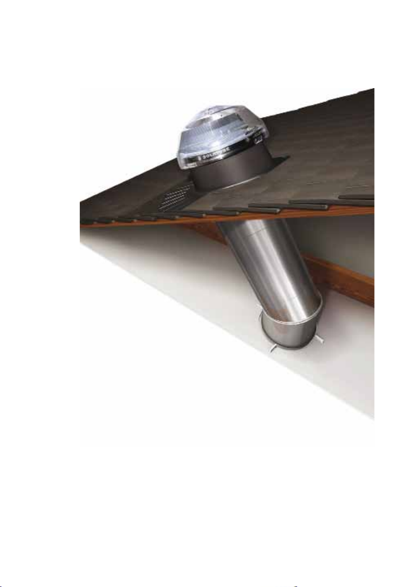
Solatube Brighten Up 160 DS User manual

Solatube
Brighten Up®
Series -
Solatube® 160 DS (250mm)
Solatube® 290 DS (350mm)
Step-by-step
installation guide for
pitched and flat roofs

Solatube® Daylighting Systems
Solatube® Daylighting Systems are the brightest way to bring daylight
into your home.
Solatube® Daylighting Systems incorporate innovative technologies
that deliver unrivalled levels of natural light. We are so confident that
no other tubular daylighting device will give you more daylight – all
day long, all year long – than a Solatube® Daylighting System, we offer
a money-back guarantee.
For more information regarding the Solatube® Highest Performance
Guarantee or to register your Solatube® Daylighting System, please
visit our website at www.solatube.co.uk.

1
Welcome to a brighter world
• angle grinder/tile cutter
• drill and drill bits
• flat or spud-bar
• hammer
• reciprocating saw
• scissors or blade knife
• screwdrivers
• sealant gun
• tape measure
• wire brush
Suggested tools

2
Important Safety Information
Proceed with your Solatube® Daylighting System installation only if you have read and understood
these guidelines fully, including the safety points below.
Installation may require climbing and working at heights. Use extreme caution to minimise risk of
accidental injury and property damage, including, but not limited to:
• Clear the area below your workspace of all people, animals and other items
• Avoid working on surfaces that are slippery or wet and use appropriate footwear
• Use only strong, well-supported and appropriate equipment for working at height
• Work only in safe weather conditions
• When in attics, ensure your weight is supported by structurally sound framing
• Reduce the risk of fire, electric shock and personal injury by following basic safety precautions
when using electrical tools. Always wear safety goggles or other suitable eye protection and
ensure the work area is clear of all electrical wires, gas pipes, water pipes and any other obstacles
that may present a risk
• When working in attics use of a mask or respirator is recommended to avoid lung irritation
• Beware of sharp protruding objects and wear protective gloves to avoid lacerations
• Do not attempt installation without having someone within range of your voice or close enough
to come to your aid if necessary
• Only suitably qualified persons should undertake electrical wiring
• Ensure the roof is in an appropriate condition to support the work necessary to install your
Solatube® Daylighting System, without damaging its structure or waterproofing properties
• Long lengths of extension tube sections may be secured by wire or other retainers to the rafters
• To eliminate the possibility of condensation on the tubes and, particularly cold conditions, it is
recommended to wrap an insulating jacket around the outer diameter of the tubing
Please read the full Terms and Conditions of sale at www.solatube.co.uk. If you have any doubt
concerning your competence or expertise regarding any aspect of the installation, consult your
supplier or a qualified expert before proceeding. In addition, please check the Health & Safety
Executive website for advice on safe working at height http://www.hse.gov.uk. Installation is
carried out at your own risk.
For further product information and technical support please contact your Solatube® supplier.
www.solatube.co.uk

3
Components for a flat roof application:
• Roof dome with Raybender® 3000 technology LightTracker™ Reflector system
• Flat metal roof flashing with 150mm parallel up-stand
• 305mm long top tube assembly (with 0-30° angle adaptor and dome ring)
• 305mm long ceiling tube assembly (with 0-30° angle adaptor
and ceiling ring
assembly)
• Classic Vusion™ diffuser
• Aluminium tape, sealant
cartridge and all seals,
fixings and fastenings
• Neoprene flashing
insulator (not shown)
Components for a pitched roof application:
Solaflex Flashing Kit is required for
installation into a pitched roof -
regardless of the pitch and tile/slate type.
Other components
Additional 0-90° angle adaptors and
610mm long straight sections are
available for applications with a longer
distance between roof and ceiling.
For installations through voids in excess
of 400mm, please use the table below
to determine the number of extension
tubes required.
Up to 400mm 0 extension tubes
Up to 960mm 1 extension tube
Up to 1520mm 2 extension tubes
Up to 2080mm 3 extension tubes
Up to 2640mm 4 extension tubes
Up to 3200mm 5 extension tubes
Up to 3760mm 6 extension tubes
• Solatube® 160 DS
recommended maximum
tube length - 6 metres
• Solatube® 290 DS
recommended maximum
tube length - 9 metres

4
Pitched Roof Application (for flat roof applications see p11)
Before you start, ensure you have the Solaflex Flashing Kit, required for all pitched
roof installations, and sufficient extension tubes to cover your installation distance
(refer to the chart on page 3).
Positioning
Select the desired location for the ceiling diffuser
and roof flashing. Ensure the tube’s path from the
ceiling to the roof is free from any obstructions.
Note that you will be able to align the ceiling
and top tube assemblies by rotating the 0-30°
adjustable angle adaptors as required.
Carefully cut the appropriate sized aperture in the
ceiling, avoiding joists and any obstructions:
Install the ceiling tube assembly
Insert the ceiling tube assembly into the aperture
and turn the twist-lock fastening clamps clockwise
with a screwdriver to clamp the ceiling tube
assembly lightly in place (do not over tighten).
These clamps may be loosened later to allow
the ceiling tube assembly to be rotated to help
alignment with the top tube.
From within the roof void, select an appropriate
centre point position for the roof flashing to which
the ceiling tube assembly must align. Mark this
position so it can be located from the surface of the
roof.
Solatube®
160 DS
Solatube®
290 DS
375mm
diameter
275mm
diameter
Cut the ceiling aperture

5
On the roof, locate your marker, remove
sufficient tiles and position (but do not
fix) the roof flashing. Ensure the top edge
of the flashing is able to be secured to
a batten, as shown, and no rafters or
obstructions lie in the tube’s path.
Using the inside of the roof flashing up-
stand as a template, mark a circle onto
the roof felt and batten. If necessary, cut
the batten, then cut the roof felt in a star
shape so the felt can be folded upwards
after the tube assembly is in place.
Fix the Solaflex sheet to the underside of
the roof flashing using the metal bracket
as a clamp;
On the underside of the flashing, align
the pre-drilled holes in the flashing
with the pre-drilled holes in the
metal bracket, ensuring all holes align
correctly*. From the flashing side, screw
the flashing to the bracket using initially
only the two outer holes of the bracket,
then insert the Solaflex sheet between
the flashing and the bracket, pushing it
up to the screws. Screw through the two
remaining holes, thus firmly clamping
the Solaflex sheet to the flashing. Mold
the Solaflex sheet towards the up-stand.
* 180mm apart on 160 DS / 220mm apart on 290 DS
Roof flashing location
Cutting through the roof felt
Attach the Solaflex Flashing Kit
Note: image shows flashing before batten is removed

6
Secure the top of the roof flashing to
the selected batten with the screws
provided. Ensure the lower edge of the
flashing and the Solaflex sheet sits over
the tiles below.
Lift the Solaflex sheet and apply a
generous bead of the sealant (supplied)
on top of the tile where the Solaflex sheet
will sit so that it secures to the roof tile
profile when it is formed down.
Apply hand-pressure to form the Solaflex
flashing sheet to the profile of the tiles
below.
Ensure the flashing is clean and dry, then
peel away the protective backing film
from the Solafoam weather strip and
apply it to the roof flashing as shown.
The Solafoam weather strip should be
cut back so as not to protrude from
under the tiles when they are replaced.
For slate or thin tile roofs
The Solafoam weather strip is not required for slate or thin tile roofs. Instead, use the
sealant supplied to create a weather strip between the slates and the flashing.
Secure the roof flashing

7
Replace and secure the removed tiles
using the appropriate fixings (not
supplied). Ensure there is a firm seal
between the underside of the tile and the
Solafoam weather strip.
Note that the Solafoam weather strip may
be trimmed for lighter tiles if they do not
re-seat properly.
Cut the remaining tiles to fit around the
top of the flashing, ensuring there is a
minimum gap of 40mm between the tiles
and the up-stand to allow the Solatube®
roof dome to be fitted (see dome and
top tube assembly installation section for
more details on page 8). Ensure all the
replaced tiles are firmly in position and
watertight.
The images below illustrate how the finished installation should appear when
completed (may vary according to roof type).

8
Installing the top tube assembly
Insert the top tube assembly into the roof
flashing so that the neoprene gasket creates a
seal between the flashing and the dome ring. If
necessary, rotate the lower angle section to point
towards the ceiling tube assembly. Align the pre-
drilled dome ring screw holes with the pre-drilled
up-stand holes.
Screw the dome ring to the up-stand through
the pre-drilled holes using the screws provided
and remove the protective film from the inside
of the top tube assembly.
Never leave the protective film in place once
the top tube has been fitted.
Align the holes in the LightTracker™ dome
reflector with the tabs inside the dome and
push into position, ensuring the dome reflector
is locked into position. Peel the protective film
from the dome reflector surface.
Keeping the LightTracker™ dome reflector on
the north side of the dome facing south, align
the four locking tabs on the dome base with
the snaps on the dome ring. Press down firmly
until the dome locks into place. Ensure the tabs
are fully engaged.
Installing the roof dome

9
Installation within the roof void
Installing the flashing insulator
The flashing insulator is designed to reseal the
roofing felt or seal to the underside of a flat roof.
Slide the flashing insulator over the open end of
the top tube assembly and slide it towards the
flashing. Screw down or tape the edges of the
flashing insulator to the rafters and/or roof felt.
Connecting the top and ceiling assemblies
If extension tubes are used, remove the protective
film from the inside of the extension tube(s) before
assembly. Each extension tube has a deep and
shallow notch at each end, as well as a central
notch.
Weave one end of the tube through the deep
notch, and the other through the shallow notch,
ensuring the tube is also held by the centre notch.
At this stage, use small pieces of the aluminium
tape provided to hold the notches together.
Assemble the required length of extension tubes
to join the top tube to the ceiling tube, ensuring
a minimum of 50mm overlap between each
join. Use small pieces of tape to hold the tubes
together. Check the assembled tube length is
correct and fits into the top and ceiling tubes. All
extension tube joins can now be fully taped.
If using more than one extension tube, ensure
the smaller diameter tube end (deep notch) faces
towards the ceiling to allow any further tubes to
fit inside. Extension tubes can then be ‘telescoped’
together to provide the total length required.

10
Use the shiny side of the tape’s backing
paper to rub over the aluminium tape to
produce a smooth, well-bonded surface on
all joins.
On the uppermost extension tube, wrap
the self-adhesive expansion joint seal twice
around the outer diameter of the tube,
approximately 25mm from the top. If no
extension tubes are used, the expansion
join seal is applied to the ceiling tube
assembly.
Slide the extension tube(s) up into the top
tube assembly and gently ease back down
into the ceiling tube assembly, allowing
a 50mm overlap for both. If necessary,
adjust the angles of the top or ceiling tube
assemblies.
Once in place, seal ALL the remaining
seams and joins with the aluminium
tape provided.
For extra strength and rigidity, use the
small self-tapping screws to secure all joins.
Installing the clear lens & ceiling diffuser
With the clear pull tab facing downwards,
insert the clear lens up into the ceiling tube
assembly until its gasket locates into the
channel. Place the ceiling diffuser up into the
ceiling ring, matching the slots, and twist to
secure into place.

11
Flat Roof Application (for pitched roof applications see p4)
Before you start your installation, ensure you have sufficient extension tubes to
cover the installation distance (refer to chart on page 3). This section of the guide
shows a retrofit installation into a felt roof. If your roof covering is being installed at
the same time as the Solatube® Daylighting System, it is possible to install the roof
flashing to the decking, with the felt or membrane covering the metal flashing/
upstand.
Positioning
Select the desired location for the ceiling diffuser
and roof flashing. Ensure the tube’s path from the
ceiling to the roof is free from any obstructions.
Note that you will be able to align the ceiling
and top tube assemblies by rotating their 0-30°
adjustable angle adaptors as required.
Carefully cut the appropriate sized aperture in the
ceiling, avoiding joists and obstructions:
Install the ceiling tube assembly
Insert the ceiling tube assembly into the aperture
and turn the twist-lock fastening clamps clockwise
with a screwdriver to clamp the ceiling tube
assembly lightly in place (do not over tighten).
These clamps may be loosened later to allow
the ceiling tube assembly to be rotated to help
alignment with the top tube.
Locate the centre point above the aperture in the
ceiling and mark the position for the roof flashing so
that it can be located from the rooftop.
Solatube®
160 DS
Solatube®
290 DS
375mm
diameter
275mm
diameter
Cut the ceiling aperture

12
At the centre point above the ceiling aperture,
sweep away any gravel or embedded grit from the
roof area where the flashing will be located. If the
roof is felt or roll roofing, remove any dirt or loose
granules with a wire brush. If the roof is hot-tarred
and gravel, scrape away the embedded gravel and
excess tar with a flat- or spud-bar. The roof surface
under the flashing and 75mm beyond the edge
must be smooth, level, clean and dry.
Drill eight additional 5mm diameter holes around
the edge of the flashing base between the eight
existing holes.
Centre the flashing over the centre point marker.
Using the inner circumference of the flashing as a
guide, mark a circle onto the roof surface. Remove
the flashing and cut 20mm inside the marked circle.
Clean any sawdust from around the roof aperture
and temporarily place the flashing and top tube
in position to check alignment before proceeding.
Mark around the outer edge of the flashing.
Apply several generous lines of sealant around the
underside of the flashing, 25mm in from the outer
edge. Re-position the flashing onto the outer edge
marks, ensuring that it is seated correctly and the
sealant has made a complete and watertight seal.
Ensure the flashing insulator makes contact with
the flashing to eliminate any condensation (refer to
page 9).
Screw the flashing in place, ensuring that the
sealant is compressed evenly around the underside
of the flashing. Screws should be firm, but not over
tightened. Smooth any sealant along the edges
of the flashing. Apply sealant to all screw heads. If
there is gravel on the roof, sweep it back over the
base of the flashing.
Proceed with top tube and dome installation as
detailed on page 8 to complete your installation.

13
Solatube® Electric Light Add-on Kit
Fits into your Solatube® Daylighting System to
provide the convenience of a switchable electric
light for night time use. The fitting must be
positioned 220mm distance from from the lower
lens. Edison screw fitting and rated up to 75w,
may be used in conjunction with the Bathroom
Ventilation Kit to provide a neat 3-in-1 system.
Solatube® Daylight Dimmer™
The Solatube® Daylight Dimmer™ gives
complete control of the amount of light
entering the room. Ideal for bedrooms or
entertainment areas, the electronically
operated butterfly valve is integrated into
the Solatube® Daylighting System and can be
operated from a low-voltage, wall-mounted
switch or a remote control.
Solatube® Bathroom Ventilation Kit
Available for the Solatube® 160 DS only,
this innovative accessory not only delivers
excellent ventilation, it also provides a neat
and stylish 2-in-1 unit. Ideal for use in wet
rooms, shower rooms, bathrooms and en-
suites. Requires a roof void clearance of at
least 500mm. May also be used in conjunction
with the Solatube® Electric Light Add-on Kit.
Solatube® accessories
Solatube® 0-90o Angle Adaptor
In more complex installations with unusual
corners and obstructions, it may be necessary
to make further turns in the tube. The 0-90°
angle adaptor simply twists from a straight
tube through to a full 90° bend. Made from
99.7% reflective Spectralight® Infinity tubing.

Highest Performance Guarantee
We are so confident that no other tubular daylighting system will give you
more light – all day long, all year long – than a Solatube® Daylighting System,
we offer a money-back guarantee.
For more information please contact your
Solatube® supplier or visit our website at
www.solatube.co.uk.
Guaranteed quality and performance
www.solatube.co.uk
10 year product warranty
Solatube® manufacturers guarantee that all non-
electrical component parts of Solatube® Daylighting
Systems are free from defects for 10 years from initial
purchase date. Electrical options come with a 5-year
warranty from initial purchase date.
You can register your Solatube® product warranty online
at www.solatube.co.uk.
Other manuals for Brighten Up 160 DS
1
This manual suits for next models
1
Table of contents
Popular Ventilation Hood manuals by other brands

Baumatic
Baumatic BT98SS user manual

Indesit
Indesit IHT6.5CMIX Service information

KOBE
KOBE CH9130SQB Installation instructions and operation manual

Sirius Satellite Radio
Sirius Satellite Radio SLTC EM 97 900 installation instructions

Broan
Broan 88000 installation instructions

CONSTRUCTA
CONSTRUCTA CD669863 instruction manual