14
○○○○○○○○○○○○○○○○○○○○○○○○○○○○○○○○○○○○○○○
○○○○○○○○○○○○○○○○○○○○○○○○○○○○○○○○○○○○○○○○○○○○○○○
GB
○○○○○○○○○○○○○○○○○○○○○○○○○○○○○○○○○○○○○○○○○○○○○○○
INSTALLATION
This canopy hood is designed to be fixed to any rigid vertical surface, over a gas or
electric hotplate and can be used either in the extraction mode (ducted to the outside) or
in the recirculation mode (internal recycling).
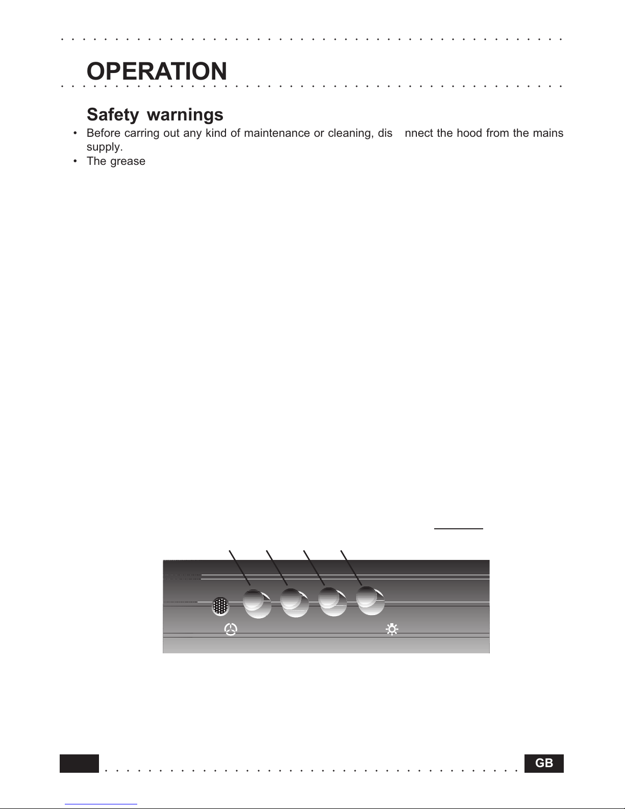
Safety warn ngs
• Before commenc ng the nstallat on, cons derat on should be g ven to the d ff cult es
to be found dur ng nstallat on and to the bulky we ght of the hood. The nstallat on
work must be undertaken by a qual f ed and competent person n conform ty to the
rules concern ng the evacuat on of contam nated a r. The manufacturer d scla ms all
l ab l ty for any damage or njury caused as a result of not follow ng the nstruct ons
for nstallat on conta ned n the follow ng text.
• When used n the extract on mode the cooker hood duct ng must not be connected to
a flue wh ch s used for exhaust ng fumes from appl ances suppl ed w th energy other
than electr c such as a central heat ng flue or water heat ng flue.
• When stalled, the hood must be pos t oned at least 65 cm above a cook ng appl ance.
• Never do flambé cook ng under th s cooker hood.
• Never leave fry ng pans unattended dur ng use as overheated fats and o ls may catch
f re.
• If the room where the cooker hood s to be used conta ns a fuel burn ng appl ance
such as a central heat ng bo ler then th s must be of the room sealed or balanced flue
type. If other types of flue or appl ance are f tted ensure that there s an adequate
supply of a r nto the room. When the cooker hood s used n conjunct on w th other
appl ances suppl ed w th energy other than electr c, the negat ve pressure n the room
must not exceed 0,04 mbar to prevent fumes be ng drawn back nto the room by the
cooker hood.
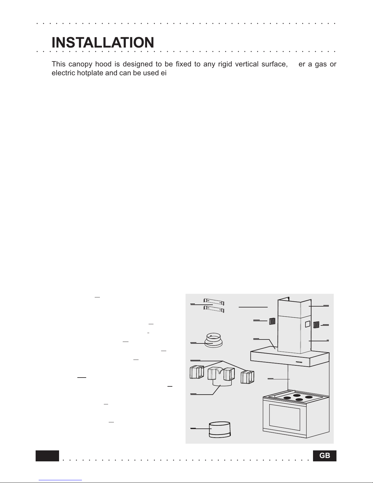
Components
The hood comprises the following (f g.1):
• No.1 canopy C complete with controls,
lighting and ventilator unit
• No.1 telescopic chimney, comprising:
No.1 upper chimney element S
No.1 lower chimney element I
• No.2 directional grills G
• No.1 reduction flange Ø 150-120 A
• No.1 recirculation spigot R
• No.2 additional side recirculation
spigots P1
• No.1 additional recirculation spigot P
• No.1 bag containing:
No.2 brackets 2 to fix the chimney,
screws, rawl plugs and documents.
• No.1 splashback B (optional)