SolaX Power BAT SYS-HV 5.0 User manual
Quick Installation Guide
—— Triple Power Lithium-ion Battery
100 Ah
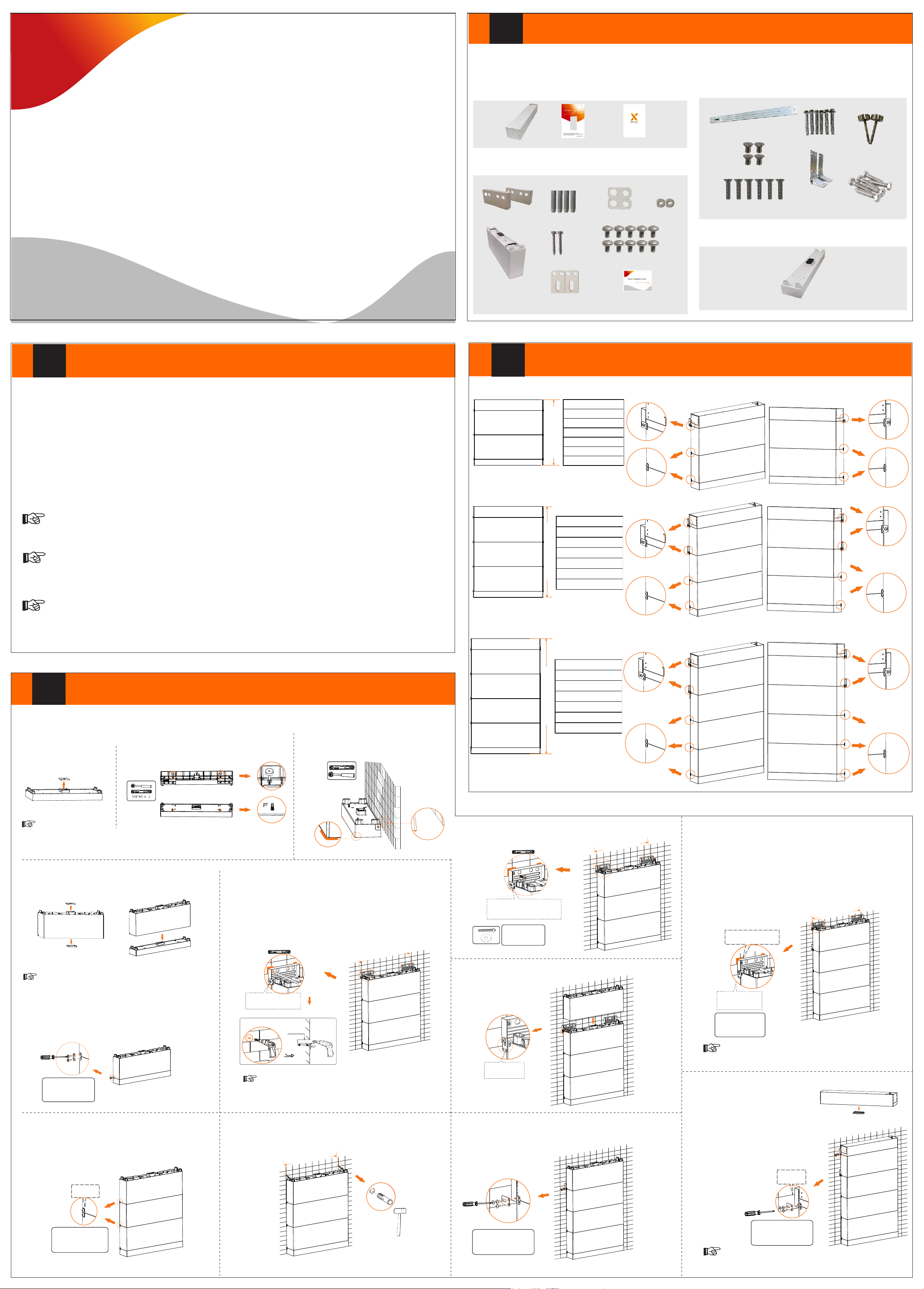
Packing List
I
Note: The Quick Installation Guide briefly describes required installation steps. If you have any question, please refer to the User
Manual delivered with the BMS for details.
BMS (TBMS-MCS60060):
OneBattery Module (TP-HS50×1):
Wall Bracket x 2
Expansion Sleeve x 4
Tapping Screw x 2
Shim Ring x 2
M5*10 Phillips-head Screw x 10
All Accessories Required for Two Installation Modes
Adjustment Screw x 2 Base Support x 2 Transverse Plate x 1 Expansion Bolt x 6
M5*8 Countersunk Head Screw x 4
M5*20 Countersunk Screw x 6
Platen (3 holes) x 2
Platen (2 holes) x 2
II Installation Prerequisites
Ensure that the installation location meets the following conditions:
The building is designed to withstand earthquakes
The location is far the sea to avoid salt water and humidity, over 3280.84 ft/1000 mfrom
The floor is flat and level
There are no flammable or explosive materials, at a minimum of 2.95 ft/0.9 m
The ambience is shady and cool, away from heat and direct sunlight
The temperature and humidity remain at a constant level
There is minimal dust and dirt in area
There are no corrosive gases present, including ammonia and acid vapor
Where charging and discharging, the ambient temperature ranges from 32℉/0°C to 113℉/45°C
ŸŸŸŸŸŸŸŸŸŸ
Ÿ
Ÿ
Ÿ
Ÿ
Ÿ
Ÿ
Ÿ
Ÿ
In practice, the requirements of battery installation may be different due to enviroment and locations.
In that case, follow up the exact requirements of the local laws and standards.
The Triple Power battery module is rated at IP65 and thus can be installed outdoors as well as indoors. However, if installed outdoors, the
battery pack shall not be exposed to direct sunlight and moisture.
Note!
If the ambient temperature exceeds the operating range, the battery pack will stop running to protect itself.
The optimal temperature range for operation is 14℉/-10°C to 122℉/50°C. Frequent exposure to harsh temperatures may deteriorate its
performance and lifetime.
Note!
For the first installation, the interval among manufacture dates of battery modules shall not exceed 3 months.
Note!
III Overview (Floor Mounting)
Scheme A
Scheme B
Scheme C
BMS
Battery
Battery
Base
Distance from the equipment:
To left side: ≥11.81 in./300 mm
To right side: ≥11.81 in./300 mm
BMS
Battery
Battery
Base
31.81 in./808 mm
2 * Wall Bracket
2 * Expansion Bolt
2 * Tapping Screw
2 * Gasket
14 * M5*10 Screws
2 * Platen (3 holes)
4 * Platen (2 holes)
Distance from the equipment:
To left side: ≥11.81 in./300 mm
To right side: ≥11.81 in./300 mm
4 * Wall Bracket
4 * Expansion Bolt
4 * Tapping Screw
4 * Gasket
20 * M5*10 Screw
4 * Platen (3 holes)
4 * Platen (2 holes)
BMS
Battery
Battery
Base
Battery
43.62 in./1,108 mm
BMS
Battery
Battery
Base
Battery
Distance from the equipment:
To left side: ≥11.81 in./300 mm
To right side: ≥11.81 in./300 mm
4 * Wall Bracket
4 * Expansion Bolt
4 * Tapping Screw
4 * Gasket
24 * M5*10 Screw
4 * Platen (3 holes)
6 * Platen (2 holes)
BMS
Battery
Battery
Base
Battery
Battery
55.43 in./1,408 mm
BMS
Battery
Battery
Base
Battery
Battery
Steps (Floor Mounting)
IV
Step 2: Locate the Base 1.57 in./40 mm away from the
wall, accurately mark the location of the Base on both
sides with a pen.
Step 1: Place Base.
(1) Remove the dust cover.
(2) Insert M8*85 screws from the bottom of Base, to
ensure that the Base is even.
(a) Use a spirit level to measure the sides of the Base to ensure they are even.
(b) If not, please adjust the Adjustment Screws by a torque wrench being to ensure that the Base
is even.
Note!
Step 3: Place Battery Module on the Base.
(1) Remove the top and bottom dust covers.
(2) Place the Battery Module on the Base.
Please reserve enough distance from the equipment to the ceiling/ground for capacity expansion.
Take Scheme C as an example.
Right View
1.57 in
40 mm
1.57 in.
40 mm
Mark
(3) Fix the Platen (2 holes) using M5 * 10 Phillips-head screw, and
secure M5*10 screws at both sides (Torque: 1.0 N·m).
Step 4: Place two Battery Modules in turn, and secure both left and
right sides using M5*10 countersunk screws (Tighten torque: 1.0
N·m). Refer to the Step 2 (3).
Please secure Platen and M5*10 screws immediately after placing a
Battery Module.
Platen (2 holes) × 2
M5*10 Screw × 4
1.0 N·m
Step 3 (3)
Platen (2 holes) × 4
M5*10 Screw × 8
1.0 N·m
Step 5:
(1) Attach M5 * 10 screw to Wall Bracket but be sure not to tighten;
(2) Place Wall Bracket to the wall, align its holes to the holes on the Battery,
and use a spirit level to ensure it's even;
(3) Accurately mark the location of the Wall Bracket on both sides;
(4) Circle along the inner ring of the holes;
(5) Remove the Wall Bracket, and then drill the two holes (at least 3.54 in./90
mm) by a Drill (φ 0.39 in./10 mm).
Attach screw but not
tighten
Mark
Electric drill dust collector is recommended.
Note!
(1) (2)
If the Base is shifted after placing a Battery Module, move it to its
original location according to the mark previously drawn.
Note!
Step 6: Place Expansion Bolts.
Step 7: Place the Wall Bracket on the wall where the mark is drawn
previously, and secure it using Tapping Screws and Gaskets.
32 in./812.80 mm
Tapping Screw × 2
Gasket × 2
Wall Bracket × 2
Attach screw but not
tighten, and align the hole
location of battery
32 in./812.80 mm
Mark
Step 8: Place the fourth battery module.
Let the Platen
down
Step 9: Fix the Platen (3 holes), and tighten M5*10 screws on both sides
(Torque: 1.0 N·m).
Platen (3 holes) × 2
M5*10 Screw × 6
1.0 N·m
Step 11: Place BMS on the Battery Module.
(1) Remove the bottom dust cover.
Electric drill dust collector is recommended.
Note!
Step 10:
(1) Attach M5 * 10 screw to Wall Bracket but be sure not to tighten;
(2) Place such Wall Bracket to the wall, align its holes to the holes on the
Battery Module, and use a spirit level to ensure it's even;
(3) Accurately mark the location of the Wall Bracket on both sides with a pen;
(4) Circle along the inner ring of the holes;
(5) Remove the Wall Bracket, and drill two holes (at least 3.54 in/90 mm) by a
Drill (φ 0.39 in./10 mm);
(6) Place Expansion Bolts;
(7) Secure Wall Brackets. Refer to the Steps 5, 6, 7 and 8.
32 in./812.80 mm
Step 5, 6, 7 and 8
Let the Platen
down
Step 9
Platen (3 holes) × 2
M5*10 Screw × 6
1.0 N·m
Tapping Screw × 2
Gasket × 2
Wall Bracket × 2
32 in/812.80 mm
Mark
(2) Place BMS, fix the Platen (3 holes) on
both sides, and then tighten M5*10 screws
(Torque: 1.0 N·m). Refer to Step 9.
Documentation x 1
BMS
Battery
Battery
Base
BMS
Battery
Battery
Base
Battery
BMS
Battery
Battery
Base
Battery
Battery
The holes on BMS is for secure inverter. For details, please refer to A1-
ESS-G2 User Manual.
Note!
32 in/812.80 mm
BMS x 1 User Manual x 1
Battery Module x 1
Expansion Bolt x 4
Wall Bracket x 2 Gasket x 2
Platen (2 holes) x 2
Tapping Screw x 2 M5*10 Phillips-head Screw x 10
Platen (3 holes) x 2 Quick Installation Guide x 1
Base Support x 2
Expansion Screw x 6
Transverse Plate x 1
M5*8 Countersunk Head Screw x 4
M5*20 Countersunk Screw x 6
Adjustment Screw x 2
Self-tapping Screw x 6
Base for BAT50-G2 Battery:
Base x 1
Φ 0.39 in./10 mm
for Wall Bracket
≥ 3.54 in./
90 mm
Safety Instructions x 1

VOverview (Wall Mounting)
Scheme A
Distance from the equipment:
To left side: ≥ 11.81 in./300 mm
To right side: ≥ 11.81 in./300 mm
To the ground : > 23.62 in./600 mm (The distance is reserved for increase of battery, and a battery’s height is 11.81 in./300 mm.)
Scheme A
2 * Wall Bracket
2 * Expansion Bolt
2 * Tapping Screw
2 * Gasket
14 * M5*10 Screw
2 * Platen (3 holes)
4 * Platen (2 holes)
BMS
Battery
Battery
Base
31.81 in./808 mm
BMS
Battery
Battery
Base
Scheme B
BMS
Battery
Battery
Base
Battery
Distance from the equipment:
To left side: ≥ 11.81 in./300 mm
To right side: ≥ 11.81 in./300 mm
To the ground: > 11.81 in./300 mm (The distance is reserved for increase of battery, and a battery’s height is 11.81 in./300 mm.)
4 * Wall Bracket
4 * Expansion Bolt
4 * Tapping Screw
4 * Gasket
20 * M5*10
4 * Platen (3 holes)
4 * Platen (2 holes)
43.62 in./1,108 mm
BMS
Battery
Battery
Base
Battery
Scheme C
Distance from the equipment:
To left side: ≥ 11.81 in./300 mm
To right side: ≥ 11.81 in./300 mm
To the ground: It shall be decided according to the local regulations.
4 * Wall Bracket
4 * Expansion Bolt
4 * Tapping Screw
4 * Gasket
24 * M5*10
4 * Platen (3 holes)
6 * Platen (2 holes)
BMS
Battery
Battery
Base
Battery
Battery
55.43 in./1,408 mm
BMS
Battery
Battery
Base
Battery
Battery
Steps (Wall Mounting)
VI
Please reserve enough distance from the equipment to the ceiling/ground for capacity expansion.
Take Scheme C as an example.
Step 1: There are two ways to install Transverse Plate to Base Support due to 4 kinds of Stub Spacing, with details as follows: (a) 28 in./711.20 mm or 32
in./812.80 mm; (b) 20 in./508.00 mm or 24 in./609.60 mm.
(1) Insert Transverse Plate to Base Support;
(2) Secure the Transverse Plate and Base Support using screws (2×M5*8 countersunk head screw) (Tighten torque: 2.2-2.5 N·m). See figure below.
Platen (2 holes) × 2
M5*10 Screw × 4
1.0 N·m
Step 7:
(1) Attach the M5 * 10 screw to Wall Bracket but be sure not to tighten;
(2) Place such Wall Bracket to the wall, align its holes to the holes on the Battery
Module, and use a spirit level to ensure it's even;
(3) Accurately mark the location of the Wall Bracket on both sides with a pen;
(4) Circle along the inner ring of the holes;
(5) Remove the Wall Bracket, and then drill the two holes (at least 3.54 in./90 mm) by
a Drill (φ 0.39 in./10 mm).
Electric drill dust collector is recommended.
Note!
Step 8: Place Expansion Bolts into the two holes (the Expansion Bolt is not required in
case of solid wood wall).
32 in./812.80 mm
VII Wiring
① Insert the orange power line into the orange socket
② Insert the black power line into the black socket
③ Screw the communication line into the communication socket
Before wiring,
1. Unscrew the cap at BMS clockwise;
2. Unscrew the screws at BAT+ and BAT- respectively.
After wiring
①②
③
DIP
BMS
BAT+ BAT-
POWER
VIII
Commissioning
If the batteries have not been used for more than 9 months, these batteries must be charged to at least SOC 50 % each time.
For the first installation, the interval among manufacture dates of battery modules shall not exceed 3 months.
If a battery is replaced or added for capacity expansion, each battery's SOC should be consistent. The max. SOC difference should be
between ±5%.
If users want to increase their battery system capacity, please ensure that the SOC of the existing system capacity is about 40%. The
manufacture date of the new battery shall not exceed 6 months; in case of exceeding 6 months, please charge the new battery to around
40%.
Black Start: Press the POWER button and hold it for 20 sec; release the button after the four SOC indicators flash blue alternately. But, we
do not recommend the use of Black Start as it may cause the port to be charged, resulting in an electric shock.
Steps for commissioning are shown as follows:
①Press the left side door panel
②Open the air switch's guard and toggle switch, to ensure that
the inverter does charge to the battery
③Press the right side door panel
④Press the button for 1 to 2 sec, and then the system starts
320102033203
Press the right side door panel
③
BMS
DIP
POWER
BAT-
BAT+
④
Press the left side door panel
①
②
The equipment can support capacity expansion.
There are two circumstances in case the user wants to increase a battery module:
1. For floor mounting, remove the inverter before increase of battery module;
2. For wall mounting, if the distance from the equipment to the ground is enough, do not remove the inverter; otherwise, the inverter shall
be removed.
BMS
Battery
Battery
Base
BMS
Battery
Battery
Base
Battery
BMS
Battery
Battery
Base
Battery
Battery
(1) (2)
Sequence 1 2 3 4 5 6 7 8
BMS //BMS_H BMS_L /A1 B1
GND
Making a BMS communication cable
To ensure normal operation of BMS and inverter, a BMS communication cable is
required to be made before wiring.
The specific definition of the communication cable is shown as follows:
The wire order of the communication cable is as follows:
1 2 3456 7 8
1) Orange stripes on white
2) Orange
3) Green stripes on white
4) Blue
5) Blue stripes on white
6) Green
7) Brown stripes on white
8) Brown
(a) (b)
32 in/812.80 mm
28 in/711.20 mm
20 in/508.00 mm
24 in/609.60 mm
Note: The bubble spirit level on the Transverse Plate can be used as an auxiliary tool, additionally, please prepare a spirit level to measure whether the Plate is even or not.
Step 12:
(1) Attach the M5 * 10 screw to Wall Bracket but be sure not to tighten;
(2) Place such Wall Bracket to the wall, align its holes to the holes on the
Battery Module, and use a spirit level to ensure it's even;
(3) Accurately mark the location of the Wall Bracket on both sides with a
pen;
(4) Circle along the inner ring of the holes;
(5) Remove the Wall Bracket, and then drill the two holes (at least 3.54
in./90 mm) by a Drill (φ 0.39 in./10 mm);
(6) Place Expansion Bolts;
(7) Secure Wall Brackets using Tapping Screws and Gaskets. Refer to the
Steps 7, 8, 9 and 10.
32 in./812.80 mm
Step 7, 8, 9 and 10
Let the Platen
down
Tapping Screw × 2
Gasket × 2
Wall Bracket × 2
32 in/812.80 mm
Mark
Electric drill dust collector is recommended.
Note!
Step 11: Fix the Platen (3 holes), and secure M5*10 screws on both
sides(Torque: 1.0 N·m).
Step 10: Place the fourth battery module.
Let the Platen
down
Platen (3 holes) × 2
M5*10 Screw × 6
1.0 N·m
Step 9: Place the Wall Bracket on the wall where the mark is drawn previously,
and then secure the Wall Brackets on the wall using Tapping Screws and
Gaskets.
32 in./812.80 mm
Tapping Screw × 2
Gasket × 2
Wall Bracket × 2
Attach screw but not tighten,
and align the hole location of
battery
Mark
Step 13: Place BMS on the Battery Module.
(1) Remove the bottom dust cover.
(2) Place BMS, fix the Platen (3 holes) on both sides, and then tighten
M5*10 screws (Torque: 1.0 N·m). Refer to Step 11.
Step 12
Platen (3 holes) × 2
M5*10 Screw × 6
2.2-2.5 N·m
The holes on BMS is for secure inverter. For details, please refer to A1-
ESS-G2 User Manual.
Note!
The BMS communication cable shall have a shield layer.
Note!
Step 2:
(1) Place the assembled Transverse Plate and Base Support on the wall, look
the cylindrical plastic bubble spirit level on the Transverse Plate. If the bubble
isn't in the center, slightly bow it to the horizontal.
(2) Then determine the position of holes.
(3) Mark it with a pen.
(4) Remove it and drill the four holes (at least 3.54 in./90 mm) by Drill (φ 0.47
in./12 mm for concrete wall, or φ 0.31 in./8 mm solid wood wall).
Note: In case of solid wood wall, please directly tighten the screws with
torque wrench instead of hammering them with rubber mallet.
Note: The distance from the Base to the ground is
decided according to the local regulations.
Ground
32 in./812.80 mm
Bubble
spirit level
Step 3:
(1) Place the assembled Transverse Plate and Base Support to the wall (or
solid wood stub);
(2) Attach the Expansion Screw to the holes but be sure not to tighten;
(3) Check whether the bubble spirit level is horizontal;
(4) Hammer Expansion Screws with a rubber mallet (except solid wood
wall), and tighten it with torque wrench.
Φ 0.31 in./8 mm
for Base Support
≥ 1.97 in./
50 mm
90º
Φ 0.47 in./12 mm
for Base Support
≥ 3.54 in./
90 mm
90º
(1) Concrete Wall
(2) Solid Wood Wall
Bubble
spirit level
32 in./812.80 mm
Φ0.47 in./12 mm
For concrete wall
x 4
Φ0.31 in./8 mm
For solid wood wall
x 4
M5*20 Screw × 4
2.2 - 2.5 N·m
32 in./812.80 mm
Step 4: Place the base.
(1) Remove the dust cover.
(2) Place Base on the Base Support and
secure both left and right sides with screws
(4 × M5*20 countersunk screw) (Tighten
torque: 2.2-2.5 N·m).
Step 5: Place Battery Module on the Base.
(1) Remove the top and bottom dust covers.
(2) Place the Battery Module on the Base.
(3) Fix the Platen (2 holes) using M5 * 10 Phillips-head screw, and
secure M5*10 screws at both sides (Torque: 1.0 N·m).
Step 6 (3)
Step 6 (3)
Platen (2 holes) × 4
M5*10 Screw × 8
1.0 N·m
Step 6: Place two Battery Modules in turn, and secure both left and
right sides with screws (4 × M5*20 countersunk screw) (Tighten
torque: 2.2-2.5 N·m). Refer to the Step 5 (3).
Please secure Platen and M5*10 screws immediately after placing a
Battery Module.
Attach screw but
not tighten
Mark
32 in./812.80 mm
Φ 0.39 in./10 mm
for Wall Bracket
≥ 3.54 in./
90 mm
This manual suits for next models
1
Other SolaX Power Camera Accessories manuals


