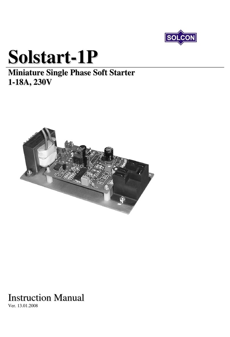
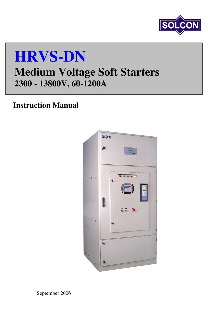
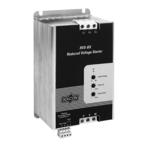
Solcon RVS-DN User manual

RVS-DN
Digital Soft Starter
8-3500A, 220-1000V
Instruction Manual
Ver. 12/10/2003

Table of Contents
Page Subject Appendix Page Subject
1 Starter Selection 39 Table of content
2 Installation 40 UL and cUL instructions, LR recommendations
3 By-pass contactor 41 Fuse selection
4 - 6 Control terminals 42 Motor and Starter Fault Occurrence Timing Table
7 Control terminals – Option Boards 43 Warranty claim sheet & Fault Inquiry
8 Control Wiring 44 Inside Delta Description
9-11 Wiring Diagrams 45 Overload Trip Time (Approximate calculation)
12-13 Wiring Diagrams – Communication 46-50 Dimensions and Weights
14 Wiring Diagrams – Diesel Generator 51 Block Diagram and Notes
15 Wiring Diagrams – Brake motor 52 Ordering Information
16-17 Internal setting
18-19 Start and stop parameters
20-21 Motor and starter protection
22-23 Front panel and LCD Displays
24 Display mode and Default Parameters
25-30 Parameter setting
31-32 Start-up and Pump Control adjustments
33-34 Menu Description
35-36 Trouble shooting
37-38 Technical specification
Safety
• Read this manual carefully before operating the equipment and follow its instructions
• Installation, operation and maintenance should be in strict accordance with this manual,
national codes and good practice. Installation or operation not performed in strict
accordance with these instructions will void manufacturer’s warranty.
• Disconnect all power inputs before servicing the soft-starter and/or the motor.
• After installation, check and verify that no parts (bolts, washers, etc) have fallen into the
power Section (IP00 for sizes B-G).
Attention
• This product was designed for compliance with IEC 947-4-2 for class A equipment.
• RVS-DN 8 - 820 are UL approved. RVS-DN 950 - 3500 are designed to meet UL requirements.
• RVS-DN 8 - 1400 are LR approved. RVS-DN 1800 - 3500 are designed to meet LR requirements.
• Use of the product in domestic environments may cause radio interference, in which case, the user may be
required to employ additional mitigation methods.
• Utilization category is AC-53a or AC53b. Form1. For further information, see Technical Specifications for
further details.
Warnings
• Internal components and P.C.B’s are at main potential when the RVS-DN is connected to main.
This voltage is extremely dangerous and will cause death or severe injury if contacted.
• When RVS-DN is connected to main, even if control voltage is disconnected and motors is
stopped, full voltage may appear on starter’s output and motor’s terminals.
• Unit must be grounded to ensure correct operation, safety and to prevent damage.
• Check that Power Factor capacitors are not connected to the output side of the soft starter.
The company reserves the right to make any improvements or modifications to its products without prior notice.

Starter Selection
1
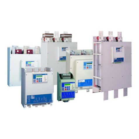
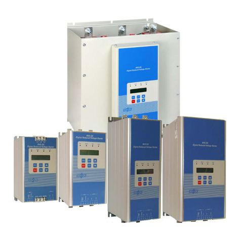
The RVS-DN is a highly sophisticated and reliable
starter designed for use with standard three-phase,
three-wire, squirrel cage induction motors. It provides
the best method of reducing current and torque during
motor starting.
The RVS-DN starts the motor by supplying a slowly
increasing voltage to the motor, providing soft start and
smooth acceleration, while drawing the minimum
current necessary to start the motor.
The second generation, microprocessor based digital
circuitry provides unique features like pump control,
slow speed, electronic reversing and accurate motor
protection, with optional Insulation Protection,
Thermistor input, etc.
The optional RS 485 Communication with MODBUS
protocol enables full control (Start, Stop, Dual Adjust,
command, etc.) and supervision. Up to 32 starters can
be connected on a shield twisted pair to a host
computer.
RVS-DN Ratings and Frame sizes
Max Motor FLA (Amp) Starter Type (FLC) Frame Size
8 RVS-DN 8 A
17 RVS-DN 17
31 RVS-DN 31
44 RVS-DN 44
58 RVS-DN 58
72 RVS-DN 72
85 RVS-DN 85 B
105 RVS-DN 105
145 RVS-DN 145
170 RVS-DN 170
210 RVS-DN 210 C
310 RVS-DN 310
390 RVS-DN 390
460 RVS-DN 460 D
580 RVS-DN 580
820 RVS-DN 820
950 RVS-DN 950
1100* RVS-DN 1100 E
1400* RVS-DN 1400
1800* RVS-DN 1800
2150* RVS-DN 2150 F
2400* RVS-DN 2400 G
2700* RVS-DN 2700
3000* RVS-DN 3000
3500* RVS-DN 3500
* Fully rated when used with a by-pass contactor
Dimensions (mm)
For exact dimensions, see Dimension Sheets.
Size Width Hei
g
ht De
p
th Wei
g
ht
(
K
g)
A 153 310 170* 4.5
,
6.0
,
7.5
B std. 274 370 222 15
B new 274 385 238 15
C 590** 500 290 45
D 623 660*** 290 65
E 723 1100 370 170
F 750 1300 392 240
G 900 1300 410 314
* 217mm – for 44, 58 & 72A
** 536mm – By special order, without side covers
*** Add 160mm for bypass bus-bars extension
The starter should be selected in accordance with the
following criteria (see Ordering Information data).
Motor Current & Starting Conditions
Select the starter according to motor’s Full Load
Ampere (FLA) – as indicated on its nameplate (even if
the motor is not fully loaded).
The RVS-DN is designed to operate under the
following conditions:
Max. ambient temp: 50ºC
Max. starting current: 400% motor’s FLA
Max. starting time: 30 sec. (at 400% FLA)
Max. starts per hour: 4 starts per hour at max
conditions. Up to 60 starts per hour at light load
applications.
Note: For very frequent starts (inching applications),
the inching current should be considered as the
Full Load Ampere (FLA).
Main Voltage (line to line)
Thyristor’s PIV rating, internal circuitry and insulation
defines four voltage levels: 220-440V, 575-600V
460-500V, 660-690V
Each starter is suitable for one of the above levels &
for 50/60 Hz.
Control Voltage
The Control Voltage operates the electronic circuitry
and fans. Two voltage levels are available:
220-240V + 10%-15%, 50/60 Hz (standard)
110-120V + 10%-15%, 50/60 Hz
110 Vdc for Frame size B-G (by special order).
Control Inputs
Control Input voltage (start, stop, etc.) can be the same
as Control Supply above (standard), or 24-240V AC /
DC (by special order).
Options (see Ordering Information Data)
• Communication Card (option # 3)
• Insulation Tester Card (option # 4)
• Analogue card-Thermistor in/Analogue out (option # 5)
• Special treatment – Consult factory (option # 8)
• Preparation for by-pass contactor (option # 9)
• Special width for size C-536 mm (option #A)
• Line/load bus-bars at the bottom, size C&D (option #B)
• Door install MMI instead of the original (option #D)
• Door install MMI w/op.#L&1.5m cable (option #DK)
• Back-lit LCD (option # L)
• Lloyds Register ENV-1, ENV-2 approval (option #M)
• Tachometer feedback (option # T)
• UL & cUL approvals (option # U)

Installation
2
Area (m2)
Prior to Installation
Check that Motor’s Full Load Ampere (FLA) is lower
than or equal to the starters Full Load Current (FLC)
and that Main and Control voltages are as indicated on
the front panel.
Mounting
• The starter must be mounted vertically, allow
sufficient space above and below the starter
for suitable airflow.
• It is recommended to mount the starter
directly on the rear metal plate for better heat
dissipation.
• Do not mount the starter near heat sources.
• Protect the starter from dust and corrosive
atmospheres.
Note: For harsh environments, it is recommended to
order the starter with Option # 8 – Special Treatment
(printed circuit board coating).
Temp. Range and Heat Dissipation
The starter is rated to operate over a temperature range
of -10ºC (14ºF) to + 50ºC (122ºF). Relative non-
condensed humidity inside the enclosure should not
exceed 95%.
Starter’s heat dissipation is approx. 3 x In (three times
the current in watts).
Example: For a 100A motor, heat dissipation is
approx. 300 watts.
Internal enclosure heating can be reduced through the
use of:
a. Additional ventilation
b. Employing a by-pass contactor.
Additional Ventilation
RVS-DN
General purpose enclosure
Fan on air outlet
RVS-DN
Non-ventilated enclosure
Fan, creating air circulation
Fan
Calculating the enclosure size, for non-ventilated
metallic enclosure:
Where Area (m2) - Surface area that can dissipate heat
(front, sides, top).
* Total heat dissipation of the starter and other control
devices in the enclosure.
Note: If the starter is installed in a non-metallic
enclosure, a by-pass contactor must be used.
Short Circuit Protection
Protect the starter against a short circuit by Thyristor
Protection Fuses (see appendix page 44 for I2t and
fuses).
Transient Protection
Line transient voltages can cause a malfunction of the
starter and damage to the thyristors. Starters frame
sizes B-E incorporate Metal Oxide Varistors (MOV to
protect from normal line voltage spikes.
For size A, or when higher transients are expected,
additional external protection should be used (consult
factory).
ATTENTION
When Start signal is initiated and a motor is not
connected to load terminals, the Wrong Connection
protection will be activated.
WARNING
1. When main voltage is connected to the
RVS-DN, even if control voltage is
disconnected, full voltage may appear on the
starter load terminals. Therefore, for
isolation purposes, it is necessary to connect
an isolating device before the starter.
2. Power factor correction capacitors must not
be installed on the starters load side. When
required, install capacitors on starter’s line
side.
WARNING
RVS-DN current transformers, although may be
installed outside of the soft-starter with extended
wires, can not be grounded or connected to any other
load except for the RVS-DN itself. Any such
connection may cause damage to the load which was
connected to it or to the RVS-DN itself!
0.12 x Total heat dissipation (Watts)*
60
–
External ambient temp. (
º
C)

By-pass Contactor
3
Under normal operating conditions, the heat dissipated
by an electronic soft starter causes heating of the
enclosure and energy losses. The heating and losses
can be eliminated by the use of a by-pass contactor,
which by passes the RVS-DN after completion of start-
up, so motor current will flow through the by-pass
contactor.
In this case the starter protection
will be maintained except for the
current protection, as the current
will not flow through the internal
current transformers after the by-
pass closes.
Preparation for By-pass Contactor (option)
In order to maintain current protection after the by-pass
contactor closes, Preparations for By-pass Contactor
can be ordered.
Frame Size A (8 – 72A)
Must be factory supplied, three
additional terminals are added,
marked L1b, L2b, L3b.These
terminals are connected after the
internal C/Ts, intended for
connection to the by-pass.
M
UVW
L1
b
L2
b
L3
b
L3L1 L2
Frame Sizes B (Standard and New 85-170A)
Old – Additional set of bus-bars can be field mounted
on the line side, after the C/Ts, marked L1b, L2b, L3b.
New – Additional set of bus bars is built-in, where the
line side is on top and motor side is at the bottom with
the by-pass
L1b, L2b, L3b terminals are located. By-pass contactor
cables should be connected to these terminals.
L1
bL2
bL3
b
L3L1 L2
UVW
Built in
C/T'
M
L1
bL2
b
L3
b
L3L1 L2
M
C/T
U V W
Frame Size C
(210 - 390A)
Additional set of bus
bars can be field
mounted on line side,
after the C/T’s marked
L1b, L2b, L3b. Bypass
cables should be
connected to these
terminals.
L2b
L3b
M
L1b
U L1 V L2 W L3
Frame Size D
(460 - 820A)
Additional set of bus
bars can be field
mounted on line side,
downstream to the
C/T’s marked L1b, L2b,
L3b. Bypass cables
should be connected to
these bus-bars.
L2b
L3b
M
L1b
U V W
L3L1 L2
C/T C/T
Note: Starter frame sizes C and D can be field modified
to have Line and Load Bus-bars at the bottom (consult
factory for further information).
Frame Size E
(1100 – 1800A)
Frame Size F
(2150A)
Frame Size G
(2400 – 3500A)
Additional set of bus-bars
can be field mounted on line
side, down stream to the
C/Ts, marked L1b, L2b, L3b.
By-pass cables should be
connected to the bus-bars
down stream to the C/T’s
Note: Connect as follows
• Line to L1, L2, L3
• By-pass
Input to L1b, L2b, L3b
Output to U, V, W
• Motor (Load) to U,V,&
W
C/T
L1
M
U V W
L1bL2bL3b
C/T
L2 L3
Do not interchange line and load connections.
M
By Pass
Contactor
RVS-DN

Control Terminals
4
Control Supply Terminals 1-3
110-120VAC or 220-240VAC, 50/60Hz as indicated
on the front panel, required to power the electronic
circuitry and fans when incorporated. This voltage can
be from a grounded or ungrounded main system.
110VDC can be supplied by special order for starter
sizes B-G (not field interchangeable).
Note: It is recommended that terminals 1-3 be
always connected to the Control Supply.
Fan’s Supply Voltage Terminal 2
An internal jumper, connected between fan and
terminal 2 enables three modes of operation (see Fan
Control – page 16). For fan power consumption, see
technical specification.
Continuous mode (factory default) – Fan operates as
long as Control Supply is connected to terminals 1-3.
Leave internal jumper connected to left lug of JI
terminal (A).
External control mode – Fan operates when Control
Supply is connected to terminal 2. Connect internal
jumper to the center lug of JI terminal (B). For use
without by-pass, connect fans before “start” and
disconnect at least 5 minutes after “Stop/Soft-stop”.
Automatic mode – Fan begins operation when start
signal is initiated and stops approximately five minutes
after start signal. When stop signal is initiated, the fan
begins operation and stops after five minutes. Connect
internal jumper right lug of JI terminal (C).
WARNING
Automatic mode may be used only if by-pass
contactor is directly controlled by the RVS-DN “End-
of-Acceleration” contact.
1-3 4-9 10-21 22-24 25-32
I/O Terminals
Internal Fan
Terminals
Control Inputs
Incorporating opto-couplers to isolate the micro-
processor circuitry.
The starter is supplied standard for 220-240V, 50/60Hz
Control Supply and Control Inputs voltage.
By special order, Control Inputs may be supplied for
voltage levels of 24-240 VAC/DC. (for more
information, see Ordering Information data – Appendix
page 48).
Stop Terminal 4
Input from a N.C contact. To stop the motor,
disconnect control voltage from Terminal 4 for at least
250mSec.
Soft stop Terminal 5
Input from a N.C contact. To soft stop the motor,
disconnect control voltage from Terminal 5 for at least
250mSecs.
Note: If Soft Stop is not required, connect a
jumper between terminals 4 and 5.
Start Terminal 6
Input from a N.O contact. To start the motor, connect
control voltage to Terminal 6 for at least 250mSecs.
Notes:
1. Motor will start only if Stop (4) and Soft Stop
(5) terminals are connected to control voltage.
2. Reset after a fault is not possible for as
long as Start command is present.
Energy Save / Slow Speed / Reset Terminal 7
Input from a N.O contact. Selection between above
functions is made from the keypad or through the
communication (see I/O Programm.)
• When Energy Save function is selected –connect
terminal 7 to control voltage by a jumper for
automatic operation, upon load decrease.
When connected through a N.O contact, closing the
contact operates Energy Save.
• When Slow Speed function is selected – connect
control voltage to terminal 7 before starting, to run
the motor at 1/6 nominal speed. Closing terminal 7
while motor is running will not have any effect.
• When Reset function is selected, connect terminal 7
to control voltage (use a N.O momentary contact) to
reset the starter.

Control Terminals
5
Dual Adjust Reverse / Reset Terminal 8
Input from a N.O contact. Selection between above
functions is made from the keypad or through the
communication (see I/O Programming ).
a. When Dual Adjustment function is selected –
connect terminal 8 to control voltage to operate starter
with the Dual adjustment characteristic.
Switching between primary and Dual Adjustment
settings can be done before and during starting. If a
push-button arrangement is used, keep control voltage
connected at least RUN LED is lit.
Note: When starting from Diesel Generator or weak
power supply set dip. Switch # 3 “On” – connect
terminal 8 to control voltage to operate starter with
Generator Parameter settings.
b. When Slow Speed reverse function is selected (Slow
Speed function must be selected for terminal 7 and
Control Input voltage connected to it). Connect control
voltage to terminal 8 to reverse direction. Reverse
command can be given before motor is started, or
during operation at Slow Speed.
Connecting Control Voltage to terminal 8 before motor
is started, starts the motor in Reverse Direction.
Connecting control voltage while motor is running at
Slow Speed, stops the motor for 0.6 – 2 sec (according
to motor size) before reversing its direction.
c. When “Reset” function is selected, connect terminal
8 to control voltage (use a N.O momentary contact) to
reset the starter.
Common Terminal 9
Common for terminals 4, 5, 6, 7, 8.
Note: When Control Supply and Control Input
voltage are from the same source,
connect a jumper between terminals 3
and 9.
Immediate/Shear-pin Relay Terminals 10-11-12
Terminals: 10- N.O. 11-N.C. 12 – common.
Voltage free 8A, 250VAC, 2000VA max.
Selection between functions is made from the keypad or
through the communication, (see I/O Programming).
Programmable functions:
1. Immediate (after start signal).
When immediate is selected, the contact changes its
position upon Start signal. The contact returns to its
original position on Stop signal, in case of a fault or
upon control supply outage.
When Soft Stop is operated, the contact returns to the
original position at the end of the Soft Stop process.
The contact incorporates On & Off delays 0-60 sec.
each.
The Immediate Contact can be used:
• To release the brake of a brake motor.
• For interlocking with other systems.
• For signaling.
• Used with delay for opening an upstream contactor at
the end of soft stop thus, allowing current decrease to
zero before opening the contactor.
• To switch to / from Dual Adjustment settings with a
time delay from Start signal (see Special Starting).
2. O/C Shear-pin detection
When O/C Shear-pin is selected, the contact changes
position upon Shear-pin detection (Starter’s trip can be
delayed 0-5 sec).
The O/C Shear-Pin contact can be used:
• For interlocking with other systems.
• For signaling.
• Used with delay for operating a reversing
combination of upstream contactors when Shear-Pin is
detected, thus, allowing clearing a Jam condition.

Control Terminals
6
Fault Contact Terminals 13-14-15
Terminals: 13-N.O. 14-N.C. 15 – Common.
Voltage free 8A, 250VAC, 2000VA max. changes its
position on fault. The contact is programmable to
function as Trip or Trip – fail safe relay.
a.When Trip function is selected, the relay is
energized upon fault. The contact returns to its
original position after fault has been removed and
starter was reset, or upon disconnection of Control
Supply.
b.When Trip-fail safe function is selected, the
relay is energized immediately when Control
Supply is connected and de-energizes upon fault
or Control Supply disconnection.
End of Acceleration Contact Terminals 16-17-18
Terminals: 16-N.O. 17-N.C. 18 – Common.
Voltage free 8A, 250VAC, 2000VA max. changes its
position at the end of acceleration, after an adjustable
time delay (Contact Delay), 0 – 120 sec.
The contact returns to its original position, when
Energy Saver is operated, on Soft Stop or Stop signals,
on fault condition, or upon voltage outage.
The End of Acceleration contact can be used for:
• Closing a by-pass contactor.
• Activating a valve after compressor has
reached full speed.
• Loading a conveyor after motor reached full
speed.
External Fault Terminal 19
Input from a N.O contact, connected between terminals
19 and 21. The starter will trip 2 sec. after contact
closes.
WARNING
• Only potential free contacts may be
connected to terminal 19.
• Do not connect any voltage to terminal 19.
Any connection of voltage to this terminal
may disrupt soft-starter operation, and cause
starter or motor damage.
Notes:
• Wires connecting the External Fault contact to
terminal 19 should not exceed 1 meter in
length.
• External Fault can be used only when terminal
21 is connected to Neutral or Ground.
• Do not use External Fault while using
Insulation Alarm option.
Tacho Feedback – Optional Terminal 20
Provides linear acceleration and deceleration.
Requires high quality Tacho generator on motor shaft,
output voltage 0-10VDC, linear speed/voltage ratio.
Consult factory before using Tacho feedback feature
for further information.
Neutral Terminal 21
When Neutral wire is available, connect Terminal 21 to
Neutral (see pages 6, 8 & 10). Terminal 21 serves only
as voltage reference.
Note: Starter’s power section incorporates and internal
artificial neutral, which should only be used,
when the system is not grounded and neutral
connection is not available.
WARNING
• Only potential free contacts may be connected to
terminal 21.
• Do not connect any voltage to terminal 21.Any
connection of voltage to this terminal may disrupt
soft-starter operation, and cause starter or motor
damage.
Notes:
• Wires connecting between terminal 21 and
terminal 19 should not exceed 1 meter in
length.
• Do not use External Fault when terminal 21 is
not connected to Neutral or Ground.
Terminal 21- Connections with various mains.
3P+N Connect terminal 21 to neutral
3P+GR Connect terminal 21 to ground
3P Leave terminal 21 unconnected
3P Leave terminal 21 unconnected
3P+GR Leave terminal 21 unconnected
3P+N+GR Connect terminal 21 to neutral

7
Control Terminals – Option Boards
Option # 3
RS-485 Communication Terminals 23-24
Terminals: 23 (-), 24 (+)
Standard RS485, Half Duplex with MODBUS
Protocol, baud rate 1200, 2400, 4800, 9600 BPS.
Twisted shielded pair should be used, connect shield to
ground a PLC/Computer side. Terminals 4 & 5 must be
wired to control supply for operation in communication
mode (see Wiring Diagram – page 14 and
Communication Instruction Manual).
Option # 4
Insulation Alarm Terminals 25-26-27
Terminals: 25- Common 26- N.O. 27 – N.C.
Voltage free 8A, 250VAC, 2000VA max. changes its
position when motor insulation level decreases below
Insulation Alarm level. The contact returns to its
original position, after fault has been removed and
starter reset, or upon Control Supply disconnection, or
when insulation level increase above Alarm set-point
for more than 60 sec.
Notes:
1. Do not use External Fault while using
Insulation Alarm option.
2. Insulation test can be performed only when
main voltage is not connected to the RVS-DN,
namely an upstream isolation device must be
opened.
For correct operation of Insulation test, it is
important that the RVS-DN is properly
grounded and that the control module is
properly fastened to the power section.
3. Option # 4 and option # 5 may not be applied
together.
Option # 5
Analogue I/O (option # 5) Terminals 28-32
The Analogue card output
incorporates two functions:
• Thermistor input
• Analogue output
Analogue P.C.B. layout:
Dip. Sw. S1
Off
Dip. Sw. S2
Off
32 31 30 29 28
Out (+)
Out (-)
Ground
T2
T1
Thermistor input Terminals 28-29
Programmable as PTC or NTC type thermistor. Trip
value is adjustable between 1-10K, preset delay of 2
Sec.
Ground Terminal Terminal 30
Connect thermistor and / or Analogue output shield to
this ground terminal.
Analogue Output Terminals 31, 32
Terminal: 31 (-), 32(+)
Dip switches allow selection between: 0-10VDC
0-20mA
4-20mA
Analogue value is related to motor current and can be
programmed to normal or inverted output. (Default =
Normal) Maximum value (20mA or 10Vdc) is related
to twice the RVS-DN rated current (2xFLC).
Dip No. 4-20 mA* 0-20 mA 0-10VDC
Dip-Sw. S1 # 1 On On Off
Dip-Sw. S1 # 2 On On Off
Dip-Sw. S1 # 3 Off Off On
Dip-Sw. S1 # 4 Off Off On
Dip-Sw. S2 # 1 On Off Off
Dip-Sw. S2 # 2 No use No use No use
* Default
Notes:
1. It is important that the RVS-DN is properly
grounded, and control module is tightly fastened to the
power section.
2. Option # 5 and option # 4 may not be applied
together.
3. Use twisted shielded cable for thermistor connection.

Control Wiring
8
WARNING
Incorrect connection of terminal 19 and 21 may disrupt
soft-starter operation and cause starter or motor damage.
Fusing – Control Supply must be protected by a 6A fuse.
It is recommended to use a separate fuse for the auxiliary
circuits.
Control Supply and Control Inputs
from the same source, Neutral
connected to Terminal 21.
Separate sources for Control Supply
and Control Inputs, Neutral
connected to Terminal 21.
Separate sources for Control Supply
and Control Inputs.
For grounded Y systems with
neutral, connect 21 to neutral.
For grounded Y systems without
neutral, connect 21 to ground.
For other systems, leave 21 open.
When terminal 21 is not connected
to neutral, do not use External Fault
– terminal 19.
1
2
3
4
5
6
7
8
9
10
11
12
13
14
15
16
17
18
19
20
21
22
23
24
Fault Relay
Immediate Relay
End Of Acceleration Relay
Stop
Soft Stop
Start
E.Save/Sl. Speed/Reset
D.Adjust/Reversing/Reset
Common
External Fault Input
Tacho. Feedback
Neutral
Leave Open
(-) RS 485
(+) RS 485
N
Control Supply
Option 3
25
26
27
Insulation Alarm Relay
Option 4
28
29
30
Thermistor Input
Option 5
31
32
Ground
(-) Analogue Output
(+) Analogue Output
Fan
Internal Jumper-see page 13
1
2
3
4
5
6
7
8
9
N
21
1
2
3
4
5
6
7
8
9
N
21
1
2
3
4
5
6
7
8
9
N
21

Wiring Diagrams
9
1. Start, soft stop and stop
buttons, single supply
source for Control Supply
and Control Inputs.
If Soft Stop is not used,
connect a jumper between
terminals 4-5 connect
emergency stop and /or
soft stop between
terminals 1-4.
2. Start-Stop push
buttons, Separate
sources for Control
Supply and Control
Inputs.
If Soft Stop is not
used, connect a
jumper between
terminals 4-5.
3. Motor will soft start
when C closes and stops
immediately when C opens.
4. Motors will soft start
when C closes and soft stop
when C opens
5. Motors will soft start and
soft stop with C. C1 act as
emergency stop.
6. Close C to operate
Energy Save, Slow speed or
Reset – as selected.
7. Close C to operate Dual Adjust.
Slow Speed Reversing or Reset –
as selected.
8. External Fault contact.
The starter will trip 2 sec after C
closes.
C must be of momentary type when
used as Reset
For Slow speed reversing terminal 7
must be connected to Control Supply
Must Not be used when 21 is not
connected to neutral/ground or when
Insulation Test is used
Notes: 1. Terminal 21 may be connected to terminal 3 only if terminal 3 is at neutral or at ground potential.
2. Resetting is possible only after start signal is removed
1
2
3
4
5
6
7
8
9
21
19
20
L
1
N
C
1
2
3
4
5
6
7
8
9
L1
N
C
*
1
2
3
4
5
6
7
8
9
L1
N
C
*
1
2
3
4
5
6
7
8
9
L
1
N
C
C
1
1
2
3
4
5
6
7
8
9
L
1
NC
1
2
3
4
5
6
7
8
9
L1
N
C
Soft Stop
1
2
3
4
5
6
7
8
9
L1
N
Stop
Start
21
1
2
3
4
5
6
7
8
9
L1
N
Stop
Soft Stop
Start
21

Wiring Diagrams
10
Series contactor
12345678910 11 12 13 14 15 16 17 18 19 20
N
22
23
24
28
29
30
31
32
M
L1 L2 L3
C
1
21
Control supply before C1
This system is mainly used when the RVS-DN is
retrofitted into an existing system, to reduce
modifications in existing installations.
Main power and Start signal are switched on upon
closure of the series contactor. The starter will operate
as long as the series contactor is closed.
Control supply obtained from main voltage must match
starter’s Control Supply voltage.
Notes:
1. It is recommended that terminals 1-3 be
always connected to Control Supply.
2. In some applications, it is required to open the
upstream contactor after soft stopping. The
upstream contactor can be operated by the
Immediate Contact that changes its position
only at the end of soft stop.
It is therefore recommended to delay the
opening of the upstream contactor for a few
seconds after the completion of Soft stop
process, when current reached zero, see
Immediate/Shear-pin Contact delay – page 7.
• Ensure that auxiliary contact C1closes after
the main contactor “the soft-starter provides a
500 mSec. delay for the start signal. If it
closes before, Under Voltage, fault will occur.
It is recommended to use a time delay timer to
prevent possible faults.
By-pass contactor
12345678910 11 12 13 14 15 16 17 18 19 20 21
N
22
23
24
28
29
30
31
32
M
U V W
L1bL2
bL3
b
Bypas
Contacto
End Of Acceleration
Contac
L1 L2 L3
End of Acceleration contact is activated after an
adjustable time delays “Run Contact Delay” – see page
29 at the end of start-up period, closing the by-pass
contactor.
The contact will return to its original position when:
• Soft Stop or Stop signals are initiated
• Energy Saver signal is initiated
• Slow-Speed signal is initiated
• Fault condition occurs.
When the by-pass contactor closes, current to the
motor will flow through the by-pass.
Note: When a by-pass contactor is used, it is
recommended to order the starter with
preparation for by-pass contactor, so that
the RVS-DN current protections are
operative also after the by-pass contactor
closes.
When a Soft Stop signal is given, the End of
Acceleration contact returns to its original position
opening the by-pass contactor. Thereafter, the voltage
will gradually ramp down to zero, soft stopping the
motor.

Wiring Diagrams
11
Reversing with 2 series contactors
1 2 3 4 5 6 7 8 9 10 11 12 13 14 15 16 17 18 19 20
N
22
23
24
28
29
30
31
32
M
L1 L2 L3
21
Control supply before contactors
C
1
C
2
Mechanical Interlock
The start-stop control is by a N.O auxiliary contact in
each of the two series contactors C1& C2. Closure of
either contactor will supply main power and a start
signal to the RVS-DN.
Control voltage, obtained from main, must match the
starter’s Control Supply voltage.
Note:
1. It is recommended to employ a mechanical
interlock between the Forward and Reverse
Contactors.
2. It is required to delay the transfer between
opening of one contactor and closing of
second contactor.
3. Phase Sequence fault must be disabled to
operate Reversing Contactors at the Line
Input of the soft-starter.
Two Speed Motor
M
13 15
14 16
13 15
14 16
Low
Speed
High
Speed
1
2
Used for Two Speed Motors:
* When soft start is required during transfer from low
to high speed, the RVS-DN should be installed
downstream to the high speed contactor (marked 1) and
operated by its auxiliary contact (13-14).
* When soft start is required for both low and high
speeds, the RVS-DN should be mounted before both
contactors (marked 2) and operated by each of the
downstream contactors (13-14 of each contactor).
Note: The RVS-DN should be sized for
appropriate motor rating of either the low
or the high speed.
If two different motor ratings and/or starting
characteristics are required, for example, higher Initial
Voltage and Current Limit for high speed, use the Dual
Adjustment feature (see Dual Adjustment – page 21)
which allows two different settings of:
* Initial Voltage
* Current Limit
* Acceleration Time
* Deceleration Time
* Motor FLA.
An additional N.O. contact (15-16) on the high-speed
contactor should act as the Dual Adjustment Switch. It
should close simultaneously with 13-14 of the same
contactor to start the RVS-DN and to switch to the
Dual Adjustment settings.

Wiring Diagrams - Communication
12
Operation via communication link with Local / Remote selector switch
* Remote: via Communication link
* Local:Soft-start, soft stop by maintained contact
1 2 3 4 5 6 7 8 9 10 11 12 13 14 15 16 17 18 19 20 21
N
22
23
24
25
26
27
M
UVW
L1 L2 L3 28 29 30 31 32
Start Soft Stop
Remote Local
L1
b
L2
b
L3
b
RS485 to
RS232 Adapter
Twisted Shielded Pair
The communication enables remote parameter settings and
reading. For start, stop, soft-stop, dual adjusts, etc terminals
4 and 5 must be wired as shown.
Soft-start and soft-stop
• Program the “Serial Link Number” in the communication page to a number between 1-247.
• Disconnect control supply, so the new information will be loaded on the next time you turn it on.
• Connect a communication line (twisted shielded pair) with its (+) to RVS-DN terminal 24 and (-) to terminal
23, connect the other end to your computer containing RS-485 communication port with MODBUS protocol.
• Connect other RVS-DN terminals as follows:
1. Terminal 1, 3 and Control Supply.
2. Terminal 4 to Control Supply phase.
3. Terminal 9 to Neutral (or the Common for terminals 4,5,6).
4. During operation via communication link, terminal 5 is connected through the “Local-Remote”
selector switch to Control Supply and Start-Stop commands are controlled through the communication
port.
During operation in Local mode, terminals 5 and 6 are connected to Control Supply through the
Start/Stop toggle switch.
5. Terminal 21 should be at ground potential.
WARNING
The host computer must be grounded when communicating with RVS-DN (unless using a Lap-Top Computer).

Wiring Diagrams - Communication
13
Operation via communication link with
Local/Remote (selector switch)
• Remote: via Communication link
• Local: Soft-start, immediate-stop by
maintaining contact.
1 3 4 5 6 9
N
Start Stop
Remote Local
Soft-start and immediate stop
Same as the explanation for Soft-start and soft stop,
except for # 4:
4. During operation via communication link,
terminals 4 and 5 are connected through the
Local / Remote selector switch to Control
Supply and Start-Stop commands are
controlled through the communication port.
During operation in Local mode, terminals 4,
5 and 6 are connected to Control Supply
through the Start-Stop toggle switch.
Operation via communication link with Momentary
contact (Push-Buttons) Soft-start, immediate stop,
soft-stop.
1 3 4 5 6 9
Start
Soft Stop
N
Immediate
Stop
Soft-start, Soft-stop and immediate stop
Same as the explanation for Soft-start and soft-stop,
except for # 2 and # 4:
2. Connect terminal 4 as described below.
4. During operation via communication link,
terminals 4 and 5 are connected through the
push buttons to Control Supply and Start-Stop
commands are controlled through the
communication port.
During normal operation mode, terminals 4 and
5 are connected to Control Supply through the
Immediate-stop and soft-stop push buttons, soft-
start command may be initiated by pressing the
start push-button.
Notes: The communication (data retrieval and statistics) is active at all times!
When control signals (start, stop, etc.) are required, terminals 4 and 5 have to be wired in
accordance with the appropriate wiring diagram:
1. Maintained soft-start and stop
2. Maintained soft-start with immediate stop.
3. Soft-start/stop with immediate stop via push-button control.

Wiring Diagrams – Diesel Generator
14
Starting from Diesel-Generator
1 2 3 4 5 6 7 8 9 10 11 12 13 14 15 16 17 18 19 20 21
N
22
23
24
28
29
30
31
32
M
UVW
L1
bL2bL3
b
L1 L2 L3
Start Stop
Line
Contactor
Bypass
Contactor
Dual adjust
Generator Mode
Dip. Sw. S1
Off
End Of Acceleration
1. When starting from a Diesel-Gen., its voltage regulator (especially older type regulators) may be affected during the
starting process, causing rapid voltage fluctuations (~350V to ~500V in 400V systems). In these rare cases, the voltage
regulator must be upgraded – consult your Diesel-Gen. Supplier.
2. In most other cases where voltage, current or frequency is unstable – a special routine may be applied to overcome the
starting difficulty. Use the procedure below:-
a. Set Dip. Switch # 3 to “On” (as shown above).
b. Insert a contact (or jumper) between Control Supply and terminal 8 (Dual Adjust. Terminal) and close contact to
operate the Generator Mode. Dual Adjust LED will light when operating in Generator Mode.
c. Set Dual Adjust parameters to the values necessary for the application (e.g. faster acceleration, lower current limit,
etc.).
3. When operating from Main and alternatively from Diesel Gen. Set normal starting characteristics for Main and
suitable parameters for the Diesel Gen. in the Dual Adjustment setting. When starting from Main, the primary settings
(suitable for main starting) will be operative. Upon starting from Generator, close contact between Control Supply and
Terminal 8 to operate on Generator Mode.
Note: Ensure that Diesel Gen. size is suitable (Diesel Gen. KVA should be at least is 1.35 motor KVA, consult
factory for all other cases).
WARNING
1. Motor can not run idle and must be loaded when operating in Generator Mode, otherwise vibration may
occur during starting and stopping.
2. When using extended range, use maximum precaution to avoid motor or starter burnout.
3. Disconnect all other loads before starting for the first time to prevent damages due to voltage fluctuations.
4. Disconnect Power Factor Capacitors when operating with Diesel Gen.
5. Connect terminal 21 to terminals 3 and/or 9 only if these terminals are connected to neutral or at ground
potential.
6. Only potential free contacts may be connected to terminal 21. Do not connect any voltage to terminal 21.
Any connection of voltage to this terminal may disrupt soft-starter operation, and cause starter or motor
damage.

Wiring Diagrams – Brake Motor & Insulation Test
15
Brake Motor
12345678910 11 12 13 14 15 16 17 18 19 20
N
22
23
24
28
29
30
31
32
M
L1 L2 L3
C
1
21
Control supply before C1
Immediate Contact
B
Upon starting, the “Immediate” contact is activated
releasing the brake and allowing the voltage to ramp up
(this contact will operate without a delay as long as
“Immediate Relay ON delay” is set to 0 – see page 27).
Upon stopping, the contact returns to its original
position and the brake will close.
Note: Use an interposing relay when:
a. Brake voltage is different from
starter’s Control Input voltage.
b. Brake current is greater than
relay’s maximum Current (8A).
Caution: It is not recommended to use soft-
starters in Vertical hoists
applications.
Insulation Test Wiring
12345678910 11 12 13 14 15 16 17 18 19 20
N
22
23
24
25
26
27
28
29
L1 L2 L3
C
1
21
Control supply before C1
Insulation
Alarm
M
Few conditions must exist for the Insulation circuitry to
operate, hence:
1. “On” and “Stop” LED’s must be ON.
2. The series contactor has to be “Open”.
3. Motor and starter must be properly
grounded.
4. “External Fault” (terminal 19) can not be
used.
Note: The Insulation circuitry begins operation
after 120 seconds.

Internal Settings
16
Power Supply
Board
Transformer
Plug to
Power unit
Fan Control
Jumper
Main
Board
Dip
Switch
Insulation
Board
Communication
Board
Fan Control
Starter’s fan(s) can be
controlled by in internal
jumper. It is recommended
to use continuous
operation as default.
123
Relay
Control Supply
FanInternal Jumper
ABC
N
• Continuous operation (default connection) – The
internal jumper is connected to terminal A. Fan(s)
will operate continuously as long as Control Supply
is connected.
• External Control - Connect the jumper to terminal B
Connect terminal 2 to Control Supply through an
external contact. Fan(s) will operate when the
external contact closes and stop when it opens.
• Automatic operation – Connect the jumper to
terminal C. Fan(s) will operate automatically for a
few minutes after start. The fan(s) will stop
automatically a few minutes after stop signal.
WARNING
1. The starter is supplied with the internal
jumper connected to terminal A, for
continuous operation. If changed, it is the
Customer’s responsibility to operate the
Fan(s).
2. Use only when by-pass contactor is utilized.
Built-in memory systems
The RVS-DN incorporates 3 memory systems:
EPROM A read-only, non-volatile memory,
containing factory set parameters (default) that cannot
be changed.
EEPROM A read/write, non-volatile memory,
where field adjusted parameters, statistical and fault
data are saved and stored.
RAM A read/write memory containing parameters
loaded from the EEPROM which can be changed from
the keypad. These parameters are stored only as long as
Control Supply is connected.
Memory system operation
1. When Control Supply is switched on, the RAM is
automatically loaded from the EEPROM and
parameters are displayed on the LCD.
2. Parameters can now be modified from the keypad (if
starter is in one of the operating modes and software
lock is open – Dip Sw. 8 open).
3. Start Parameters can be modified during starting
process and will immediately affect the operation. For
example, if Current Limit is set too low and motor does
not accelerate to full speed, increasing Current Limit
setting will immediately affect starting process. This
enables selection of the optimal starting characteristics.
After completion of the adjustments, parameters should
be stored in the EEPROM. Storing new parameters is
possible at the end of each Mode Page by pressing
Store key after “Store Enable” is displayed on the
LCD.

Internal Settings
16
Inside Delta Motor Connection Mode
Allows connection of the RVS-DN inside the Delta.
Current is reduced by 1.73 (3), namely for an 800A
motor the standard selection will be an 820A soft-
starter. “In the Delta”, the calculation will be 800 / 1.73
= 460A, hence, for a 800A motor, a 460A “Inside
Delta” starter is selected. Programming via first
window in “Main Parameters”. Selectable options are:
either “Line” or “Inside Delta”. See Appendix for
“Inside Delta” details and motor connection diagram.
Dip Switch settings
The Dip Switch, containing
eight separate switches, is
located under the front
cover of Control Module (in
sizes B-F) and under the
Display unit (in size A).
Dip Switch
Off
1 2 3 4 5 6 7 8
When necessary, carefully open the front panel and set
the switches as required.
Note: All switches are factory set in OFF position.
No Switch Function Switch Off Switch On
1 Display Format Minimized Maximized
2 Tacho feedback Disabled Enabled
3 Main / Generator Main Generator
4 Must be Off
5-6 LCD-language
selection
See table
7 Special settings -
keep in Off
position
Disabled Enabled
8 Software lock Open Locked
Switch # 1 – Display Modes
For operation convenience, there are two display
modes,
Maximized – Display of all possible parameters.
Minimized – Display of pre-selected parameters.
Setting Dip Sw. # 1 to Off will minimize the LCD
displays.
Maximized mode
Switch 1 – On
Display only
Main parameters
Start parameters
Stop parameters
Dual adjustment
Energy save parameters
Slow speed parameters
Fault parameters
I/O programming
Communication parameters
Statistical data
Minimized mode
Switch 1 – Off
Display only
Main parameters
Start parameters
Stop parameters
Statistical data
Switch # 2 – Tacho feedback (0-10VDC)
Set Dip Sw. # 2 to On, when using Tacho feedback.
Note: To operate tacho feedback – consult factory for
specific settings for each application.
Switch # 3 – Main / Generator control
When starting from a diesel – generator supply,
starting process can sometimes terminate due to
instability of the supply system.
Set Dip Sw. # 3 to On, special starting characteristics,
suitable for Diesel Generator supply – with unstable
voltage & frequency, becomes operative.
Closure of Dual Adjustment contact (terminal 8)
operates the special starting characteristics.
When operating from mains and alternatively from
diesel generator, set normal starting characteristics for
mains and suitable parameters for the Diesel Generator
(for example faster acceleration, lower current limiting,
etc.) on Dual Adjustment setting.
WARNING
When operating in Generator Mode, motor must be
loaded, otherwise, vibration may occur during
starting and stopping.
Switches # 5, 6 – Language Selection
Language Switch 5 Switch 6
English Off Off
French Off On
German On Off
Spanish On On
Switch # 7 – Special settings – consult factory
WARNING
When using extended Soft-Starter range, apply
maximum precautions to avoid motor or starter
damage.
Switch # 8 – Software Lock
The software lock prevents undesired parameter
modification.
When locked, upon pressing Store, or
keys, the LCD displays “Unauthorized Access”.

Start & Stop Parameters
18
Pump Control – Start Curves
Induction motors produce peak torque of up to 3 times
the rated torque towards the end of starting process. In
some pump applications, this peak may cause high
pressure in the pipes.
The RVS-DN incorporates 4 different starting curves:
Start Curve 0 – Standard curve (Default). The most
stable and suitable curve for the motor, preventing
prolonged starting and motor overheating.
Start Curves 1, 2, 3 – During acceleration, before
reaching peak torque, the Pump Control Program
automatically controls the voltage ramp-up, reducing
peak torque.
Choice of three pump control acceleration curves 0, 1!!, 2!!, 3!!
Speed
Time
TorqueVoltagae
DOL
0
1!!
2!!
3!!
Start Curve 4 (Torque) – Torque Controlled
acceleration, provides a smooth time controlled torque
ramp for the motor and the pump.
Time
Torque
Peak over speed (Torque)
acceleration
IV
Tn
Time = t1 Time < t1 Time > t1
Slight time increase
smoothes the Peak
Linear Torque
increase
Idea
l
Conditions
Note: Always starts with Start Curve 0. If
towards end of acceleration, peak torque
is too high (pressure is too high), proceed
to Curve 1, 2, 3 or 4 if necessary.
Tacho Feedback, 0-10VDC (Optional)
Provides linear acceleration and
deceleration curves according to
rpm feedback. 12 tacho gain levels
can be selected for closed loop
control starting and stopping.
Note: Consult factory for additional
information.
Motor Voltagae
+10Vdc
S
p
eed RPM
Un
Pulse Start
Intended to start high friction loads,
requiring high starting torque for a
short time.
A pulse of approx. 80% Un without
Current Limit is initiated to break
the load frees. Pulse duration is
adjustable, 0.1 – 1 sec.
+10Vdc
0.1 - 1 Sec.
Un
80%
After this pulse, the voltage is ramped down to Initial
Voltage setting, before ramping up again to full voltage
according to Start Parameters settings.
Initial Voltage
Determines motor’s initial starting torque (the torque is
directly proportional to the square of the voltage).
Range: 10-50% Un (consult factory for extended
range). This adjustment also determines the inrush
current and mechanical shock. A setting that is too high
may cause high initial mechanical shock and high
inrush current (even if Current Limit is set low, as the
Initial Voltage setting overrides Current Limit
setting).
A setting that is too low may result
in prolonged time until motor
begins to turn. In general, this
setting should ensure that the motor
begins turning immediately after
start signal.
U%
10%
50%
100%
Current Ramp (Initial Current)
Determines initial Ramp-Up starting Current. When
desired, increase Initial Voltage to Max. (50% or 80%
respectively). The LCD displays “Initial Current” and
the starter will linearly Ramp Up the current following
the desired acceleration time. Range: 100-400%
Current limit
Determines motor’s highest current during starting.
Range 100-400% of FLA setting (consult factory for
extended range). A too high setting will cause greater
current drawn from main and faster acceleration.
A setting that is too low may
prevent motor from completing
acceleration process and reaching
full speed. In general, this setting
should be set to a high enough
value in order to prevent stalling.
Note: Current limit is not operating
during Run and Soft stop.
I%
400%
100%
Acceleration Time
Determines motor’s voltage ramp-
up time, from initial to full voltage.
Range 1-30 sec. (consult factory for
extended range). It is recommended
to set Acceleration Time to the
minimum acceptable value (approx.
5 sec).
U%
1
100%
30 sec
Notes:
1. Since Current Limit overrides Acceleration
Time, when Current Limit is set low, starting
time will be longer than the preset
acceleration time.
2. When motor reaches full speed before voltage
reaches nominal, Acceleration Time setting is
overridden, causing voltage to quickly ramp-
up to nominal.
3. Using starting curves 1, 2, 3 prevents quick
ramp up.
Table of contents
Other Solcon Controllers manuals
