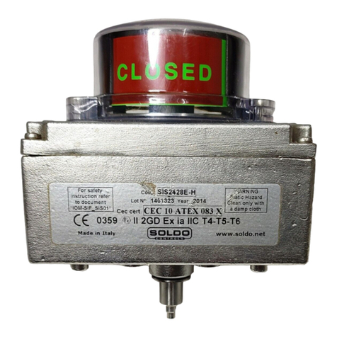
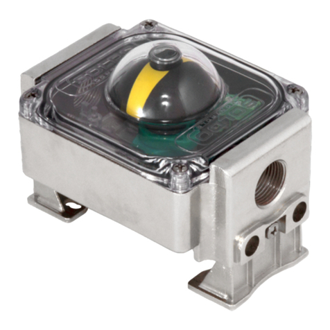
Soldo Controls SX Series User manual

LIMIT SWITCH BOXES
Series SX, SH
Indice dei contenuti - Table of Contents -
Pagg.
Page
Istruzioni di sicurezza
Safety instructions 1
Dichiarazione di conformità
Conformity declaration 2
Manuale di istallazione e uso
Installation & operating manual 3
Codifica opzioni
Nomenclature 5
Certificato di esame EC di tipo
EC type examination certificate 8
Soldo S.r.l.
Via Monte Baldo, 60
25015 Desenzano d/G (Brescia) Italy
Tel +39 030 999.13.09 FAX +39 030 914.19.77
http: //www.soldo.net e_mail: sales@soldo.net
Soldo reserves the right to change without notice

Soldo S.r.l.
Via Monte Baldo, 60
25015 Desenzano d/G (Brescia) Italy
Tel +39 030 999.13.09 FAX +39 030
914.19.77 http: //www.soldo.net –
e_mail: sales@soldo.net
Manuale di installazione e uso IOM-SX.SH00-01
Installation & Operation Manual IOM-SX.SH00-01
Document: SI001 Issued by: SB Date: 18/12/02
IT
Istruzioni di sicurezza per l’installazione in area pericolosa
Numeri di modello applicabili SX _ _ _ _ _-_ o SH _ _ _ _ _-_ ( _ identifica diverse opzioni di micro, quantità micro, morsetti, colore, ingressi
cavi).
Le istruzioni che seguono sono applicabili alle apparecchiature che posseggono la certificazione ATEX numero: 02ATEX 133733X
1. Il limit switch box serie SX può essere installato in area pericolosa con presenza di gas, vapori e polveri infiammabili gruppo IIB e con
classi di temperatura T4,T5,T6.
T6: -25°C ≤T amb. ≤+ 60° C
T5: -25°C ≤T amb. ≤+ 80° C
T4: -25°C ≤T amb. ≤+ 105° C
2. Il limit switch box serie SH può essere installato in area pericolosa con presenza di gas, vapori e polveri infiammabili gruppo IIB+ H2 e
con classi di temperatura T4,T5,T6.
T6: -25°C ≤T amb. ≤+ 60° C
T5: -25°C ≤T amb. ≤+ 80° C
T4: -25°C ≤T amb. ≤+ 105° C
3. L’installazione dovrà essere eseguita in accordo alle normative applicabili e da personale opportunamente addestrato.
4. Questa apparecchiatura non può essere riparata dall’utilizzatore.
5. Se sussiste la possibilità che l’apparecchiatura possa venire a contatto con sostanze aggressive, è responsabilità dell’utilizzatore
prendere le necessarie precauzioni per prevenire eventuali danni e assicurare che il grado di protezione non venga compromesso.
Sostanze aggressive - es. Acidi, liquidi o gas, che possono attaccare i metalli.
6. Si dovranno osservare le seguenti precauzioni:
iPotrebbero, in rarissime occasioni, verificarsi sorgenti potenziali di innesco dovute a scintille causate da urti o sfregamenti. Questo
deve essere tenuto in considerazione quando l’apparecchio è installato in area che richiede apparecchiature di gruppo II, categoria
2G.
ii A causa delle cariche elettriche elettrostatiche delle parti plastiche, il limit switch box, deve essere pulito solo usando un panno
umido.
GB
Safety instruction to hazardous area installation
Model numbers covered SX _ _ _ _ _-_ or SH _ _ _ _ _-_ ( _ indicates options in switches, switches quantity, terminal strip, colour, cable
entries).
The following instructions Apply to equipment covered by ATEX certificate number: 02ATEX 133733X
1. SX limit switch boxes may be used in an hazardous area with flammable gases, vapours and powder, group IIB with the following
temperature classes:
T6: -25°C ≤T amb. ≤+ 60° C
T5: -25°C ≤T amb. ≤+ 80° C
T4: -25°C ≤T amb. ≤+ 105° C
2. SH limit switch boxes may be used in an hazardous area with flammable gases, vapours and powder, group IIB+H2 with the following
temperature classes:
T6: -25°C ≤T amb. ≤+ 60° C
T5: -25°C ≤T amb. ≤+ 80° C
T4: -25°C ≤T amb. ≤+ 105° C
3. Suitably trained personnel shall carry out installation in accordance with applicable code of practice
4. The user should not repair this equipment.
5. If the equipment is likely to come into contact with aggressive substances, it is responsibility of the user to take suitable precautions that
prevent it from being adversely affected, thus ensuring that the type of protection is not compromised.
Agressive substances – es. Acidic liquids or gases that may attack metal .
6. The following precautions must be observed:
i The metallic alloy used for the enclosure, in the event of a rare accident, could cause ignition sources due to impact or friction
(sparks may occur). This shall be considered when the box is installed in group II category 2G areas.
ii Due to electrostatic charge of plastic pieces, the limit switch box shell only be cleaned with a damp cloth.
Page 1/10

Soldo S.r.l.
Via Monte Baldo, 60
25015 Desenzano d/G (Brescia) Italy
Tel +39 030 999.13.09 FAX +39 030
914.19.77 http: //www.soldo.net –
e_mail: sales@soldo.net
Manuale di installazione e uso IOM-SX.SH00-01
Installation & Operation Manual IOM-SX.SH00-01
Document: CE001 Issued by: SB Rev. 1 Date: 29/01/03
IT
GB
Dichiarazione di conformità ai sensi della direttiva
Atex 94/9/EC Declaration of conformity as defined by the ATEX
directive 94/9/EC
Dichiariamo, sotto la nostra responsabilità, che i SOLDO “limit switch
box SX series,
II 2 G/D EEx d IIB T6 to T4” e i SOLDO “limit
switch box SH series,
II 2G/D EEx d IIB+H2 T6 to T4” sono
conformi alle disposizioni delle direttive ATEX 94/9/EC “Equipment or
Protective Systems intended for use in potentially exlosive
atmospheres” e con l’adempimento della legislazione nazionale.
Inoltre dichiariamo che sono state applicate le norme:
EN 50014
EN 50018
EC- Certificato di controllo Tipico
02ATEX 133733X
Notifica della assicurazione qualità
Ul Demko Q135510
Herewith we declare that the SOLDO “limit switch box SX series,
II 2G/D EEx d IIB T6 to T4” and the SOLDO “limit switch box SH
series,
II 2G/D EEx d IIB T6 to T4” are in conformity with the
provision of the ATEX directive 94/9/EC “Equipment or Protective
Systems intended for use in potentially explosive atmospheres” and
with national implementing legislation and that appropriate harmonized
standards have been applied:
EN 50014
EN 50018
EC- Type examination certificate
02ATEX 133733X
Production quality assurance notification:
Ul Demko Q135510
FR
DE
Déclaration of conformity as defined by Atex
directive 94/9/EC Konformitätserklärung im Sinne der ATEX richtlinie
94/9/EC
Par la présente nous déclarons que les SOLDO“limit switch box SX
series,
II 2 G/D EEx d IIB T6 to T4” et les SOLDO “limit switch
box SH series,
II 2G/D EEx d IIB+H2 T6 to T4” sont conformes
aux dispositions des Directive ATEX 94/9/EC “Equipment or
Protective Systems intended for use in potentially exlosive
atmospheres” et aux législations nationales les transposant.
Les normes applicables sont:
EN 50014
EN 50018
Attestation d’examen CE de type:
02ATEX 133733X
Assurance qualité de production:
Ul Demko Q135510
Hiermit erklären wir, dass die SOLDO “limit switch box SX series,
II 2G/D EEx d IIB T6 to T4” und SOLDO “limit switch box SH series,
II 2G/D EEx d IIB T6 to T4” den ATEX 94/9/EC “Equipment or
Protective Systems intended for use in potentially exlosive
atmospheres” sowie den einschlägigen nationalen
Durchführungsbestimmungen entsprechen.
Folgende normen wurden zugrundegelegt:
EN 50014
EN 50018
EG- Baumusterprüfbescheinigung:
02ATEX 133733X
Anerkennung Qualitätssicherung der Produktion:
Ul Demko Q135510
Page 2/10

Soldo S.r.l.
Via Monte Baldo, 60
25015 Desenzano d/G (Brescia) Italy
Tel +39 030 999.13.09 FAX +39 030
914.19.77 http: //www.soldo.net –
e_mail: sales@soldo.net
Manuale di installazione e uso IOM-SX.SH00-02
Installation & Operation Manual IOM-SX.SH00-02
READ THIS INSTRUCTION FIRST
To avoid serious or fatal personal injury or major property
damage, read and follow all safety instruction in this manual.
If you require additional assistance, please contact the
manufacturer. SAVE THIS INSTRUCTION
SAFETY ALERT SYMBOLS
DANGER Warns of hazard that WILL cause serious personal
injury, death or major property damage.
WARNING Warns of hazard that MAY cause serious personal
injury, death or major property damage.
CAUTION Warns of hazard that MAY cause personal injury or
property damage.
DANGER
Follow SI001 (page 1) for safety instruction to hazardous area
installation. WARNING
HAZARDOUS VOLTAGE Due to the risk of electric shock
disconnect all power before servicing equipment.
CAUTION
Do not exceed the limit switch performance limitation. Exceeding
the limitation may cause damage to the limit switch.
Limit switchbox for quarter-turn valve device (90° rotation).
Maximum shaft angular velocity 250 rpm. Not comply with this note
cause damage.
1e INSTALLATION
1.1 Attach proper mounting bracket (1) to the box housing (4) using
four M 6x8 bolts (2).
1.2 Align shaft (5) to actuator shaft and engage it.
1.3 Attach bracket (1) to actuator using hardware provided (3).
2e SWITCH ADJUSTMENT
2.1 Loose the screws (8) and remove box cover (7).
2.2 Follows indication in “Cams setting – Regolazione delle Camme”
(page 7)
2.3 Box with 4 switches, set the actuator in the two extra position
you have to signal. Act according to indications in “Cams setting –
Regolazione delle Camme” to set cams of the switch number 3 and
4.
2.4 Replace Switch box aluminium cover (7). WARNINGS: check
seal (6) is properly fitted in slot. Turn manually cover’s shaft (15)
cheeking to align it to switch box shaft and engage it.
2.5 Tighten screws (8) to fix limit switch box cover (7).
3e 3D INDICATOR SETTING
3.1 Remove four screws (13) and remove 3D indicator’s cover (12).
3.2 Remove screw (10) and lift up 3D indicator (9) from its splined
retainer.
3.3 Set 3D indicator (9) on splined retainer according to valve
position.
3.4 Fix 3D indicator screwing the (10) screw.
3.5 Replace cover of 3D indicator (12). WARNINGS: check seal (11)
is properly fitted in slot.
3.6 Tighten screws (13) to fix 3D indicator cover (12).
4e ELECTRICAL WIRING
4.1 Remove cover according point 2.1.
4.2 Remove protection plugs from cable entries and substitute them
with cable glands or plugs suitable for type of protection required.
4.3 Connect terminal strip (14) according to the wiring diagram in
“Cams setting – Regolazione delle Camme”
4.4 Reassemble cover (7) according to points 2.4 and 2.5.
PRIMA DI INSTALLARE IL BOX LEGGERE QUESTE ISTRUZIONI
Per evitare il ferimento, la morte o danni importanti a oggetti
leggere e seguire tutte le istruzioni di sicurezza presenti in
questo manuale. Se vi servono informazioni aggiuntive non
esitate a contattate il produttore .
CONSERVATE QUESTE ISTRUZIONI
SIMBOLI DI SEGNALAZIONE PERICOLO
DANGER Segnalazione di pericolo che non rispettata causerà serie
ferite, morte o danni importanti a oggetti.
WARNING Segnalazione di pericolo che non rispettata potrà
causare serie ferite, morte o danni importanti a oggetti.
CAUTION Segnalazione di pericolo che non rispettata potrà
causare ferite o danni a oggetti.
DANGER
Seguire le indicazioni del documento SI001 (Page 1) per
l’installazione in area pericolosa.
WARNING
PERICOLO SCOSSE ELETTRICHE. Togliere l’alimentazione elettrica
prima di collegare o manutenere l’apparecchio.
CAUTION
Non superare le limitazioni di utilizzo degli switch. Il superamento
delle limitazioni può causare il danneggiamento degli switch.
Limit switch box per uso su valvole a quarto di giro (90°). Massima
velocità di rotazione dello stelo 250 rpm. Non rispettando questa
indicazione si producono danni.
1i INSTALLAZIONE SULL’ATTUATORE
1.1 Fissare la staffa (1) al corpo del box (4) utilizzando le 4 viti a cava
esagonale M 6x8 (2).
1.2 Ruotare manualmente lo stelo (5) in modo che il lembo fresato sia
parallelo alla cava situata sul pignone dell’attuatore, quindi innestarlo
alla stessa.
1.3 Fissare la staffa (1) all’attuatore con le viti fornite a corredo (3).
2i REGOLAZIONE DEI FINECORSA
2.1 Svitare le quattro viti (8) per rimuovere il coperchio del box (7).
2.2 Seguire le indicazioni della tabella “Cams setting – Regolazione
delle Camme” (page 7).
2.3 Se box con 4 micro, portare l’attuatore nelle altre due posizione in
cui si desiderano le segnalazioni. Regolare le due camme per i micro
3 e 4 agendo come da indicazioni della tabella “Cams setting –
Regolazione delle Camme” .
2.4 Rimontare il coperchio in alluminio (7) sul box (4) curando che la
guarnizione (6) sia correttamente posta nella sua cava nel coperchio.
Per effettuare questa operazione ruotare manualmente lo stelo (15)
del coperchio in modo che il lembo fresato sia parallelo alla cava
situata sul stelo del box, quindi innestarlo allo stesso.
2.5 Serrare le viti (8) per fissare il coperchio del box (7).
3i REGOLAZIONE INDICATORE 3D
3.1 Svitare le quattro viti (13) e sollevare il coperchio dell’indicatore
3D (12).
3.2 Svitare la vite (10) e tirando verso l’alto sfilare l’indicatore 3D (9)
dal suo supporto millerighe.
3.3 Innestare l’indicatore 3D (9) sul millerighe curando che la sua
posizione rispecchi la posizione della valvola.
3.4 Fissare l’indicatore avvitando la vite (10).
3.5 Rimontare il coperchio dell’indicatore 3D (12) curando che la
guarnizione (11) sia correttamente alloggiata nella sua cava.
3.6 Avvitare le viti di fissaggio (13) del coperchio dell’ indicatore 3D
(12).
4i CABLAGGIO ELETTRICO
4.1 Rimuovere il coperchio (7) come indicato nei punti 2.1.
4.2 Rimuovere i tappi di protezione e sostituirli con pressacavo/i ed/o
tappo/i filettati, che garantiscano il livello di protezione richiesto.
4.3 Collegare i morsetti (14) seguendo lo schema elettrico indicato in
tabella “Cams setting – Regolazione delle Camme” .
4.4 Rimontare il coperchio (7) come da indicazioni 2.4 e 2.5.
Page. 3/10

Soldo S.r.l.
Via Monte Baldo, 60
25015 Desenzano d/G (Brescia) Italy
Tel +39 030 999.13.09 FAX +39 030
914.19.77 http: //www.soldo.net –
e_mail: sales@soldo.net
Manuale di installazione e uso IOM-SX.SH00-02
Installation & Operation Manual IOM-SX.SH00-02
Pa
g
e 4/10

Soldo S.r.l.
Via Monte Baldo, 60
25015 Desenzano d/G (Brescia) Italy
Tel +39 030 999.13.09 FAX +39 030
914.19.77 http: //www.soldo.net –
e_mail: sales@soldo.net
Manuale di installazione e uso IOM-SX.SH00-02
Installation & Operation Manual IOM-SX.SH00-02
NOMENCLATURE CODIFICA OPZIONI
01 2 0 0 - 1
SX
SH cable entry
1 n°2 ½” npt
2 n°2 M20x1.5
3 n°2 ½” npt +n°1 ¾” npt
4 n°2 M20 x 1.5 +n°1 M25 x 1.5
colour
0 black
1 blue RAL 5015
terminal strip
0 standard PCB + extra solenoid terminals
2
7
8
blue PCB + extra solenoid terminals
cage clamp blue + extra poles for solenoid valve
cage clamp blue
switch quantity
1 to 4 according switch type
switch type rating
Voltage Min Max resistive load Max inductive load
max qty
installed
01 electromech SPDT silver
plated contacts
250 Vac
110Vac
24 Vdc
50 mA
50 mA
50mA
5A
5A
3A
5A (power factor 0.4, time costant 7 ms)
5A
3A temp. range -20°C +80°C
4 SX
2 SH
02 electromech SPDT gold
plated contact
hermetically sealed
250 Vac
110Vac
24 Vdc
5 mA
5 mA
1 mA
3A
3A
1A
1.8A (power factor 0.4, time costant 7 ms)
2A
12A temp. range -20°C +80°C
4 SX
2 SH
03 electromech SPDT gold
plated contacts
250 Vac
110Vac
24 Vdc
5 mA
5 mA
1 mA
3A
3A
1A
1.8A (power factor 0.4, time costant 7 ms)
2A
12A temp. range -20°C +80°C
4 SX
2 SH
07 electromech SPDT gold
plated contacts inert gas
hermetically sealed
250 Vac
110Vac
28 Vdc
--
5 mA
1 mA
--
3A
5A inductive/ resistive load temp. range -20°C +80°C
4 SX
2 SH
C4 proximity SPDT inert gas
hermetically sealed
240 Vac
110Vac
24 Vdc
--
--
--
-- Only resistive load (cos ∅=1)
1A
1A Max 25 W temp. range -20°C +80°C
4 SX
2 SH
17 electromech SPDT gold
plated contacts
hermetically sealed (ip67)
250 Vac
110Vac
24 Vdc
5 mA
5 mA
1 mA
0.1A
0.1A
0.1 A
50 mA (power factor 0.4, time costant 7 ms)
60 mA
70 mA temp. range -20°C +80°C
4SX
0SH
One cam operates two switches
18 electromech SPDT silver
plated contacts
hermetically sealed (ip67)
250 Vac
110Vac
24 Vdc
50 mA
50 mA
50 mA
2 A
2 A
2 A
1 mA (power factor 0.4, time costant 7 ms)
1.2 mA
1.6 mA temp. range -20°C +80°C
4SX
0SH
One cam operates two switches
20 proximity
NAMUR
P+F
NJ4 12GK N
Nom. voltage
U
0
= 8Vdc
sensibility 4 mm, current consumption :1mA (face covered), 3mA (face not
covered), self inductance 50 µH, self capacitance: 45 nF
temp. range -20°C +80°C
2 SX
2 SH
22 proximity PNP NO P+F
NBB2 12GM50 E2
Oper. voltage:
10-30 Vdc
sensibility 2 mm, operating current : 200 mA, voltage drop: 3V, min.
consumption : 17 mA, led indicator temp. range -20°C +70°C 2 SX
0 SH
23 proximity PNP NO P+F
NBN4 12GM50 E2
Oper. voltage:
10-30 Vdc
sensibility 4 mm, operating current : 200 mA, voltage drop: 3V, min.
consumption : 17 mA, led indicator temp. range -20°C +70°C
2 SX
0 SH
24 proximity
NAMUR
P+F
NJ2 12GK N
Nom. voltage
U
0
= 8Vdc
sensibility 2 mm, current consumption :1mA (face covered), 3mA (face not
covered), self inductance 50 µH, self capac.: 45 nF temp. range -20°C +80°C
2 SX
2 SH
28 proximity
NAMUR
P+F
NJ2 11 N G
Nom. voltage
U
0
= 8Vdc
sensibility 2 mm, current consumption :1mA (face covered), 3mA (face not
covered), self inductance 50 µH, self capac.: 30 nF temp. range -20°C +80°C 2 SX
0 SH
32 proximity NO P+F
NBN4 12GM40 Z0
Oper. voltage:
10-60 Vdc
sensibility 4 mm, operating current : 4-100 mA, voltage drop: 6V, off-state
current : 0.7 mA, led indicator temp. range -20°C +80°C
2 SX
0 SH
36 proximity
NAMUR
P+F
NJ5-11-N-G
Nom. voltage
U
0
= 8Vdc
sensibility 2 mm, current consumption :1mA (face covered), 3mA (face not
covered), self inductance 50 µH, self capac.: 30 nF temp. range -20°C +80°C 2 SX
0 SH
39 proximity
NAMUR
P + F NJ2 12GK SN
Nom. voltage
U
0
= 8Vdc
sensibility 2 mm, current consumption :1mA (face covered), 3mA (face not
covered), self inductance 150µH, self capac.: 50nF temp. range -20°C +80°C 2 SX
0 SH
60 proximity
NAMUR
P+F
SJ 3.5 N
Nom. voltage
U
0
= 8Vdc
sensibility 4 mm, current consumption :1mA (face covered), 3mA (face not
covered), self inductance 100µH, self capac.: 30nF temp. range -20°C +80°C 2 SX
0 SH
62 proximity
NAMUR
P+F
SJ 3.5 SN
Nom. voltage
U
0
= 8Vdc
sensibility 4 mm, current consumption :1mA (face covered), 3mA (face not
covered), self inductance 100µH, self capac.: 30nF temp. range -20°C +80°C
2 SX
0 SH
70 proximity
NAMUR
P+F
NJ2 V3 N
Nom. voltage
U
0
= 8Vdc
sensibility 2 mm, current consumption :1mA (face covered), 3mA (face not
cover) self inductance 50 µH self capac.: 40 nF temp. range -20°C +80°C
4 SX
2 SH
73 proximity PNP NO P+F
NBB2 V3 E2
Oper. voltage:
10-30 VDC
PNP NO 3 wire amplified, sensibility 2 mm Operating current : max 100 mA
Voltage drop: 3V min. consumption : 15 mA temp. range -20°C +70°C 4 SX
2 SH
75 proximity IFM 5026
NC / NO programmable
Oper. voltage:
5-36 Vdc
sensibility 2 mm, operating current : 4-200 mA, voltage drop: 4.6V, leakage
current : 0.8 mA. temp. range -20°C +80°C 4 SX
2 SH
Page 5/10

Soldo S.r.l.
Via Monte Baldo, 60
25015 Desenzano d/G (Brescia) Italy
Tel +39 030 999.13.09 FAX +39 030
914.19.77 http: //www.soldo.net –
e_mail: sales@soldo.net
Manuale di installazione e uso IOM-SX.SH00-02
Installation & Operation Manual IOM-SX.SH00-02
4
EXTRA
POLES
(optional)
EXTRA
POLES
EXTRA
POLES
EXTRA
POLES
EXTRA
POLES
EXTRA
POLES
EXTRA
POLES
(optional)
Spostare la camma fino a disinnestrarla dal millerighe.
Disingage cam from splined retrainer.
Spostare la camma fino a disinnestrarla dal millerighe.
Disingage cam from splined retrainer.
Ruotarla, nella direzione indicata, fino a che fino all'azionamento dell'interruttore, poi reinserirla nel mille righe.
Turn, in the way shown, until switch is activated, then engage into splined retrainer.
Allentare (chiave del 19) il dado superiore
Ruotare la camma per portarla di fronte al sensore
Loosen (using a 19 wrench) top nut
Rotate cam and fit in front of sensor
Serrare (chiave del 19) il dado superiore
Fasten (using a 19 wrench) top shaft nut
Ruotare la camma indicata
per portarla di fronte al sensore
Rotate cam (shown in drawing)
and fit in front of sensor
Ruotare la camma indicata
per portarla di fronte al sensore
Rotate cam (shown in drawing)
and fit in front of sensor
56
Serrare (chiave del 19) il dado superiore
Fasten (using a 19 wrench) top shaft nut
Allentare (chiave del 19) il dado superiore
Ruotare la camma per portarla di fronte al sensore
Loosen (using a 19 wrench) top nut
Rotate cam and fit in front of sensor
2-3
Far ruotare il pignone dell'attuatore in senso antiorario
Turn actuator pinion counter clockwise
Far ruotare il pignone dell'attuatore in senso orario
Turn actuator pinion clockwise
2
1
5
63
2-3 56
Wiring diagram
Model Regolazione delle camme - Cams setting
S*0120X-X
S*0220X-X
S*0320X-X
S*0720X-X
S*C420X-X
S*2028(7)X-X
S*2428(7)X-X
S*2828(7)X-X
S*3628(7)X-X
S*3928(7)X-X
S*7022X-X
S*7320X-X
S*7520X-X
S*2220X-X
S*2320X-X
S*3220X-X
S*6028(7)X-X
S*6228(7)X-X
Page 6/10

Soldo S.r.l.
Via Monte Baldo, 60
25015 Desenzano d/G (Brescia) Italy
Tel +39 030 999.13.09 FAX +39 030
914.19.77 http: //www.soldo.net –
e_mail: sales@soldo.net
Manuale di installazione e uso IOM-SX.SH00-02
Installation & Operation Manual IOM-SX.SH00-02
S*0140X-X
S*0240X-X
S*0340X-X
S*C440X-X
S*0740X-X
S*C430X-X
S*C440X-X See previous
wiring diagram
S*013 = S*C43
S*014 = S*C44
S*1740X-X
S*1840X-X
Switch position
Model
S*0130X-X
S*0230X-X
S*0330X-X
S*C430X-X
S*0730X-X
Wiring diagram
Page 7/10


Other manuals for SX Series
1
This manual suits for next models
1
Table of contents
Other Soldo Controls Switch manuals