Solenso DTU SLT User manual
DTU SLT User Manual

© 2023 Solenso electronic materials Co.,LTD. All rights reserved.
About the Manual
This manual contains important instructions for the SLT and must be read in its entirety before installing or
commissioning the equipment. For safety, only qualified technician, who has received training or has
demonstrated skills can install and maintain this SLT under the guide of this document.
Other Information
Product information is subject to change without notice. User manual will be updated frequently, please
refer to Solenso official website at https://www.solenso-global.com/ for the latest version.

© 2023 Solenso electronic materials Co.,LTD. All rights reserved.
Table of Contents
1. Terminals Introduction.................................................................................................................... 1
2. Introduction to product software functions ............................................................................. 4
3. Installation ..........................................................................................................................................9
4.Technical parameters ...................................................................................................................... 10

© 2023 Solenso electronic materials Co.,LTD. All rights reserved.`
1
1. Terminals Introduction
1.1 About SLT
①:LED1,SLT working condition light;
②:LED2,SLT communicate with the platform indicator light;
③:LED3,SLT communicate with the microinverter indicator light;
④:Reset Button;
⑤:DC 5V Input Port;
⑥:RS485 Port;
⑦:Ethernet Port;
⑧:DRM Port;
⑨:AP Button.
Specific functions of each port see Section 1.3 and Section 1.5.
1.2 Communication mode
Adopt the 2.4G wireless scheme with the SLT communication; Adopt the network cable and Wi-Fi
coexistence scheme for the communication with the monitoring platform.

© 2023 Solenso electronic materials Co.,LTD. All rights reserved.`
2
1.3 Peripheral interface
The peripheral interface includes RS485 interface, DRM, LED indicator light, Reset button and AP button.
The functions of each interface are briefly described as follows:
RS485:This interface has two functions, one is to prevent reverse flow, the other is to meet the needs of
remote scheduling in Europe (Integrated Sunspec Modbus protocol).
DRM:Meet the DRM power dispatch requirements and this function only for Australia.
LED:There are three LED indicators that represent the SLT and platform communication, SLT and
microinverter communication, and SLT working status.
Reset:Resets the associated network configuration for the communication with the platform.
AP:This button is used to switch between AP and STA modes.
When DTU use WiFi router communicate to Solenso cloud please use AP mode, when use DTU use a 4G
SIM card communicate to Solenso cloud please use STA mode.
RTC:After the power outage, power up within 7 days, keep the time.For example after DTU lost grid
power,if DTU reconnect to grid within 7 days, the time setting will be keep and no need to set. If DTU reconnect
to grid over 7 days the time of DTU need to reset.
1.4 Power supply mode
This product uses 5V power supply, external power supply adapter。
1.5 Indicator light description
This product has 3 LED indicators, respectively representing the SLT status indication, SLT and platform
communication, SLT and microinverter communication, as described in the table below。

© 2023 Solenso electronic materials Co.,LTD. All rights reserved.`
3
Start / firmware upgrade
The three-lights flash every 0.5 seconds
Machine start
The three-lights flash every 1 second
Firmware update
Three lights flashing at the same time, 0.2 seconds on,
0.8 seconds out
Reset success
SLT Status indicator light (green)
Often bright
Electrify
Light flash 0.5s+0.5s
SLT Work failure
Often destroyed
Unelectrified
SLT and platform communication (green)
Often bright
The connection platform is normal
Light flash 0.5s+0.5s
Wait for / try to connect to the network
Light flash slowly1s+1s
Not connected to the monitoring platform
Light flash 0.5s +1.5s
AP mode
SLT and microinverter communication (green)
Often bright
Communication is normal
Light flash 0.5s+0.5s
There are microinverter not on the communication
Light flash1s+1s
All microinverter are not communicated on
Light flash1.5s
SLT unconfigured microinverter ID
© 2023 Solenso electronic materials Co.,LTD. All rights reserved.`
4
2. Introduction to product software functions
2.1 Network configuration
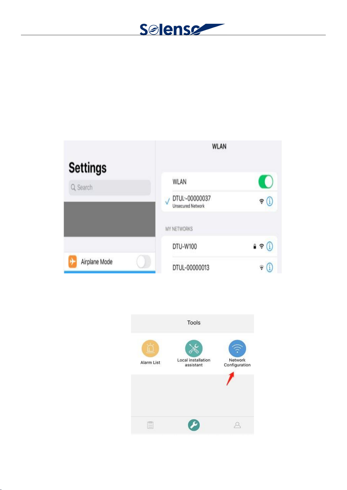
1、Use the smart phone or tablet to connect the DTU built-in WIFI“DTUL-XXXXXXXX”(XXXXXXXX is the
last eight number of DTU serial number) .
2、Use the mobile phone to open the installer APP Sofia Pro and log in. Enter the "Operation and
Maintenance Center" at the bottom of the page.

© 2023 Solenso electronic materials Co.,LTD. All rights reserved.`
5
3、 Click ''Wi-Fi'' and input the WIFI name and password of the client , ensure this WIFI can access the
Internet. Then click ''Send to DTU'' .
4、Waiting for the ''Connection Succeeded'' tips which means DTU has connect to the server.
5、If the network cable is used, the network cable side is connected to the router LAN port, and the other
side connects to the SLT network port. Use the mobile phone to open the installation terminal APP and log in,
enter the "Operation and Maintenance Center" at the bottom of the page, and then enter the "Network
Configuration", and select "Ethernet"

© 2023 Solenso electronic materials Co.,LTD. All rights reserved.`
6
6、Click on“Send to DTU" and waiting for the "Connection Succeeded" tips.
2.2 Microinverter data and information upload
At the data level, the data is uploaded in units of micro-inverse.
1、Network disconnection storage data for a week;

© 2023 Solenso electronic materials Co.,LTD. All rights reserved.`
7
2、Upload time interval is standard with 15 minutes. In addition, the RS485 port only supports
anti-counterflow, Sunspec Modbus protocol functions.
2.3 Monitoring system
1、Login
1)Apply for account number
For distributors, you can contact the Solenso team to create an account;
For installers, you can contact the distributors to create an account;
For individuals, you can contact the installer to create an account.
2)System requirements
Browser: Recommend Google Browser;
Screen resolution: Recommended 1920 * 1080, support 1366 * 768.
3)Login address
https://monitor.solenso.net/platform/home
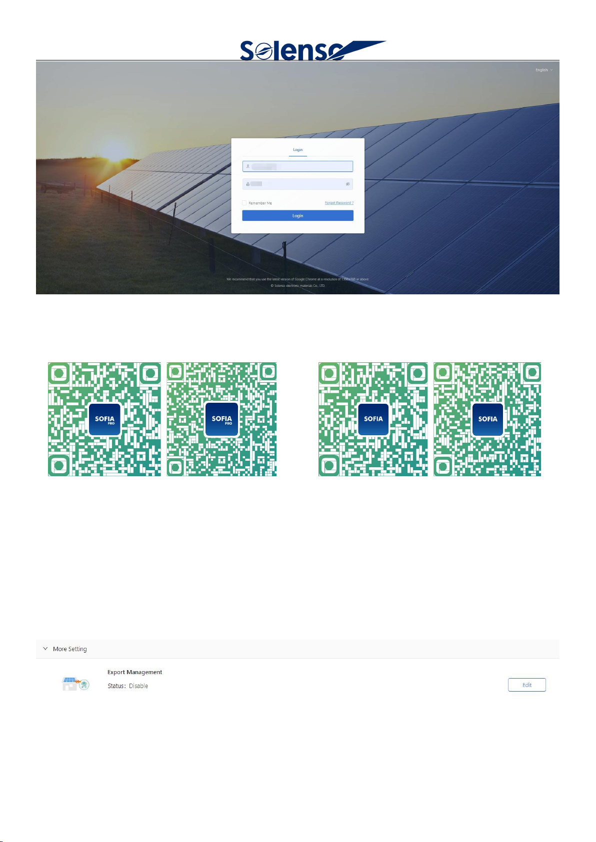
4)Login interface
© 2023 Solenso electronic materials Co.,LTD. All rights reserved.`
8
5)Download APP
Installer APP Sofia Pro Installer APP Sofia
IOS Android IOS Android
6、setting
1)Zero export setting
Select Enable Export Management, if open the Anti-counter current, select power grid mode, select
electricity meter position.
2)Power station setting

© 2023 Solenso electronic materials Co.,LTD. All rights reserved.`
9
Monetary unit and electricity price setting, advanced setting, network setting.
2.4 Anti-current function
1、Only support the new three kinds Chint electricity meters: DDSU666 100A, DTSU666 100A, DTSU666
250A, only support the grid side, address default 001;
2、Only support the general control mode, can not be carried electrical separation;
3、It can support the three-phase 230 / 400, crack phase 120 / 240, and crack phase 120 / 208 power grid.
3. Installation
1. When installing a SLT with a wall-mounted bracket, select a cool, dry indoor position, fit the wall
installed by the SLT, using two gypsum board screws or wall anchors, align and slide the SLT to the mounting
screw.
© 2023 Solenso electronic materials Co.,LTD. All rights reserved.`
10
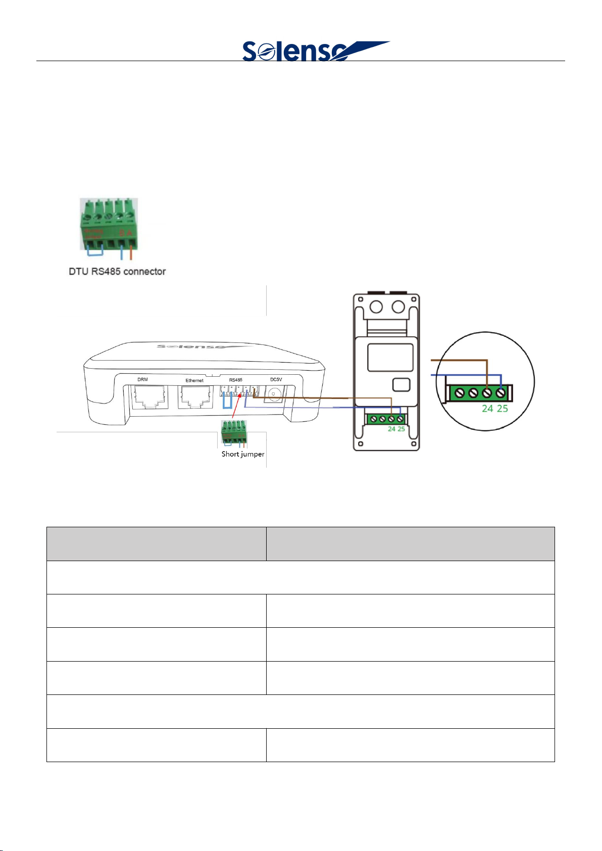
2 . There is a green RS485 cable connector, please lock the RS485 cable and shorting jumper cable
( optional ) to the green RS485 connector with screwdriver.
3 . Insert the RS485 connector to DTU RS485 port.
4 .The picture below indicates the RS485 A Port and B Port on SLT.
4.Technical parameters
Model
SLT
Communication to Microinverter1
Type
Wireless_2.4G
Maximum distance (open space)
200m
Max. number of connected microinverter
25
Communication to Cloud
Signal
Wi-Fi(802.11b/g/n)2/Ethernet

© 2023 Solenso electronic materials Co.,LTD. All rights reserved.`
11
Sample rate
Per 15 minutes
Communication to Meter
Signal
RS485
Maximum distance (RS485 cable)
500m
Interaction
LED
LED Indicator * 3
APP
Local APP
Power Supply (Adapter)
Type
External adapter
Adapter input voltage/frequency
100 to 240 V AC / 50 or 60Hz
Adapter output voltage/current
5V / 2A
Power consumption
2.5W (typical), 5W (maximum)
Mechanical Data
Ambient temperature (℃)
-20°C to 50°C
Dimensions(W×H×D mm)
114×87×28.5
Weight
0.20 kg
Installation options
Wall mounting / Desktop mounting
Features
Compliance
CE
*1 Depending on the installation environment, please refer to user manual for more details.

© 2023 Solenso electronic materials Co.,LTD. All rights reserved.`
12
*2 If the SLT installation location is inside the metal box or under the metal/concrete roof, extended
antenna will be suggested.
Table of contents
Popular Network Hardware manuals by other brands

Acnodes
Acnodes KD 6176 user manual

Swissvoice
Swissvoice Voice Bridge Quick user guide

Rutenbeck
Rutenbeck PPR 6 operating instructions

uniview technologies
uniview technologies Network Video Recorders quick guide

Riverbed
Riverbed Steelhead CX Series installation guide

PRECISION DIGITAL
PRECISION DIGITAL PDW30 instruction manual

WebGate
WebGate WebEye B106 Quick reference guide

National Instruments
National Instruments R Series Getting started guide

Genexis
Genexis FiberTwist Series installation guide

ADTRAN
ADTRAN 6540 Installation and maintenance guide

Artic
Artic AR-DB16F installation manual

National Instruments
National Instruments Fieldpoint cFP-RTD-124 operating instructions


