Soletric RC51141 User manual

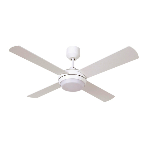
Eco-Breeze Solar Powered Ceiling Fan
INSTALLATION GUIDE
RC51141
Please read entire guide before starting installation
Safety Information:
•The most dangerous aspect of installing your Solectric™ Eco-Breeze Ceiling Fan is climbing up onto your
roof. If you have no skill or knowledge of what safety precautions are necessary when working on your
roof, please do not attempt it; contact a local roofing contractor to assist you.
•The Solectric™ Eco-Breeze Ceiling Fan works on low voltage DC (less than 24 Volts). Under no
circumstances should you try to connect any wires from this system directly to your household electrical
system (120/240 VAC).
•Please check with your local building department about permit requirements.
•Roof leaks could occur if not installed properly. Please use a qualified roofing contractor if you have no
experience in this area.
•When working in attic area, please be careful to step only on wooden rafters and joists and not directly on
the insulation or drywall as you could damage the ceiling and possibly fall through. Wear a dust mask,
goggles and full body covering to minimize insulation irritation. Avoid middle of the day high heat.
IMPORTANT!! Do not connect the wires from the solar panel until all other installation
work is complete. Cover solar panel with a dark towel when making final connection.
Location of Solar Panel:
•Mount as high on the roof as practical; this will minimize shading issues and the potential for roof leaks.
See Figure 1.
•Locate on a south facing area of roof. Since this is not always practical, you can position anywhere between
South East and due West. A more eastern direction will give you more morning light while a south western
direction will favor afternoon light.
•Avoid shading. Even a small amount of shade can disproportionately reduce the power output of your
Solectric™ Eco-Breeze Ceiling Fan System.
•Mount near an existing vent for easy wire access to the attic. Ridge vents and eyebrow vents are the first
choice. Air exhaust vents (from kitchen and bath fans) can also be used but be careful not to run wires
through fan areas. If no vent access is available, a small hole can be drilled as described in Step # 2.
•It is not advised to run any wires directly down a sewer vent. If that is the closest vent, you could run the
wire on the outside of the pipe, through the rubber gasket. Apply roofing sealant as needed.

•Keep in mind the location of the lights to try to minimize total wire length.
Please note: These instructions are for installation on roofs with composition shingles over
plywood sheeting. If you are not aware of what type of roof you have please contact a
roofing expert for assistance. We have not yet developed kits for roof types other than
composition shingle, but will do so in the near future. Until then please refer to the end of
this guide. Check our website; www.renconenergy.com for helpful hints on dealing with
various different roof types. If you have found a better way to mount the panels please let us
know by using the “contact us” feature.
Step 1: Decide where you want the lights to be mounted, then follow the assemble instructions for the Ceiling
Fan and mount it.
Step 2: (optional) If no suitable vent or attic access is available near to where you would like the solar panel
mounted, you can drill a small 1/4” diameter hole in your roof as described. Carefully peel back a corner of a
ridge shingle as shown in Fig. 2 using a flat pry bar and your fingers. Be careful not to crack the shingle. If
your roof is old use extra caution and do not peel back as far as the figure shows. Drill a 1/4” diameter hole as
far under the ridge shingle as practical. Seal the hole in Step 6.
Step 3: From inside the attic, locate the light fixture position closest to where the solar panel will be mounted
and pull back the ceiling insulation. Prepare wire for installation by cutting back the outer jacket approximately
2” and then removing the insulation from the individual red and black wires, a distance of 3/8”. Insert the
prepared end of wire into the pre-drilled hole so that it protrudes approximately 3” into living space. Run wire
over to the next light fixture position and cut to a length that allows the same 3” protrusion. Prepare cut end as
before. Estimate the length of wire needed to go from the first light fixture position to the solar panel, to see if
the remaining length of wire is enough. If not, please order additional wire through our web site. Otherwise,
you can purchase wire some from your local building supply store. It must be 2 conductor, 16 GA or lower
number GA, copper wire with an additional outer sheath like the type provided. If that is not available, wire
intended for low voltage outdoor lighting is acceptable. Run the other end of the wire out from the attic through
an existing vent, rubber collar or hole produced in Step 2. See Step 5 for sealing instruction.
Step 4: Connect the wires to the Ceiling Fan. Match red wire from fixture with the one or two red wires
coming through the ceiling; secure with wire nut. Repeat for black wires.
Step 5: Remove solar panel from its box. CAUTION: Keep panel face down while performing this critical
step. Remove the insulation from the end of the red wire and replace it with a wire nut and tighten. Repeat
with the black wire. Never remove the wire nuts unless the panel is face down or a dark towel covers the panel.
Install 4 brackets onto the solar panel as shown in Figure 3, using 4 per solar panel of the #8-32 screws, inserted
first into the bracket then into the solar panel. Then install a washer and nylon locking nut from under the
flange of the solar panel. Tighten while keeping the brackets perpendicular to the edge of the solar panel. One
of the bracket holes will need to be drilled out to a 1/8” diameter or larger to accommodate a tie wrap. See
Figure 3. do not attach wires or tie wrap yet). Protect the solar panel by placing a small scrap of wood between
the bracket and the back of the solar panel while drilling.

Step 6: Using great care, take panel/bracket assembly and an old towel up on the roof and set panel upside
down on towel near the desired location. If you ran the wire through a drilled hole per Step 2, now is the time
to seal it up with a roofing cement or sealant around the hole and under the raised shingle. Press the shingle
into the sealant and temporarily hold it down with duct tape or a heavy weight. If wire was passed through an
existing vent pipe rubber gasket, seal that now. For a normal “temporary” installation, apply a small (dime
sized) glob of roofing sealant to the 4 holes as shown in Figure 3. Turn the assembly over and place in the
desired position. Be careful not to have any of the brackets span two shingles as shown in Figure 2. Using the
1-1/2” long black self-tapping screws provided, drive screw through sealant, bracket and underling shingle into
plywood sheeting. Be careful not to over-tighten screws. Cover the solar panel with the towel. After covering,
attach wires to solar panel, one at a time, red to red, black to black. Fully tighten the wire nuts. Remove towel
and check if lights are on. If the lights are not working and there is good sun on the panel then cover again with
towel and ensure the wire color pairing is correct at the panel and at the fixtures (Red to Red and Black to
Black). Remove towel and re-check. If still not working replace towel, switch polarity back and then check
connections at light fixtures. Once everything works properly, apply dab of roofing sealant to base of wire nut
to prevent moisture intrusion. Tie wrap connections to underside of solar panel, close to junction box. See
Figure 3.
Option A: Follow this step: If you would like the option of running your Solectric™ Eco-Breeze Ceiling Fan
when no solar power is available. From a hardware store obtain a regular AC light switch, a remodel box, cover
plate and 16 GA, 2 wire cable. Locate switch on an interior wall, as close to fixture as possible, in between
studs where there is currently no switches located .This is important so there is never a chance of accidentally
wiring into the existing 120 VAC system. Use template provided with remodel box to cut a hole in drywall
where you want the switch. From the attic, drill a 3/8” hole into the center of the wall directly above cut-out.
Using fish tape and a friend, run wire from attic to the switch opening. Install box with wire running through it.
Attach one wire to one side of the switch and other wire to the other side, then install switch into box. See
Figure 7. Finish up with faceplate. Bring the other end of wire through ceiling hole and install one side to the
red fixture wire and the other side to the red wire(s) coming from the solar panel. Install fixture as described
above and test.
ADDITIONAL ITEMS NEEDED FOR INSTALLATION
Roof Sealing Compound
Additional Wire
If you have any questions please contact:
RenCon Energy Products, Inc.
472 Moore Lane
Healdsburg, CA 95448
(800) 601-0692
www.renconenergy.com

Wiring Diagram
Table of contents
