SOLID AIR FDC2 User manual

1| Round re damper manual 02/2021
SOLID AIR
®
CLIMATE SOLUTIONS • T +31 598 36 12 21 • www.solid-air.com •mail@solid-air.com
TECHNICAL MANUAL
Round re damper
FDC25 |FDC40
INDEX
1. PRODUCT OVERVIEW..............................................................................................................2
2. DIMENSIONS...............................................................................................................................9
3. INSTALLATIONS..........................................................................................................................17
4. ACTUATORS................................................................................................................................45
5. ACCESSORIES ............................................................................................................................53
6. REPLACEMENTS.......................................................................................................................56
7. MAINTENANCE AND OPERATION................................................................................... 62

2| Round re damper manual 02/2021
SOLID AIR
®
CLIMATE SOLUTIONS • T +31 598 36 12 21 • www.solid-air.com •mail@solid-air.com
1. P
Fire dampers FDC are used for prevention of
re spread trough the ventilation ducts and
between re sections. Fire dampers consist of
cylindrical casing, calcium silicate damper blade,
damper blade mechanism outside of the airow
and a manual, electromagnetic or electric
actuator.
Fire damper casing is made out of galvanized
steel sheet. Variants produced from stainless
steel and powder coated steel are also available.
Calcium silicate blade is equipped with brass
bearings and seals made out of polyurethane
and elastomer rubber. Fire dampers FDC25
are produced up to size d315 and have 25 mm
thick damper blade. Fire dampers FDC40 are
produced in sizes from d355 till d800 and have
40 mm thick damper blade. FDC25 re dampers
are equipped with R25 manual mechanism and
FDC40 re dampers are equipped with R40
manual mechanism.
Manual spring return mechanism is equipped
with thermal fuse that is triggered automatically
when the temperature inside the duct reaches
72 °C. It can also be activated manually by the
push of the button on the mechanism.
Additional equipment for manual mechanism
include end contact switches for damper
position signalling. Electromagnetic
actuators feature spring return mechanism
with electromagnet for remote activation.
Additional equipment for electromagnetic
mechanism include end contact switches for
damper position signalling. Rearming of the
electromagnetic actuator is manual.
Fire dampers with electric actuators are
equipped with Belimo actuator drives in 24 V
or 230 V versions. Activation of re dampers
equipped with electric drives can be via 72 °C or
95 °C thermal fuse or remotely via control signal.
Rearming of the electric re damper can also
be done remotely via control signal. All electric
actuators are equipped with end switches for
position signalling.
ATEX rated versions of re dampers can be
delivered with Schischek 24 V / 230 V electric
actuators that are rated for installation in
explosive atmosphere areas. All re dampers are
tested according to the EN 1751 for airtightness
and retain class 2 leakage on the closed damper
blade and class C on the casing air leakage.

3| Round re damper manual 02/2021
SOLID AIR
®
CLIMATE SOLUTIONS • T +31 598 36 12 21 • www.solid-air.com •mail@solid-air.com
1. Galvanized steel casing
2. Fire resistant damper blade
3. Actuator
4. Intumescent joint
5. Connection anges
6. Thermal fuse
1. Gypsum layers
2. Intumescent strip
3. Cold smoke seal
4. Contact layer
123
6
4
5
21
4
3

4| Round re damper manual 02/2021
SOLID AIR
®
CLIMATE SOLUTIONS • T +31 598 36 12 21 • www.solid-air.com •mail@solid-air.com
1. P
TESTS AND CERTIFICATES
All our dampers are submitted to a number of
tests by ocial test institutes. Reports of these
tests form the basis for the approvals of our
dampers. Klimaoprema re dampers are also
suitable for installation in buildings with high
hygienic demands such as hospitals, clinics
and pharmaceutical areas. To conrm this, out
products are tested by an independent Institute
of Hygiene, based in Gelsenkirchen, Ruhr, and
comply with directives and guidelines in VDI
6022.
FIRE RESISTANCE CLASSIFICATION
FDC re resistance is tested according to
EN 1366-2 “Fire resistance tests for service
installations- Part 2: Fire dampers”. Classication
of the re dampers is dened according to
EN 13501-3 Fire classication of construction
products and building elements.
Installation in both, vertical and horizontal axis
of rotation of the dampers blade is acceptable
(with the axis angle 0 - 360°). Fire resistance of
re damper depends on classication of walls
or ceilings. It is allowed to install products to
walls or ceilings only according to products
Declaration of Performance. Walls or ceilings
with greater re resistance can also be used.
Fire damper should be installed according to the
installation manual which can be found within
this document.
Please consult latest Declaration of Performance: solid-air.nl/downloads (DoP FDC25/40)
For more information about certicates, visit our website: solid-air.nl/brandwerend
E- Integrity
I- Insulation
120/90/60 - Classication time in minutes
S- Smoke leakage
ve - Damper installed in vertical compartment
ho - Damper installed in horizontal compartment
i↔o - Fire performance criteria are met on both sides
5| Round re damper manual 02/2021
SOLID AIR
®
CLIMATE SOLUTIONS • T +31 598 36 12 21 • www.solid-air.com •mail@solid-air.com
Fire damper casing is manufactured from galvanized steel sheet, but on demand can be produced out of:
• Galvanized steel and powder coated
• Stainless steel (AISI 304/316)
• Stainless steel (AISI 304/316) and powder coated
Fire damper for areas with potentially explosive
atmospheres are also available.
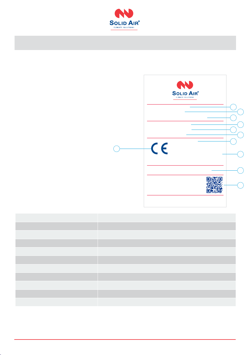
Product label
1. Serial number
2. Dimension of the re damper
3. Type
4. Serial number
5. Production date
6. Mechanism type
7. Classication according to EN 13501-3
8. Declaration of performance
9. Number of the European standard and
year of its publication
10. Barcode
11. CE-mark
Product specicaties
T
Nominal sizes 100 - 800 mm
Casing length 380 mm
Temperature range -20 °C … 50 °C
Release temperature 72 °C (standard) of 95 °C (optional with electric actuator)
Volume ow rate range up to 21.700 m³/h
Dierential pressure range up to 2.000 Pa
Casing air leakage Class C/ATC3, EN 1751
Closed blade air leakage Class 2, EN 1751
Upstream velocity < 12 m/s
EC conformity EN 13501-3, EN 1366-2, EN 15650, EN 1751, CPR no. 305/2011
Declaration of performance DoP 711/2020_4_EN
1
3
5
2
4
6
8
9
10
7
11
Article number:
Size:
Type:
Serial number:
Production date:
Actuator mechanism:
xxxxxxx
d100
FDC25-d100-m230-S4
0000001
14.10.2019
M230
EN15650:2010
Eltt (Ve-Ho) S Cxx
For the re classication of
this product please consult
declaration of performance.
DOP 711/2017 N
EI 60/90/120 (Ve-Ho i < - > 0) S 500 Pa
This damper should be installed according
to the installation instructions.
For more information: www.solid-air.com
Manufactured by Klimaoprema d.d.
Gradna 78A - 10430 Samobor - HR/Croatia
1812 17 1812-CPD-1161
6| Round re damper manual 02/2021
SOLID AIR
®
CLIMATE SOLUTIONS • T +31 598 36 12 21 • www.solid-air.com •mail@solid-air.com
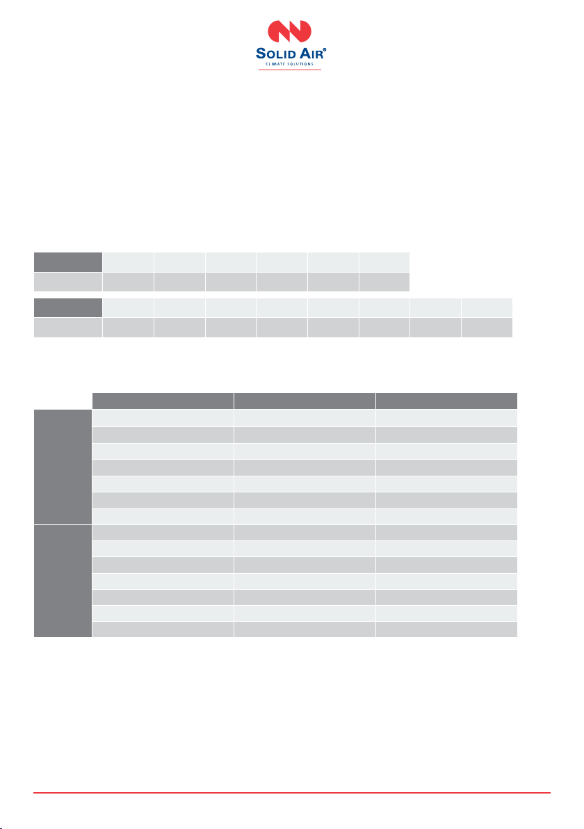
Diameter (mm) Cross section (dm²) Net area (dm²)
FDC25
100 0.74 0.50
125 1.17 0.87
160 1.93 1.55
200 3.05 2.56
250 4.79 4.18
300 6.18 5.74
315 7.64 6.87
FDC40
355 9.73 8.33
400 12.37 10.79
450 15.69 13.91
500 19.39 17.41
630 30.86 28.36
710 39.24 36.42
800 49.86 46.68
Specications Pressure drop
Pressure drop values are described with the “Zeta” values for each size. The exact pressure drop in
[Pa] is calculated using the following formula:
∆p [Pa]= ζ * v² * 0,6
Where ζis Zeta value from the tables below, v is airow velocity in [m/s].
FDC25 d100 d125 d160 d200 d250 d315
ζ1.759 0.852 0.545 0.445 0.340 0.293
FDC40 d355 d400 d450 d500 d560 d630 d710 d800
ζ0.428 0.389 0.344 0.325 0.312 0.232 0.206 0.179
Dimensional range

7| Round re damper manual 02/2021
SOLID AIR
®
CLIMATE SOLUTIONS • T +31 598 36 12 21 • www.solid-air.com •mail@solid-air.com
O
M
Casings
FDC25
Cylindrical re damper with 25 mm damper blade
and re classication up to EI120S. Sizes range from
d100 till d315.
FDC40
Cylindrical re damper with 40 mm damper blade
and re classication up to EI120S. Sizes range from
d355 till d800.
FDC25-APP
Cylindrical re damper with integrated Applique
installation frame with 25 mm damper blade
and re classication up to EI90S. Sizes range
from d100 till d315.
FDC25-MF1/MF2
Cylindrical re damper with integrated MF1
installation frame with 25 mm damper blade
and re classication up to EI60S. Sizes range
from d100 till d315.
FDC40-MF2
Fire damper with integrated MF2 installation frame
with 40 mm damper blade and re classication up
to EI90S. Sizes range from d355 till d800.
(1) Damper type (2) Dimension (3) Mechanism type
FDC25 - d250 - M230-S
(1)
(2)
FDC25 - 100 to 315
FDC40 - 355 to 800
FDC25-APP - 100 to 315
FDC25-MF1 - 100 to 315
FDC25-MF2 - 100 to 315
FDC40-MF2 - 355 to 800
Damper diameter 100 till 800 mm
(3) R - manual drive
R-S - manual drive with limit
switches
M230-S - electric actuator AC 230V
M24-S - electric actuator AC/DC 24V
M24-S-ST - electric actuator AC/DC 24V
with connection plug
EMS-S - electromagnetic drive
EX - ATEX rated Schischek
230/24V electric actuator

8| Round re damper manual 02/2021
SOLID AIR
®
CLIMATE SOLUTIONS • T +31 598 36 12 21 • www.solid-air.com •mail@solid-air.com
P
Actuators
R (R-S)
Manual operating mechanism, optionally with end
switches (R-S). In case of re, the re damper closes
automatically. Damper closing can be initiated
either by thermal fuse melting, or by manual acti-
vation on the operating mechanism. Upon closure,
damper blade is locked in closed position and can
only be opened manually. Thermal fuse melting
point is 72 °C.
EMS-S
Electromagnetic operating mechanism, comes with
end switches as standard. In case of re, the re
damper closes automatically. Damper closing can
be initiated either by thermal fuse melting or remo-
tely by triggering the electromagnet. Electromagnet
is constantly under power and activates closing of
the damper blade in case the power cuts out. Upon
closure, damper blade is locked in closed position
and can only be opened manually. Thermal fuse
melting point is 72 °C.
M230-S
Belimo 230 V electro motor operating mechanism,
comes with integrated end switches. In case of
re, the re damper closes automatically. Damper
closing can be initiated either by thermoelectric
release device or remotely by triggering the electro
motor. Upon closure, damper blade is locked in
closed position and can be opened by sending a
signal to electro motor. Standard thermoelectric
release point is 72 °C, optional 95 °C.
M24-S
Belimo 24 V electro motor operating mechanism,
comes with integrated end switches. In case of
re, the re damper closes automatically. Damper
closing can be initiated either by thermoelectric
release device or remotely by triggering the electro
motor. Upon closure, damper blade is locked in
closed position and can be opened by sending a
signal to electro motor. Standard thermoelectric
release point is 72 °C, optional 95 °C.
M24-S-ST
Belimo 24 V electro motor operating mechanism,
comes with integrated end switches. In case of
re, the re damper closes automatically. Damper
closing can be initiated either by thermoelectric
release device or remotely by triggering the electro
motor. Upon closure, damper blade is locked in
closed position and can be opened by sending a
signal to electro motor. Standard thermoelectric
release point is 72 °C, optional 95 °C. Actuator is
additionally equipped with connection plug for easy
connection with power supply and communication
modules.
EX
ATEX rated re dampers are equipped with
Schischek ExMax actuators, Exbox-TT thermal swit-
ches and ExBox plenum boxes. Optional casing can
be produced in AISI316L stainless steel.
9| Round re damper manual 02/2021
SOLID AIR
®
CLIMATE SOLUTIONS • T +31 598 36 12 21 • www.solid-air.com •mail@solid-air.com
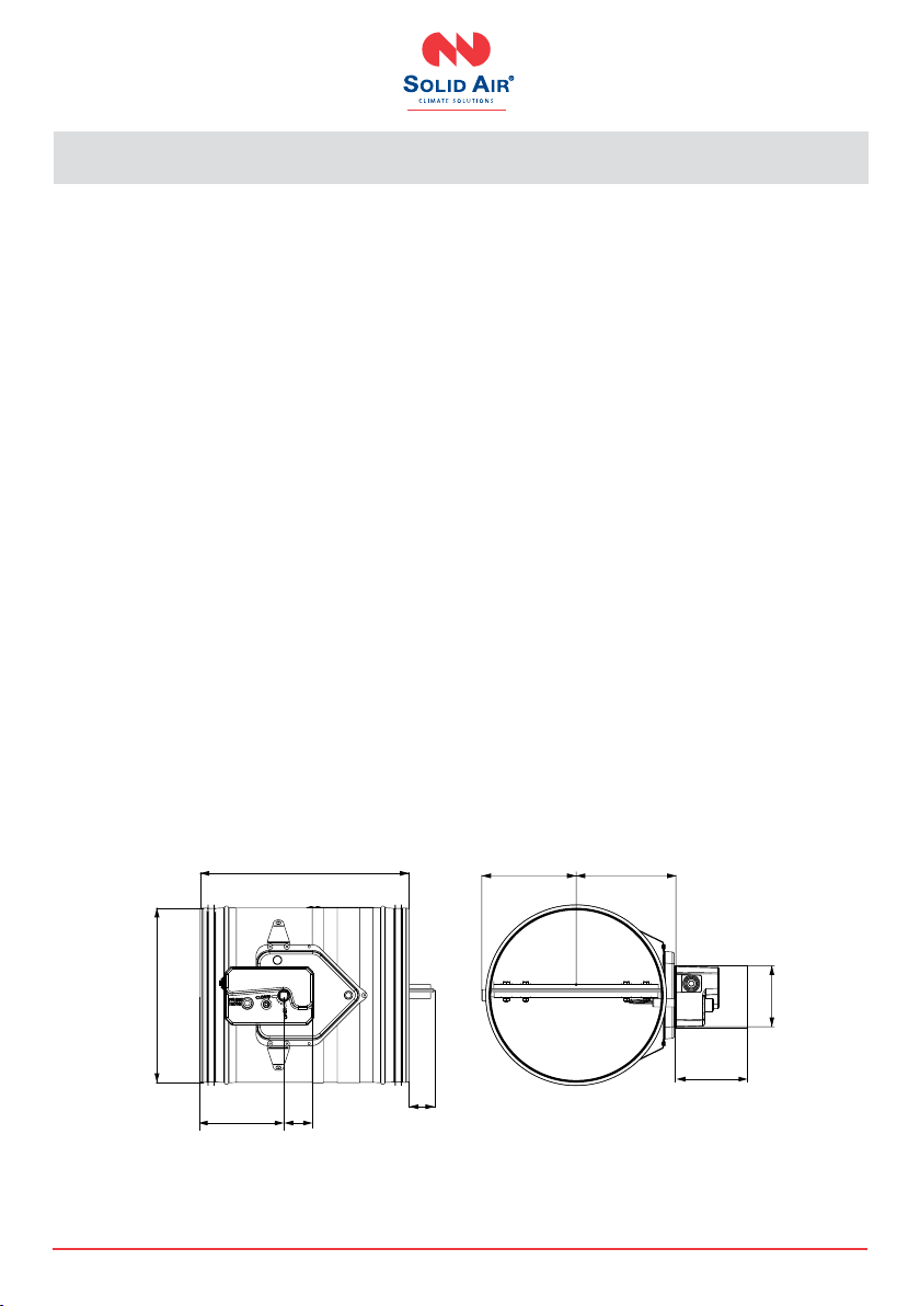
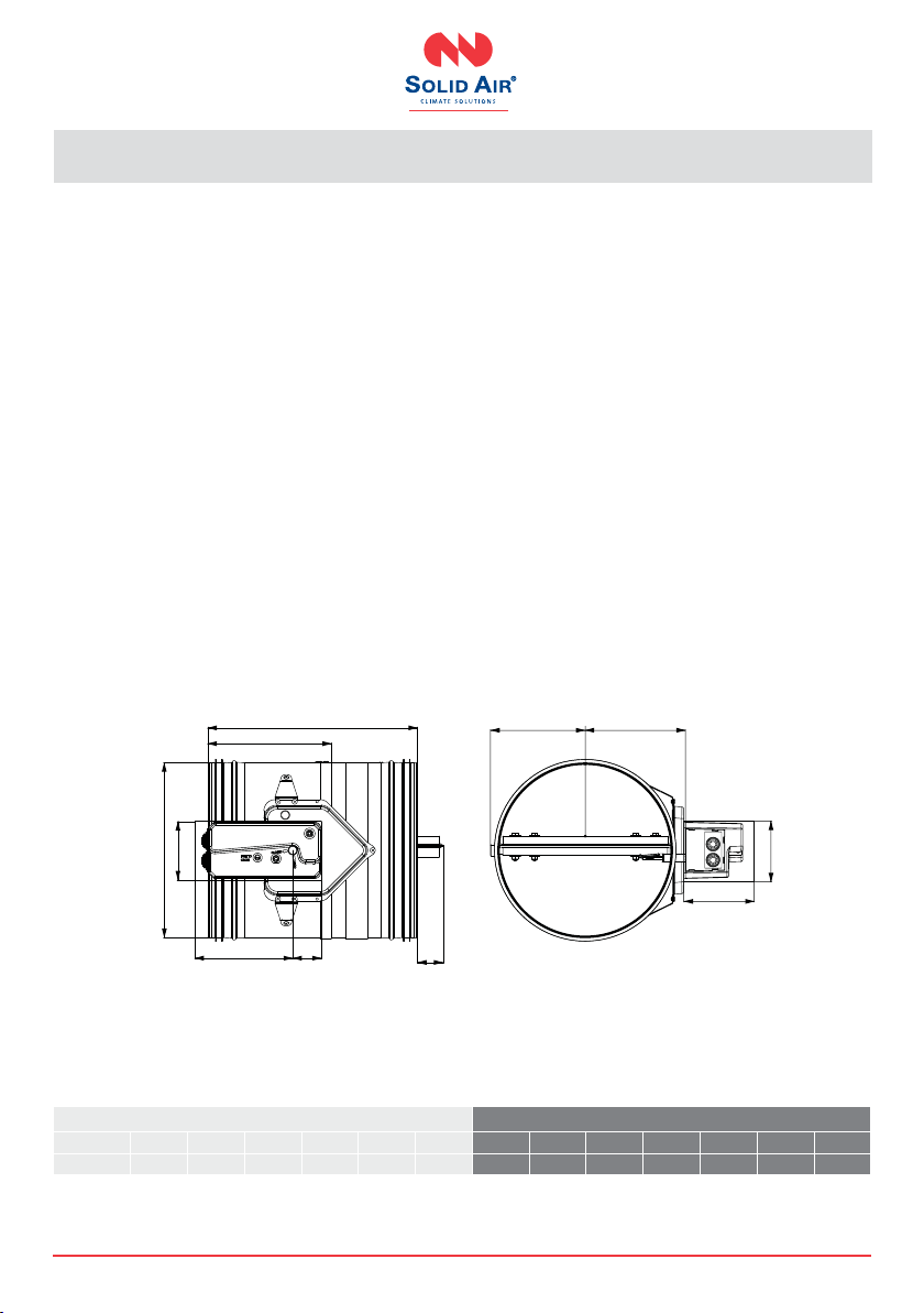
2. D
FDC25/FDC40-R
(manual mechanism)
• Automatic closure when the temperaturein the
duct exceeds 72 °C.
• Manual rearming with handle.
• Manual unlocking possible for periodical test of
re damper.
• Optional with end position switches (-R-S).
• FDC25 re dampers are equipped with R25
manual mechanism.
• FDC40 re dampers are equipped with R40
manual mechanism.
380
Ød
C A
Y
Ød/2+12 Ød/2+22
105
150
FDC25-R (up to d315)
10 | Round re damper manual 02/2021
SOLID AIR
®
CLIMATE SOLUTIONS • T +31 598 36 12 21 • www.solid-air.com •mail@solid-air.com
380
220
Ød
D
C A Y
Ød/2+12 Ød/2+22
D
E
FDC40-R (d355 up to d800)
Length of damper blade outside of casing (Y dimension on front side)
FFDC 25/40 Y=(Ø d/2)-110 (mm)
*If the damper is larger than Ø 540 mm, use formula (X dimension on back side)
FDC 40 (> d540) X=(Ø d/2)-270 (mm)
FDC25-R FDC40-R
Ø d (mm) 100 125 160 200 250 315 355 400 450 500 630 710 800
Weight (kg) 3.8 4.2 4.7 5.4 6.3 7.7 11.9 13.5 15.4 17.5 23.6 27.7 33.7
Product
A
[mm]
C
[mm]
D
[mm]
E
[mm]
FDC 25 55 150 105 150
FDC 40 55 200 105 200
11 | Round re damper manual 02/2021
SOLID AIR
®
CLIMATE SOLUTIONS • T +31 598 36 12 21 • www.solid-air.com •mail@solid-air.com
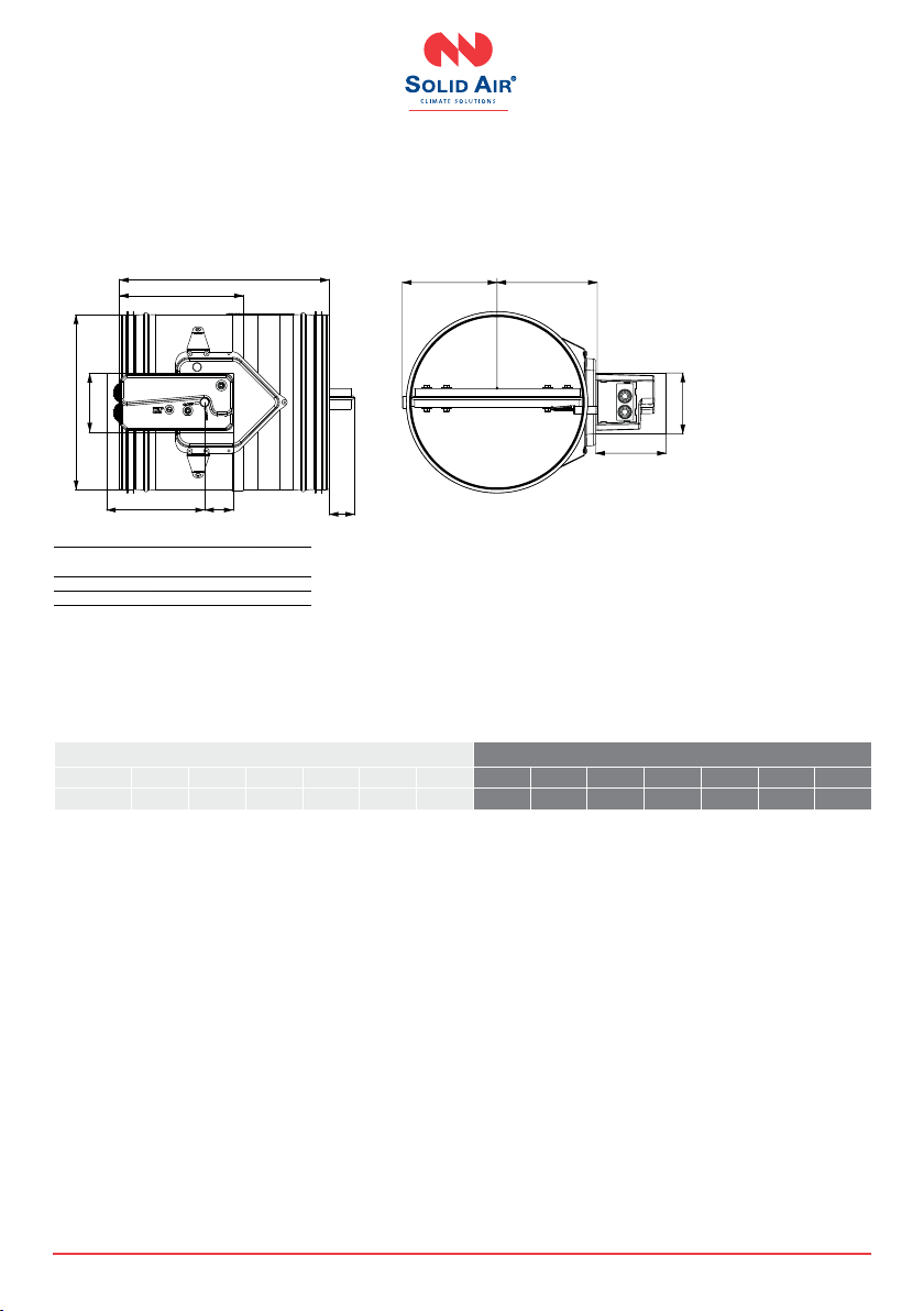
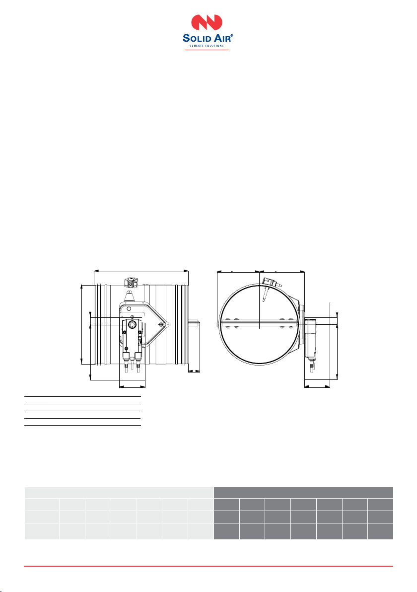
FDC25/FDC40-EMS
(solenoid actuator)
• Electromagnetic actuator with integrated limit
switches and thermal fuse release mechanism
(72 °C).
• Manual rearming with handle.
• Remote closing with electromagnetic actuator.
• Manual closing possible.
• EMS - solenoid actuator is constantly under
power.
• Actuating mechanism is tripped when the power
is interrupted, or thermal fuse is melted.
380
220
Ød
D
C A Y
Ød/2+12 Ød/2+22
D
E
Length of damper blade outside of casing (Y dimension on front side)
FDC 25/40 Y=(Ø d/2)-110 [mm]
*If the damper is larger than Ø 540 mm, use formula (X dimension on back side)
FDC 25/40 X=(Ø d/2)-270 [mm]
D
FDC25-EMS FDC40-EMS
Ø d (mm) 100 125 160 200 250 315 355 400 450 500 630 710 800
Weight (kg) 5.3 5.7 6.2 6.9 7.8 9.2 12.2 13.8 15.7 17.8 23.9 28 34
12 | Round re damper manual 02/2021
SOLID AIR
®
CLIMATE SOLUTIONS • T +31 598 36 12 21 • www.solid-air.com •mail@solid-air.com
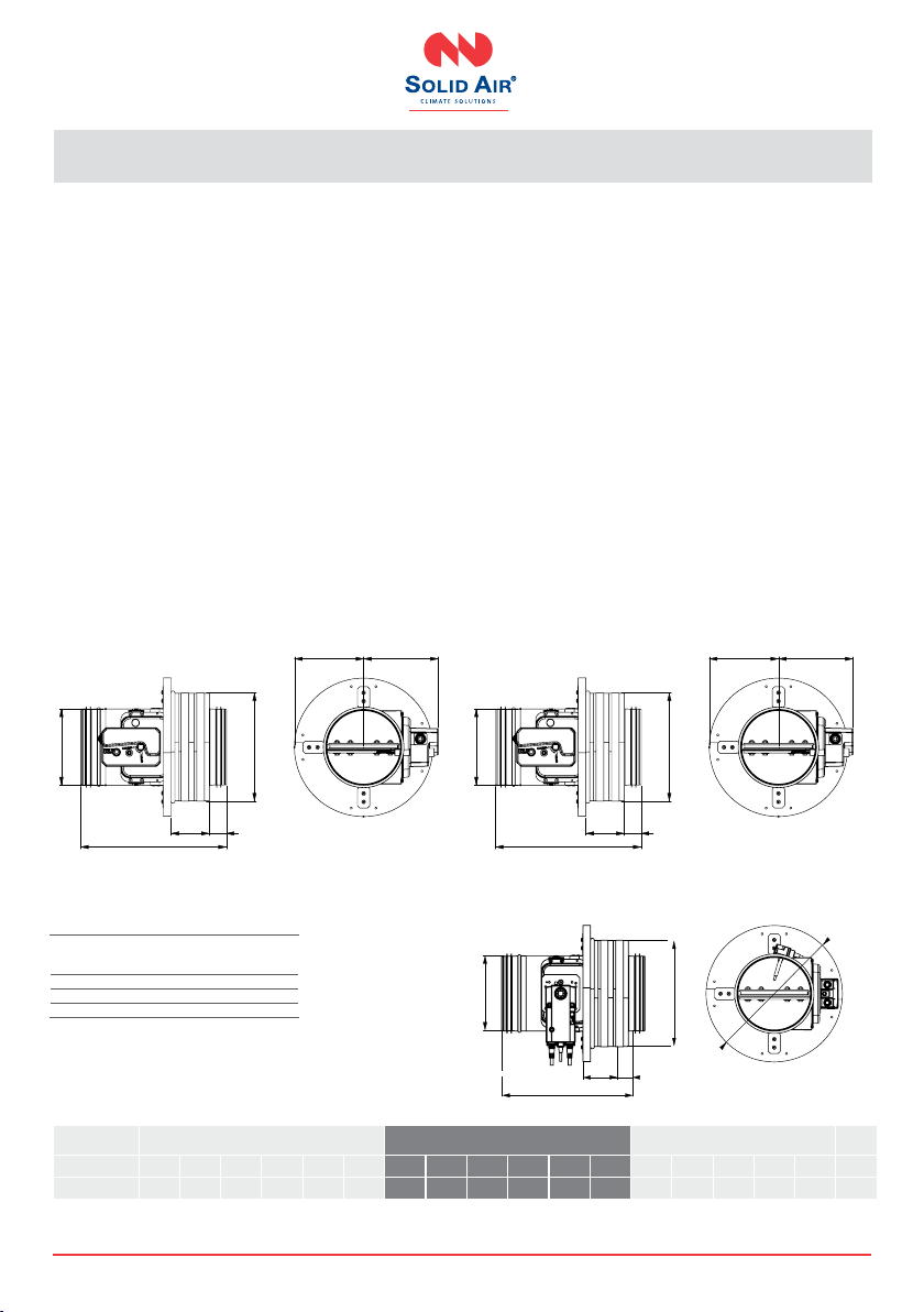
Length of damper blade outside of casing (Y dimension on front side)
FDC 25/40 Y=(Ø d/2)-110 [mm]
*If the damper is larger than Ø 540 mm, use formula (X dimension on back side)
FDC 40 (> d540) X=(Ø d/2)-270 [mm]
FDC25-M FDC40-M
Ø d (mm) 100 125 160 200 250 315 355 400 450 500 630 710 800
Weight (kg) 4.5 4.9 5.4 6.1 7 8.4 11.7 13.3 15.2 17.3 23.4 29.1 35.1
Servomotor
type BFL BFL BFL BFL BFL BFL BFN BFN BFN BFN BFN BF BF
380
Ød
C A
D
Y
Ød/2+12
E
CA
Ød/2+12
FDC25 / FDC40-M
(electric actuator)
• Thermoelectric release device (72 °C) with electric
actuator and return spring.
• Integrated end switches.
• Fully automatic operation.
• Optional 95 °C thermoelectric release device for
warm air installations (see pg. 53 Accessories).
Product
A
[mm]
C
[mm]
D
[mm]
E
[mm]
BFL (M) 25 200 90 120
BFN (M) 25 225 100 120
BF (M)* 50 250 100 120
13 | Round re damper manual 02/2021
SOLID AIR
®
CLIMATE SOLUTIONS • T +31 598 36 12 21 • www.solid-air.com •mail@solid-air.com
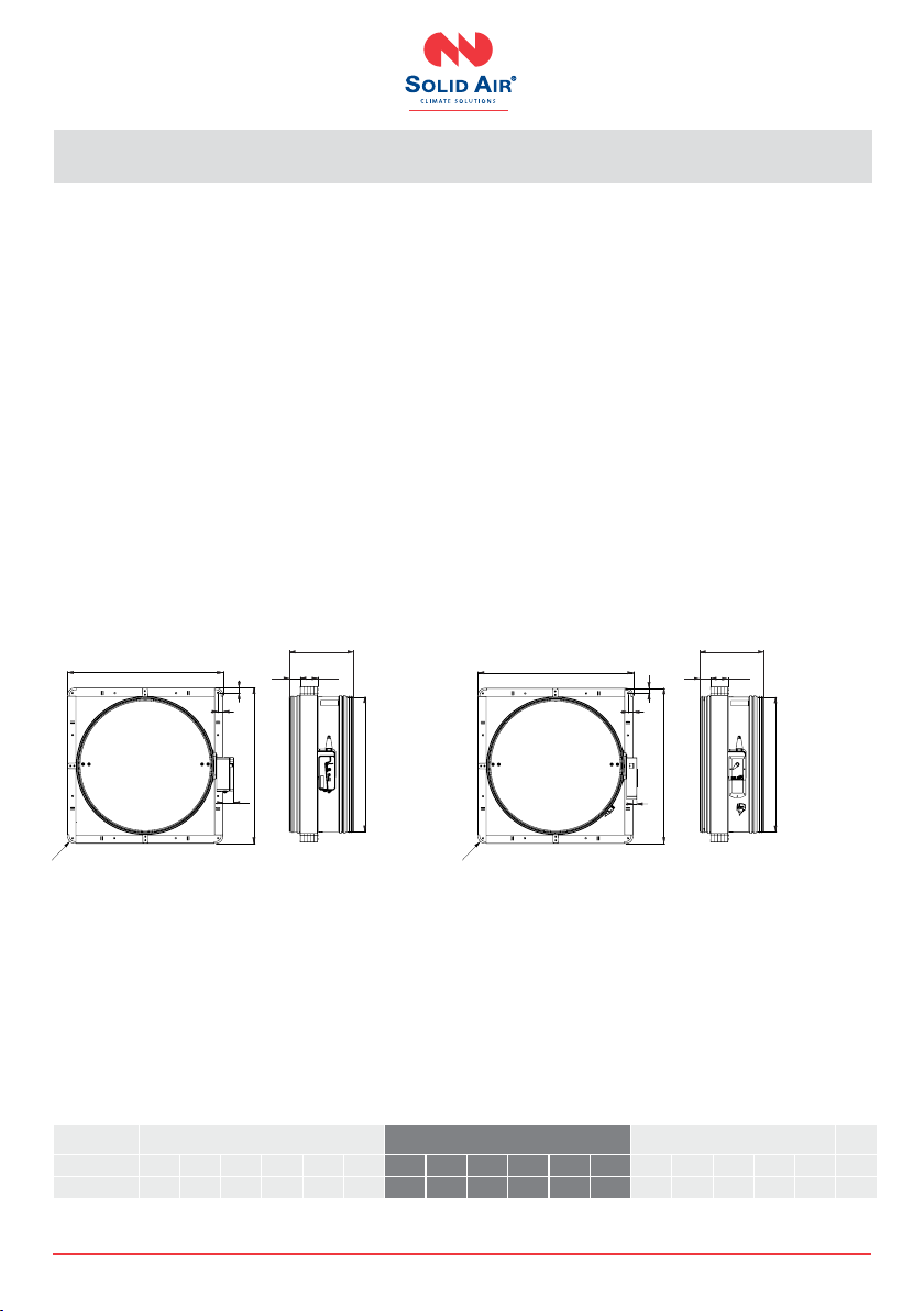
FDC25-APP
Applique installation frame
• Applique kit is an installation subframe for quick
and easy installation in rigid and exible walls.
• Made out of calcium silicate boards.
• Quick wall mounting with screws.
• Factory assembled to the re damper.
(
n/2)+80
(
n/2)+94
380
100
45
n
n+ A
(
n/2)+80
(
n/2)+94
380
100
45
n
n+ A
Ød
380
100 45
Ød +A
(Ød/2)+80 (Ød/2)+94
(
n/2)+80
(
n/2)+94
380
100
45
n
n+ A
(
n/2)+80
(
n/2)+94
380
100
45
n
n+ A
Ød
380
100 45
Ød +A
(Ød/2)+80 (Ød/2)+94
45
145
380
n+160
n+ A
380
Ød +A
Ød+160
100 45
Ød
D
Damper diameter
Ød (mm)
Applique frame
diameter
Ø d + A (mm)
100 Ø d +105 mm
125 - 160 Ø d + 95 mm
200 - 315 Ø d + 80 mm
FDC25-APP-R FDC25-APP-EMS
FDC25-APP-M
FDC25-APP-R FDC25-APP-EMS FDC25-APP-M
Ø d (mm) 100 125 160 200 250 315 100 125 160 200 250 315 100 125 160 200 250 315
Weight (kg) 6.2 6.7 7.8 8.5 10.1 12.3 7.7 8.2 9.3 10 11.6 13.8 6.9 7.4 8.5 9.2 10.8 13

14 | Round re damper manual 02/2021
SOLID AIR
®
CLIMATE SOLUTIONS • T +31 598 36 12 21 • www.solid-air.com •mail@solid-air.com
FDC25
MF1 installation frame
• MF1 is an installation frame for quick and easy
installation in rigid and exible walls.
• Made out of calcium silicate boards.
• Quick wall mounting with screws.
• Factory assembled to the re damper.
62 82
Dn
380
Dn+118
36
62 82
380
Dn+118
Dn+118
36
36
Ød
380
82 62
Ød +118
36
36
Ød +118
R40
62 82
Dn
380
Dn+118
Dn+118
36
36
62 82
Dn
380
Dn+118
Dn+118
36
36
Ød
380
82 62
36
Ød +118
36
R40
62 82
Dn
380
Dn+118
Dn+118
36
36
Ød
82 62
380 Ød +118
62 82
Dn
380
Dn+118
Dn+118
36
36
Ød +118
R40
D
FDC25-MF1-R FDC25-MF1-EMS
FDC25-MF1-M
FDC25-MF1-R FDC25-MF1-EMS FDC25-MF1-M
Ø d (mm) 100 125 160 200 250 315 100 125 160 200 250 315 100 125 160 200 250 315
Weight (kg) 6.6 7.4 8.7 10.3 12.5 15.5 8.1 8.9 10.2 11.8 14 17 7.3 8.1 9.4 11 13.2 16.2

15 | Round re damper manual 02/2021
SOLID AIR
®
CLIMATE SOLUTIONS • T +31 598 36 12 21 • www.solid-air.com •mail@solid-air.com
FDC25
MF2 installation frame
• MF2 is an installation frame for quick and easy
installation in rigid, exible and shaft walls.
• Made out of calcium silicate boards.
• Quick wall mounting with screws.
• Factory assembled to the re damper.
Ød
380
103,5 65
Ød +118
36
36
Ød +118
11
R40
Ød
380
103,5 65
Ød +118
Ød +118
36
36
R40
Ød +118
36
36
Ød +118
11
Ød
380
103,5 65
R40
D
FDC25-MF2-R FDC25-MF2-EMS
FDC25-MF2-M
FDC25-MF2-R FDC25-MF2-EMS FDC25-MF2-M
Ø d (mm) 100 125 160 200 250 315 100 125 160 200 250 315 100 125 160 200 250 315
Weight (kg) 7.1 8.1 9.6 11.4 13.8 17.2 8.6 9.6 11.1 12.9 15.3 18.7 7.8 8.8 10.3 12.1 14.5 17.9
16 | Round re damper manual 02/2021
SOLID AIR
®
CLIMATE SOLUTIONS • T +31 598 36 12 21 • www.solid-air.com •mail@solid-air.com
FDC40
MF2 installation frame
• MF2 is an installation frame for quick and easy
installation in rigid, exible and shaft walls.
• Made out of calcium silicate boards.
• Quick wall mounting with screws.
• Factory assembled to the re damper.
Ød
380
103,5
65
Ød +120
30
30
Ød +120
66
R40
Ød
65
Ød +120
30
30
Ød +120
25
380
103,5
R40
D
FDC40-MF2-R/FDC40-MF2-EMS FDC40-MF2-M
FDC40-MF2-R FDC40-MF2-EMS FDC40-MF2-M
Ø d (mm) 355 400 450 500 630 800 355 400 450 500 630 800 355 400 450 500 630 800
Weight (kg) 22.8 25.9 29.6 33.6 45 62.8 23.1 26.2 29.9 33.9 45.3 63.1 22.6 25.7 29.4 33.4 44.8 64.2

17 | Round re damper manual 02/2021
SOLID AIR
®
CLIMATE SOLUTIONS • T +31 598 36 12 21 • www.solid-air.com •mail@solid-air.com
The FDC25 / FDC40 re damper is always tested in
standardized support frames (both in a rigid wall
and in a exible wall) in accordance with EN 1366-2:
2015 table 3/4/5. The results obtained are valid for
all similar support frames which have a thickness
and / or density and / or re resistance similar or
greater than the one on the test.
The duct connected to the re damper must be sup-
ported or hung in such a way that the damper does
not carry its weight. The damper must not support
any part of the surrounding construction or wall
which could cause damage and consequent damper
failure. It is recommended to connect the damper to
a exible connection on either end of the damper.
The damper driving mechanism can be placed
on either side of the wall, however it needs to be
placed so that it ensures an easy access during
inspection.
• Mounting is possible with the blade axis in
horizontal or in vertical position.
• The installation must comply with the tests
that were performed during certication.
• Avoid any obstruction of the moving blade by
the connected ducts.
• The class of air-tightness is maintained in
case the installation of the damper is made in
accordance with the technical manual.
• Operating temperature: 50 °C max.
• For indoor use only.
The gap in the installation opening between the re
damper and the wall/ceiling can be increased by up
to 50 % of the gap area, or decreased to the smallest
dimension that is shown in the table:
Installation in both, vertical and horizontal axis
of rotation of the dampers blade is acceptable
(with the axis angle 0 - 360°).
The re damper must
be installed into a re
partition structure
in such a way that
the damper blade in
its closed position is
located inside this
structure (except for
installation with MF1
installation frame).
To help you nd the suspension plane, a bendable
hinge is provided on the damper body and the red
tape is placed on the casing to mark the location
of the wall limit. This does not apply for Applique/
MF1/ MF2 kit installations.
Check the operation of the re damper before
commencing the installation!
3. I
Wall limit
Damper size
Ø d (mm) Opening size
Ø d + A (minimum)
100 Ø d +105 mm
125 - 160 Ø d + 95 mm
200 - 315 Ø d + 80 mm
18 | Round re damper manual 02/2021
SOLID AIR
®
CLIMATE SOLUTIONS • T +31 598 36 12 21 • www.solid-air.com •mail@solid-air.com
Range
Supporting
construction
Wall
thickness
Supporting construction
details Type of installation Classication Tested
underpressure Details Construction
type
Sealing
type
d100-d800 mm
Rigid wall ≥ 100 mm
Aerated concrete
( ≥ 550 kg/m3)
Reinforced concrete
(≥ 2200 kg/m3)
Gypsum plaster/mortar EI 120 (ve i↔o)S 500 Pa
Mineral wool and cover
boards
EI 90 (ve i↔o)S
500 Pa
Fire Batt/Weichschott 300 Pa
Flexible wall
≥ 70 mm Gypsum blocks
(≥ 995 kg/m3)
Gypsum plaster/mortar and
cover boards EI 120 (ve i↔o)S 500 Pa
≥ 100 mm Plasterboard
type A (EN520)
Gypsum plaster/mortar EI 120 (ve i↔o)S 500 Pa
Mineral wool and cover
boards EI 90 (ve i↔o)S 500 Pa
Fire Batt/Weichschott EI 90 (ve i↔o)S 300 Pa
Floor/
ceiling ≥ 100 mm
Aerated concrete
( ≥ 550 kg/m3)
Reinforced concrete
(≥ 2200 kg/m3)
Gypsum plaster/mortar EI 120 (ho i↔o)S 500 Pa
Fire Batt/Weichschott EI 90 (ho i↔o)S 300 Pa
APP INSTALLATION FRAME
d100-d315 mm
Rigid wall ≥ 100 mm
Aerated concrete
( ≥ 550 kg/m3)
Reinforced concrete
(≥ 2200 kg/m3)
Applique (installation frame) EI 90 (ve i↔o)S 500 Pa
Flexible wall
≥ 70 mm Gypsum blocks
(≥ 995 kg/m3)Applique (installation frame) EI 90 (ve i↔o)S 500 Pa
≥ 100 mm Plasterboard
type A (EN520) Applique (installation frame) EI 90 (ve i↔o)S 500 Pa
MF1/ MF2 INSTALLATION FRAME
FDC25 MF1 d100-d315 mm
FDC40 MF2 d355-d800 mm
Rigid wall ≥ 100 mm
Aerated concrete
( ≥ 550 kg/m3)
Reinforced concrete
(≥ 2200 kg/m3)
MF1 (installation frame)
MF2 (installation frame)
FDC25:EI 60 (ve i↔o)S
500 Pa
FDC40:EI 90 (ve i↔o)S
Flexible wall
≥ 70 mm Gypsum blocks
(≥ 995 kg/m3)
MF1 (installation frame)
MF2 (installation frame)
FDC25:EI 60 (ve i↔o)S 500 Pa
FDC40:EI 90 (ve i↔o)S
≥ 100 mm Plasterboard
type A (EN520)
MF1 (installation frame)
MF2 (installation frame)
FDC25:EI 60 (ve i↔o)S 500 Pa
FDC40:EI 60 (ve i↔o)S
MF2 INSTALLATION FRAME
FDC25 MF2 d100-d315mm
FDC40 MF2 d355-d800 mm
Flexible wall ≥ 90 mm Shaft wall (steel frame)
(type 98/48) MF2 (installation frame)
FDC25:EI 60 (ve i↔o)S
500 Pa
FDC40:EI 60 (ve i↔o)S
ISOVER
d100-d630
mm (only
FDC40)
Flexible wall ≥ 100 mm Plasterboard
type A (EN520) Remote from wall (Isover) EI 60 (ve i↔o)S 300 Pa
Aerated concrete ( ≥ 550 kg/m3) or reinforced concrete
(≥ 2200 kg/m3) wall, more than 100 mm thick.
Gypsum blocks (≥ 995 kg/m3) wall, more than
70 mm thick.
Plasterboard wall, type A (EN520), more than
100 mm thick.
Aerated concrete ( ≥ 550 kg/m3) or reinforced concrete
(≥ 2200 kg/m3) ceiling / oor, more than 100 mm thick.
Gypsum plaster, mortar sealing or mortar
and cover boards.
Sealing with mineral wool and cover boards.
Sealing with mineral wool and reproof
coating - FireBatt/Weichschott.
Applique kit installation.
MF1/MF2 kit installation.
Remote from wall installation.
Shaft wall, steel frame construction.
INSTALLATION
Check for more information about certicate installations in the declaration of performance:
Klik hier
Details
19 | Round re damper manual 02/2021
SOLID AIR
®
CLIMATE SOLUTIONS • T +31 598 36 12 21 • www.solid-air.com •mail@solid-air.com
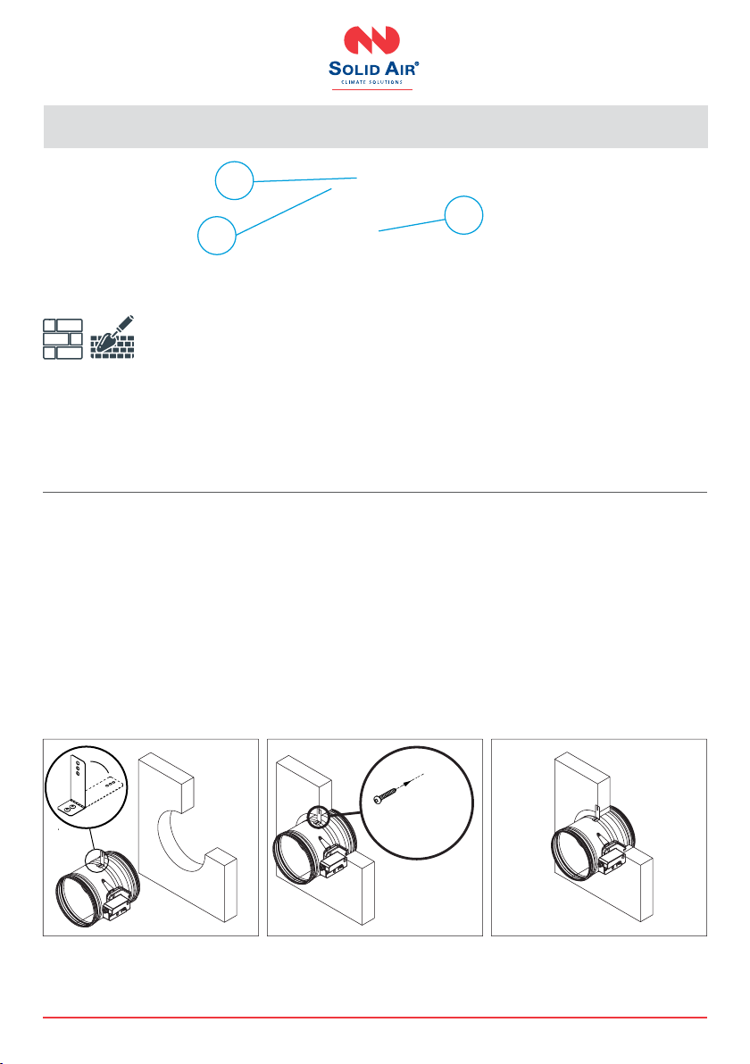
Rigid wall installation (mortar sealing)
The wall is composed of concrete blocks (minimum
density of 550 kg/m³) or reinforced concrete
(minimum density of 2200 kg/m³) and with a
minimum thickness of 100 mm.
Installation material is gpsum plaster or mortar.
I
1
1
2
2
7
3
INSTALLATION
1. Create an opening in the wall (minimal dimen-
sions on page 13). and bend the xing bracket (1)
90°. Place the damper in the opening up to the
wall limit mark (7) on the damper.
Damper blade must be closed during the installation!
2. Fix the damper to the wall using screws. Bracket
screw hole is 6 mm in diameter.
3. Fill the space between the damper and the wall
with gpsum plaster or mortar (2).
*Multiple re dampers can be installed next to each
other or ceiling/wall with the minimal distance of
30 mm between them. See page 42.
Test the operation of the damper blade!

20 | Round re damper manual 02/2021
SOLID AIR
®
CLIMATE SOLUTIONS • T +31 598 36 12 21 • www.solid-air.com •mail@solid-air.com
625 625
> 440
625 625
> 440
Rigid wall installation (mineral wool sealing)
The wall is composed of concrete blocks (minimum
density of 550 kg/m³) or reinforced concrete (mini-
mum density of 2200 kg/m³) and with a minimum
thickness of 100 mm. Installation material is mine-
ral wool, covered with plasterboard cover boards.
I
1
1
4
2
3
3
INSTALLATION
1. Create an opening in the wall (Ø d + 80 mm) x (Ø d
+ 80 mm). Bend the xing bracket (1) 90°. Place the
damper in the opening up to the wall limit mark
(7) on the damper.
Damper blade must be closed during the installation!
2. Fix the damper to the wall using screws. Bracket
screw hole is 6 mm in diameter.
3. Fill the space between the damper and the wall
with mineral wool (3) ( ≥ 100 kg/m³). Cover the
mineral wool with GKF gpsum boards (4) (12.5
mm thick), and x them with screws.
*Multiple re dampers can be installed next to each
other or ceiling/wall with the minimal distance of
30 mm between them. See page 42.
Test the operation of the damper blade!
7
This manual suits for next models
1
Table of contents
Other SOLID AIR Fire And Smoke Damper manuals


Popular Fire And Smoke Damper manuals by other brands


Trox Technik
Trox Technik FKRS-EU Installation and operating manual

Mandik
Mandik FDML Technical documentation

Greenheck
Greenheck VCD Series Installation, operation and maintenance manual

Madel
Madel FOK-EIS-120 manual

SMAY
SMAY KWP-L Technical documentation

Maico
Maico BSB VC Series Installation, Operating and Maintenance Instruction


