manuals.online logo
Brands
  1. Home
  2. •
  3. Brands
  4. •
  5. Lindab
  6. •
  7. Fire And Smoke Damper
  8. •
  9. Lindab WH25 User manual

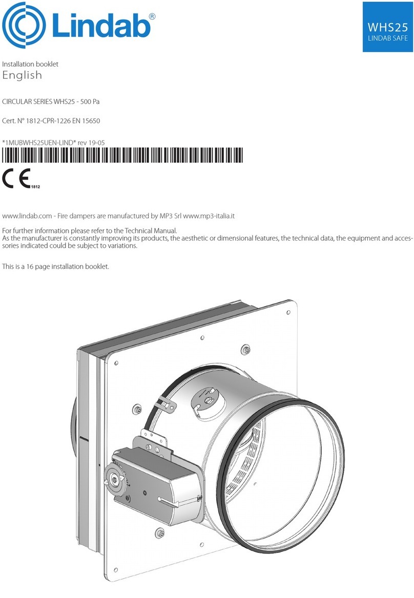
Lindab WH25 User manual

Other manuals for WH25

1

Other Lindab Fire And Smoke Damper manuals

Lindab RECTANGULAR Series User manual

Lindab

Lindab RECTANGULAR Series User manual

Lindab WH45 Series Installation and operation manual

Lindab

Lindab WH45 Series Installation and operation manual

Lindab RECTANGULAR Series Installation and operation manual

Lindab

Lindab RECTANGULAR Series Installation and operation manual

Lindab RECTANGULAR Series Installation and operation manual

Lindab

Lindab RECTANGULAR Series Installation and operation manual

Lindab SDR-S User manual

Lindab

Lindab SDR-S User manual

Lindab FBC1 User manual

Lindab

Lindab FBC1 User manual

Lindab LFD Quick start guide

Lindab

Lindab LFD Quick start guide

Lindab DRU User guide

Lindab

Lindab DRU User guide

Lindab WK45 Series Installation and operation manual

Lindab

Lindab WK45 Series Installation and operation manual

Lindab WH45P Installation and operation manual

Lindab

Lindab WH45P Installation and operation manual

Lindab SDR2-M Manual

Lindab

Lindab SDR2-M Manual

Lindab FBC2 Installation and operation manual

Lindab

Lindab FBC2 Installation and operation manual

Lindab CFDM Manual

Lindab

Lindab CFDM Manual

Lindab SDJR-S User manual

Lindab

Lindab SDJR-S User manual

Lindab SKMTR User guide

Lindab

Lindab SKMTR User guide

Lindab FNC1 Installation and operation manual

Lindab

Lindab FNC1 Installation and operation manual

Lindab FDS-M User manual

Lindab

Lindab FDS-M User manual

Lindab WH25 Installation and operation manual

Lindab

Lindab WH25 Installation and operation manual

Lindab WK45 Series User manual

Lindab

Lindab WK45 Series User manual

Lindab CIRCULAR Series Installation and operation manual

Lindab

Lindab CIRCULAR Series Installation and operation manual

Popular Fire And Smoke Damper manuals by other brands

mercor mcr ZIPP Operation and maintenance manual

mercor

mercor mcr ZIPP Operation and maintenance manual

HVC NCA 700 Series Operation and maintenance manual

HVC

HVC NCA 700 Series Operation and maintenance manual

Wildeboer FR90 user manual

Wildeboer

Wildeboer FR90 user manual

FläktGroup ETCE Instructions for installation, operation and maintenance

FläktGroup

FläktGroup ETCE Instructions for installation, operation and maintenance

Tamco 1000 SM Series manual

Tamco

Tamco 1000 SM Series manual

Greenheck Vektor-MD Installation, operation and maintenance manual

Greenheck

Greenheck Vektor-MD Installation, operation and maintenance manual

BLAUBERG Ventilatoren BSK user manual

BLAUBERG Ventilatoren

BLAUBERG Ventilatoren BSK user manual

mercor mcr FID PRO Series Operation and maintenance manual

mercor

mercor mcr FID PRO Series Operation and maintenance manual

Greenheck HPR Series Installation, operation and maintenance manual

Greenheck

Greenheck HPR Series Installation, operation and maintenance manual

Greenheck HPR Series Installation, operation and maintenance manual

Greenheck

Greenheck HPR Series Installation, operation and maintenance manual

SMAY WKP-P installation manual

SMAY

SMAY WKP-P installation manual

Komfovent UVS30 Installation instruction

Komfovent

Komfovent UVS30 Installation instruction

Mandik FDMD manual

Mandik

Mandik FDMD manual

Mandik SEDS-L Technical specifications

Mandik

Mandik SEDS-L Technical specifications

mercor mcr FID WING Technical documentation operation manual

mercor

mercor mcr FID WING Technical documentation operation manual

Vents KP Series user manual

Vents

Vents KP Series user manual

Mandik MSD manual

Mandik

Mandik MSD manual

Tecnosystemi GALAXY 11161874 user manual

Tecnosystemi

Tecnosystemi GALAXY 11161874 user manual

manuals.online logo
manuals.online logoBrands
  • About & Mission
  • Contact us
  • Privacy Policy
  • Terms and Conditions

Copyright 2025 Manuals.Online. All Rights Reserved.

English
Technical Manual
Installation type with re resistance class
Cert. N° 1812-CPR-1023
CIRCULAR SERIES WH25 - 500 Pa
PATENTED FIRE DAMPER
WH25
LINDAB SAFE
This is a 50 page manual.
TABLE OF CONTENTS
WH25
LINDAB SAFE
3/50
Overview � � � � � � � � � � � � � � � � � � � � � � � � � � � � � � � � � � � � � � � � � � � � � � � � � � � � p�4
Description � � � � � � � � � � � � � � � � � � � � � � � � � � � � � � � � � � � � � � � � � � � � � � � � � � � � � � p�4
General characteristics � � � � � � � � � � � � � � � � � � � � � � � � � � � � � � � � � � � � � � � � � � � � � � � � p�4
European Standards applied � � � � � � � � � � � � � � � � � � � � � � � � � � � � � � � � � � � � � � � � � � � � � p�4
Certications and approvals � � � � � � � � � � � � � � � � � � � � � � � � � � � � � � � � � � � � � � � � � � � � � � p�4
Components � � � � � � � � � � � � � � � � � � � � � � � � � � � � � � � � � � � � � � � � � � � � � � � � � � � � � p�4
Available dimensions � � � � � � � � � � � � � � � � � � � � � � � � � � � � � � � � � � � � � � � � � � � � � � � � � p�5
Performances � � � � � � � � � � � � � � � � � � � � � � � � � � � � � � � � � � � � � � � � � � � � � � � � � � � � p�5
Fire resistance classication according to EN 13501-3-2009 � � � � � � � � � � � � � � � � � � � � � � � � � � � � � � � p�5
Mechanism type � � � � � � � � � � � � � � � � � � � � � � � � � � � � � � � � � � � � � � � � � � � � � � � � � � � p�8
Technical data � � � � � � � � � � � � � � � � � � � � � � � � � � � � � � � � � � � � � � � � � � � � � � � � � p�11
Dimension � � � � � � � � � � � � � � � � � � � � � � � � � � � � � � � � � � � � � � � � � � � � � � � � � � � � � p�11
Weights � � � � � � � � � � � � � � � � � � � � � � � � � � � � � � � � � � � � � � � � � � � � � � � � � � � � � � p�11
Installation � � � � � � � � � � � � � � � � � � � � � � � � � � � � � � � � � � � � � � � � � � � � � � � � � � p�12
Intended use � � � � � � � � � � � � � � � � � � � � � � � � � � � � � � � � � � � � � � � � � � � � � � � � � � � � p�12
Not allowed uses � � � � � � � � � � � � � � � � � � � � � � � � � � � � � � � � � � � � � � � � � � � � � � � � � � p�12
Positioning brackets before xing � � � � � � � � � � � � � � � � � � � � � � � � � � � � � � � � � � � � � � � � � � p�12
Blade rotation axis positioning � � � � � � � � � � � � � � � � � � � � � � � � � � � � � � � � � � � � � � � � � � � p�12
Installation of exible connectors in order to balance out the ventilation ducts expansion � � � � � � � � � � � � � � � p�12
Transfer Application (application not connected to air ducts on one or both sides) � � � � � � � � � � � � � � � � � � p�13
Minimum distances � � � � � � � � � � � � � � � � � � � � � � � � � � � � � � � � � � � � � � � � � � � � � � � � � p�15
Construction supports characteristics � � � � � � � � � � � � � � � � � � � � � � � � � � � � � � � � � � � � � � � � p�17
Installations within vertical rigid wall � � � � � � � � � � � � � � � � � � � � � � � � � � � � � � � � � � � � � � � � p�19
Installations within vertical light wall (plasterboard) � � � � � � � � � � � � � � � � � � � � � � � � � � � � � � � � � p�21
Installations within vertical light wall (gypsum blocks wall) � � � � � � � � � � � � � � � � � � � � � � � � � � � � � � p�22
Installations within oor � � � � � � � � � � � � � � � � � � � � � � � � � � � � � � � � � � � � � � � � � � � � � � p�23
Installations within vertical wall with Fire Batt (Weichschott) sealing � � � � � � � � � � � � � � � � � � � � � � � � � p�24
Installation within oor with Fire Batt (Weichschott) sealing � � � � � � � � � � � � � � � � � � � � � � � � � � � � � p�25
Installation remote from the vertical rigid wall and the vertical light wall (gypsum blocks wall) � � � � � � � � � � � � p�26
Installation remote from the vertical light wall (plasterboard) � � � � � � � � � � � � � � � � � � � � � � � � � � � � � p�28
Installations remote from the vertical wall with Fire Batt (Weichschott) sealing � � � � � � � � � � � � � � � � � � � � p�30
Installations remote from the oor � � � � � � � � � � � � � � � � � � � � � � � � � � � � � � � � � � � � � � � � � p�32
Installation within vertical light wall (Shaft wall) � � � � � � � � � � � � � � � � � � � � � � � � � � � � � � � � � � � p�34
Electrical connections � � � � � � � � � � � � � � � � � � � � � � � � � � � � � � � � � � � � � � � � � � � � � p�35
Electrical wiring � � � � � � � � � � � � � � � � � � � � � � � � � � � � � � � � � � � � � � � � � � � � � � � � � � p�35
Electrical specications � � � � � � � � � � � � � � � � � � � � � � � � � � � � � � � � � � � � � � � � � � � � � � � p�36
Maintenance and inspections � � � � � � � � � � � � � � � � � � � � � � � � � � � � � � � � � � � � � � � � � p�38
Periodic inspection and cleaning � � � � � � � � � � � � � � � � � � � � � � � � � � � � � � � � � � � � � � � � � � p�38
Repair � � � � � � � � � � � � � � � � � � � � � � � � � � � � � � � � � � � � � � � � � � � � � � � � � � � � � � � p�38
Disposal � � � � � � � � � � � � � � � � � � � � � � � � � � � � � � � � � � � � � � � � � � � � � � � � � � � � � � p�38
Selection � � � � � � � � � � � � � � � � � � � � � � � � � � � � � � � � � � � � � � � � � � � � � � � � � � � p�39
Air ow rates in relation to the diameter � � � � � � � � � � � � � � � � � � � � � � � � � � � � � � � � � � � � � � � p�39
Air ow rates as a function of the pressure drop � � � � � � � � � � � � � � � � � � � � � � � � � � � � � � � � � � � p�39
Air ow rates as a function of generated sound levels � � � � � � � � � � � � � � � � � � � � � � � � � � � � � � � � p�39
Pressure drop and sound level graph � � � � � � � � � � � � � � � � � � � � � � � � � � � � � � � � � � � � � � � � p�40
Sound spectrum table � � � � � � � � � � � � � � � � � � � � � � � � � � � � � � � � � � � � � � � � � � � � � � � p�40
Accessories and spare parts � � � � � � � � � � � � � � � � � � � � � � � � � � � � � � � � � � � � � � � � � � p�41
How to order � � � � � � � � � � � � � � � � � � � � � � � � � � � � � � � � � � � � � � � � � � � � � � � � � � p�45
Motorized re dampers � � � � � � � � � � � � � � � � � � � � � � � � � � � � � � � � � � � � � � � � � � � � � � � p�45
Fire damper with manual control � � � � � � � � � � � � � � � � � � � � � � � � � � � � � � � � � � � � � � � � � � p�45
Electric motor driven actuators � � � � � � � � � � � � � � � � � � � � � � � � � � � � � � � � � � � � � � � � � � � p�45
Specication Text � � � � � � � � � � � � � � � � � � � � � � � � � � � � � � � � � � � � � � � � � � � � � � � p�46
Series WH25 compact circular re dampers � � � � � � � � � � � � � � � � � � � � � � � � � � � � � � � � � � � � � p�46
Revision Index � � � � � � � � � � � � � � � � � � � � � � � � � � � � � � � � � � � � � � � � � � � � � � � � � p�48
WH25
3/50
LINDAB SAFE
OVERVIEW
WH25
LINDAB SAFE
4/50
OVERVIEW
Description
Fire dampers WH25 are devices for use in heating, ventila-
tion and air-conditioning (HVAC) systems at re bounda-
ries to maintain compartmentation and protect means of
escape in case of re. They satisfy integrity, insulation and
smoke leakage criteria for the declared time of re resist-
ance.
Tested and classed in accordance with EN 1366-2 and EN
13501-3 regulations with 500 Pa depression.
Studied and optimized for small diameter ducts and re-
duced installation space focusing on aeraulic and acous-
tical performance.
Equipped with various dierent mechanisms completely
outside the wall, easily interchangeble even after installa-
tion.
General characteristics
• Casing made from galvanized carbon steel.
• Thermal labyrinth obtained from the casing.
• Air duct connection gasket.
Lindab Safe: The system is based on a double, factory-in-
stalled seal made of EPDM rubber. This seal makes the
system quick and easy to mount. Refer to Lindab web
site for further information.
Please note that casing painting (see table Accessories
and spare parts  p. 41) is not available for Lindab Safe
connectors.
• Intumescent sealing gasket.
• Opening/closing mechanism with IP42 protection box
(IP54 for motorized version).
• 25 mm thick closing blade made with refractory material.
• Lip seal on blade border for cold smoke seal.
• Internal intumescent gasket for hot smoke seal.
European Standards applied
CE certication EN 15650
Test EN 1366-2
Classication EN 13501-3
Thermal fuse reliability ISO 10294-4
Air tightness EN 1751
Resistance to corrosive environments EN 60068-2-52
Certications and approvals
CE Certicate of Constancy of Performance n° 1812-CPR-1023 Efectis
German approval n° Z-56.4212-987 DIBt
NF certication n° 09/04.02 AFNOR
Swiss approval n° 25971 VKF-AEAI
Swedish approval n° SC0195-16 SP
Components
1. Casing made from galvanized carbon steel.
2. Thermal labyrinth
3. Intumescent graphite gasket on the outside the casing
4. Damper blade made from refractoring material
5. Blade pivot
6. Cold smoke air seal gasket
7. Intumescent graphite gasket on inside of casing for the hot seal
of the blade once closed
8. Temperature controlled closing device (thermal fuse)
9. Blade actioning device
10. Manual closing device (Test button)
11. Manual reset lever
12. Closed blade stopper
13. Protection box
14. Inspection opening Ø 18mm for endoscope (available only for
non-motorized version)
WH25
LINDAB SAFE
4/50
OVERVIEW
WH25
LINDAB SAFE
5/50
Available dimensions
Ø mm 100 125 140 150 160 180 200 224 250 280 300 315
Performances
Performance Reference standard Class
Thermal fuse testing ISO 10294-4 Compliant
Open and Close cycle reliability EN 15650 Compliant
Resistance to corrosion in humid and saline environments EN 60068-2-52 Degree of severity 2
Casing tightness EN 1751 Class C
Blade seal EN 1751 Class 3 minimum
Fire resistance classication according to EN 13501-3-2009
EI 120 S
(500 Pa) EI 90 S
(500 Pa) EI 60 S
(500 Pa) EI 30 S
(500 Pa)
Rigid wall
EI 120 S Installation within vertical rigid wall p.19
Wall minimum thickness 100 mm
Wall minimum density 550 kg/m³
Mortar or plaster putty sealing
ve (i↔o)
WØ
min 100
max 315
Ø
min 100
max 315
Ø
min 100
max 315
Ø
min 100
max 315
EI 90 S Installation within vertical rigid wall p.19
Wall minimum thickness 100 mm
Wall minimum density 550 kg/m³
Plasterboard and rock wool 100 kg/m³ sealing
ve (i↔o)
D - Ø
min 100
max 315
Ø
min 100
max 315
Ø
min 100
max 315
Flexible wall
EI 60 S Installation within vertical light wall (plasterboard) p.21
Wall minimum thickness 100 mm
Wall rock wool density up tp 80 kg/m³ (optional)
Plasterboard and rock wool 80 kg/m³ density sealing
ve (i↔o)
D - - Ø
min 100
max 315
Ø
min 100
max 315
EI 90 S Installation within vertical light wall (plasterboard) p.21
Wall minimum thickness 100 mm
Wall rock wool density up to 80 kg/m³ (optional)
Plasterboard and rock wool 100 kg/m³ density sealing
ve (i↔o)
D - Ø
min 100
max 315
Ø
min 100
max 315
Ø
min 100
max 315
EI 120 S Installation within vertical light wall (plasterboard) p.21
Wall minimum thickness 100 mm
Wall rock wool density up to 80 kg/m³ (optional)
Mortar or plaster putty sealing
ve (i↔o)
WØ
min 100
max 315
Ø
min 100
max 315
Ø
min 100
max 315
Ø
min 100
max 315
EI 90 S Installation within vertical light wall (gypsum blocks wall) p.22
Wall minimum thickness 70 mm
Wall minimum density 995 kg/m³
Plaster putty sealing
ve (i↔o)
W - Ø
min 100
max 315
Ø
min 100
max 315
Ø
min 100
max 315
EI 120 S Installation within vertical light wall (gypsum blocks wall) p.22
Wall minimum thickness 100 mm
Wall minimum density 995 kg/m³
Plaster putty sealing
ve (i↔o)
WØ
min 100
max 315
Ø
min 100
max 315
Ø
min 100
max 315
Ø
min 100
max 315
WH25
5/50
LINDAB SAFE
OVERVIEW
WH25
LINDAB SAFE
6/50
EI 120 S
(500 Pa) EI 90 S
(500 Pa) EI 60 S
(500 Pa) EI 30 S
(500 Pa)
Floor
EI 90 S Installation within oor p.23
Floor minimum thickness 100 mm
Floor minimum density 650 kg/m³
Mortar sealing
ho (i↔o)
W - Ø
min 100
max 315
Ø
min 100
max 315
Ø
min 100
max 315
EI 120 S Installation within oor p.23
Floor minimum thickness 150 mm
Floor minimum density 650 kg/m³
Mortar sealing
ho (i↔o)
WØ
min 100
max 315
Ø
min 100
max 315
Ø
min 100
max 315
Ø
min 100
max 315
Ø is the minimum and maximum nominal diameter of re dampers in mm
ve Vertical installation
ho Horizontal installation
(i↔o) Origin of re irrelevant
Pa Pascal of depression
E Integrity
I Thermal insulation
S Smoke seal
W Wet method sealing
D Dry method sealing
Cert. N° 1812-CPR-1023
Fire Batt (Weichschott) sealings
EI 120 S
(300 Pa) EI 90 S
(300 Pa) EI 60 S
(300 Pa) EI 30 S
(300 Pa)
Rigid wall
EI 120 S Installation within vertical rigid wall with Fire Batt (Weichschott) sealing p.24
Wall minimum thickness 100 mm
Wall minimum density 550 kg/m³
Rock wool 140 kg/m³ and endothermic varnish sealing
ve (i↔o)
WØ
min 100
max 315
Ø
min 100
max 315
Ø
min 100
max 315
Ø
min 100
max 315
Minimum distance allowed between 2 dampers 200 mm 50 mm 50 mm 50 mm
Flexible wall
EI 120 S Installation within vertical light wall (plasterboard) with Fire Batt (Weichschott) sealing p.24
Wall minimum thickness 100 mm
Wall rock wool density up to 80 kg/m³ (optional)
Rock wool density 140 kg/m³ and endothermic varnish sealing
ve (i↔o)
WØ
min 100
max 315
Ø
min 100
max 315
Ø
min 100
max 315
Ø
min 100
max 315
Minimum distance allowed between 2 dampers 200 mm 50 mm 50 mm 50 mm
EI 120 S Installation within vertical light wall (gypsum blocks wall) with Fire Batt (Weichschott) sealing p.24
Wall minimum thickness 100 mm
Wall minimum density 995 kg/m³
Rock wool 140 kg/m³ and endothermic varnish sealing
ve (i↔o)
WØ
min 100
max 315
Ø
min 100
max 315
Ø
min 100
max 315
Ø
min 100
max 315
Minimum distance allowed between 2 dampers 200 mm 50 mm 50 mm 50 mm
Floor
EI 90 S Installation within oor and Fire Batt (Weichschott) sealing p.25
Floor minimum thickness 150 mm
Floor minimum density 650 kg/m³
Rock wool 140 kg/m³ and endothermic varnish sealing
ho (i↔o)
W - Ø
min 100
max 315
Ø
min 100
max 315
Ø
min 100
max 315
Minimum distance allowed between 2 dampers - 200 mm 200 mm 200 mm
Installation remote from construction support
EI 120 S
(300 Pa) EI 90 S
(300 Pa) EI 60 S
(500 Pa) EI 30 S
(500 Pa)
Rigid wall
EI 120 S Installation remote from the vertical rigid wall p.26
Wall minimum thickness 100 mm
Wall minimum density 550 kg/m³
Mortar or plaster putty sealing
ve (i↔o)
WØ
min 100
max 315
Ø
min 100
max 315
Ø
min 100
max 315
Ø
min 100
max 315
EI 120 S Installation remote from the vertical rigid wall with Fire Batt (Weichschott) sealing p.30
Wall minimum thickness 100 mm
Wall minimum density 550 kg/m³
Rock wool 140 kg/m³ and endothermic varnish sealing
ve (i↔o)
DØ
min 100
max 315
Ø
min 100
max 315
Ø
min 100
max 315
Ø
min 100
max 315
WH25
LINDAB SAFE
6/50
OVERVIEW
WH25
LINDAB SAFE
7/50
EI 120 S
(300 Pa) EI 90 S
(300 Pa) EI 60 S
(500 Pa) EI 30 S
(500 Pa)
Flexible wall
EI 120 S Installation remote from the vertical light wall (plasterboard) p.28
Wall minimum thickness 100 mm
Wall rock wool density up to 100 kg/m³ (optional)
Plasterboard and rock wool 100 kg/m³ or mortar or plaster putty sealing
ve (i↔o)
D/W Ø
min 100
max 315
Ø
min 100
max 315
Ø
min 100
max 315
Ø
min 100
max 315
EI 120 S Installation remote from the vertical light wall (plasterboard) with Fire Batt (Weichschott) sealing p.30
Wall minimum thickness 100 mm
Wall rock wool density up to 100 kg/m³ (optional)
Rock wool density 140 kg/m³ and endothermic varnish sealing
ve (i↔o)
DØ
min 100
max 315
Ø
min 100
max 315
Ø
min 100
max 315
Ø
min 100
max 315
EI 120 S Installation remote from the vertical light wall (gypsum blocks wall) p.26
Wall minimum thickness 100 mm
Wall minimum density 995 kg/m³
Mortar or plaster putty sealing
ve (i↔o)
WØ
min 100
max 315
Ø
min 100
max 315
Ø
min 100
max 315
Ø
min 100
max 315
EI 120 S Installation remote from the vertical light wall (gypsum blocks wall) with Fire Batt (Weichschott) sealing p.30
Wall minimum thickness 100 mm
Wall minimum density 995 kg/m³
Rock wool 140 kg/m³ and endothermic varnish sealing
ve (i↔o)
DØ
min 100
max 315
Ø
min 100
max 315
Ø
min 100
max 315
Ø
min 100
max 315
Floor
EI 120 S Installation remote from the oor p.32
Floor minimum thickness 150 mm
Floor minimum density 650 kg/m³
Mortar or plaster putty sealing
ho (i↔o)
WØ
min 100
max 315
Ø
min 100
max 315
Ø
min 100
max 315
Ø
min 100
max 315
EI 90 S Installation remote from the oor p.32
Floor minimum thickness 100 mm
Floor minimum density 650 kg/m³
Mortar or plaster putty sealing
ho (i↔o)
W - Ø
min 100
max 315
Ø
min 100
max 315
Ø
min 100
max 315
Installations within vertical light wall (Shaft wall)
EI 90 S
(300 Pa) EI 60 S
(300 Pa) EI 30 S
(300 Pa)
Flexible
wall
EI 90 S Installation within vertical light wall (Shaft wall) p.34
Wall minimum thickness 90 mm
Plasterboard and mortar or plaster putty sealing
ve (i↔o) WØ
min 100
max 315
Ø
min 100
max 315
Ø
min 100
max 315
WH25
7/50
LINDAB SAFE
OVERVIEW
WH25
LINDAB SAFE
8/50
Mechanism type
Manual and compact manual
Manual
Compact manual
1. Manual opening lever
2. Manual closing button
3. Lever position when the blade is open
4. Lever position when the blade is closed
Blade closing mode
Automatic closing with thermal fuse.
The control mechanism has a thermosensitive element
that automatically closes the blade when the temperature
in the duct exceeds 70°C (or 95°C for the re damper with
95°C thermal fuse).
It is possible to close the damper by pressing the indicated
button.
Blade opening mode
The damper must be opened when the ventilation system
if switched o.
It is possible to open the damper blade by rotating the le-
ver anticlockwise.
In case of closed damper as a result of the action of the
thermosensitive element, it is possible to manually reopen
the damper by rotating the lever counterclockwise once
the element has been replaced.
Position indication microswitches
On request, the re damper can be supplied with position
microswitches (S2 optional) that signal the blade position
(open or closed). Refer to the section Electrical connec-
tions p.35 for more details.
Closing by remote control
Not available
Temperature calibration of thermosensitive element for
automatic damper closing
70 °C±7 °C (Standard)
95 °C±9 °C (On request).
CAUTION:The compact mechanism is not interchangeable
with other types of manual mechanism�
Manual with magnet
1. Manual opening lever
2. Manual closing button
3. Lever position when the blade is open
4. Lever position when the blade is closed
Blade closing mode
Automatic closing with thermal fuse.
The control mechanism has a thermosensitive element
that automatically closes the blade when the temperature
in the duct exceeds 70°C (or 95°C for the re damper with
95°C thermal fuse).
It is possible to close the damper by pressing the indicated
button.
It is possible to remotely close the re damper.
The manual command mechanism with magnet is
equipped with an electromagnet which, in case power is
interrupted (interuption magnet version) or when power
is supplied (input magnet version), comands the closing of
the damper.
Blade opening mode
The damper must be opened when the ventilation system
if switched o.
In case of closed damper by pressing the closing button or
remotely by electromagnet, it is possible to manually open
the re damper blade by rotating the lever antyclockwise.
WH25
LINDAB SAFE
8/50
OVERVIEW
WH25
LINDAB SAFE
9/50
In case of closed damper as a result of the action of the
thermosensitive element, it is possible to manually reopen
the damper by rotating the lever counterclockwise once
the element has been replaced.
Position indication microswitches
It is advisable to install the re damper with position mi-
croswitches (S2 optional) which signal the position of the
blade (open or closed). Refer to the section Electrical con-
nections p.35 for more details.
Closing by remote control
With power supply input or interruption magnet.
Temperature calibration of thermosensitive element for
automatic damper closing
70 °C±7 °C (Standard)
95 °C±9 °C (On request).
Belimo motorized version
1. Manual closing switch
2. Manual opening lever
3. Position indicator
4. Blade locking lever
Blade closing mode
Automatic closing with thermal fuse.
The control mechanism has a thermosensitive element
that automatically closes the blade when the temperature
in the duct or in the room exceeds 72°C (or 95°C for the
95°C version).
To close the damper when the motor is connected, press
the switch on the temperature sensor or cut o the power
supply.
Blade opening mode
The damper must be opened when the ventilation system
if switched o.
To open the damper with the electric motor driven actua-
tor, provide power supply to the motor. Refer to the section
Electrical connections p.35 for further information.
To manually open the damper, use the handle supplied
and carefully rotate clockwise to the 90° indicator. To hold
the damper in open position operate on the lever indicat-
ed in gure.
During the manual opening of the damper, power must
not be supplied to the motor.
Position indication microswitches
The motorized versions are supplied with two microswitch-
es to show the blade's position (open or closed). Refer to
the section Electrical connections  p. 35 for further in-
formation.
Closing by remote control
If power to the motor is cut o, the blade will close.
Temperature calibration of thermosensitive element for
automatic damper closing
72 °C±7 °C (Standard)
95 °C±9 °C (On request).
Siemens motorized version
1. Manual closing switch
2. Manual opening lever
3. Screwdriver
4. Position indicator
Blade closing mode
Automatic closing with thermal fuse.
The control mechanism has a thermosensitive element
that automatically closes the blade when the temperature
in the duct or in the room exceeds 72°C (or 95°C for the
95°C version).
To close the damper when the motor is connected, press
the switch on the temperature sensor or cut o the power
supply.
Blade opening mode
The damper must be opened when the ventilation system
if switched o.
To open the damper with the electric motor driven actua-
tor, provide power supply to the motor. Refer to the section
Electrical connections p.35 for further information.
To manually open the damper, use the handle supplied
and carefully rotate counterclockwise to the 90 °C indica-
tor. To hold the damper in open position, rotate the screw
anticlockwise as shown in the picture.
During the manual opening of the damper, power must
not be supplied to the motor.
WH25
9/50
LINDAB SAFE
OVERVIEW
WH25
LINDAB SAFE
10/50
Position indication microswitches
The motorized versions are supplied with two microswitch-
es to show the blade's position (open or closed). Refer to
the section Electrical connections  p. 35 for further in-
formation.
Closing by remote control
If power to the motor is cut o, the blade will close.
Temperature calibration of thermosensitive element for
automatic damper closing
72 °C±7 °C (Standard)
95 °C±9 °C (On request).
WH25
LINDAB SAFE
10/50