SIOX MIDI SMOKE 2 User manual

Product description: MIDI SMOKE 2
Function: Control and supervision of fire and smoke dampers
SIOX module: 8EX2:002 (SX:ACCESS
Table of Content
General..................................................................................................................................................3
System setup.........................................................................................................................................3
Key legends..........................................................................................................................................3
Digital I/O.............................................................................................................................................3
Central unit panel..................................................................................................................................3
Menus...................................................................................................................................................3
Main menu............................................................................................................................................7
Service Mode........................................................................................................................................7
Reset pin code to actory de ault..........................................................................................................7
Change language...................................................................................................................................7
Alarms..................................................................................................................................................7
Fire cells...............................................................................................................................................8
Function test all dampers......................................................................................................................8
Watchdog..............................................................................................................................................8
Functional test setup.............................................................................................................................8
Setting up date/time..............................................................................................................................9
Run indication relay output/Operational mode....................................................................................9
Module addressing................................................................................................................................9
Simple system setup...........................................................................................................................10
Module con iguration.........................................................................................................................10
Change PIN code................................................................................................................................11
Change IP-address..............................................................................................................................11
Change IP-gateway address................................................................................................................11
Change subnet mask...........................................................................................................................11
Change port number or TCP/IP.........................................................................................................11
Set exercise start delay.......................................................................................................................12
Show digital input status.....................................................................................................................12
Show digital output status...................................................................................................................12
Set service mode timeout....................................................................................................................12
Set SIOX Repeats...............................................................................................................................13
Show system program version............................................................................................................13
Step-by-Step instructions to commission a system using MIDISMOKE_02.c g..............................13
Step 1: Addressing the modules.....................................................................................................13
Step 2: Per orm Simple System Setup...........................................................................................14
Step 3: Setup dampers and alarm points........................................................................................14
Step 4: System test.........................................................................................................................14
Step 5: Setup the run indication relay output.................................................................................14
Step 6: Set RTC..............................................................................................................................14
Step 7: Functional test settings......................................................................................................14
Step 8: System test.........................................................................................................................14
Step 9: Change the PIN code.........................................................................................................14
Step 10: Activate watchdog...........................................................................................................14
Profcon AB Page www.smokecontrol.net

Step 11: Set time or automatic exit rom Service Mode...............................................................14
Step 12: Let the system enter normal operation............................................................................14
Step-by-Step instructions to commission a system using SMOKE EDIT..........................................15
Step 1: Addressing the modules.....................................................................................................15
Step 2: Download the con iguration ile........................................................................................15
Step 3: System test.........................................................................................................................15
Step 4: Set RTC..............................................................................................................................15
Step 5: Change Pin Code...............................................................................................................15
Step 6: Activate watchdog.............................................................................................................16
Step 7: Set time or automatic exit rom Service Mode................................................................16
Step 8: Switch the system to normal operation mode....................................................................16
Installation..........................................................................................................................................16
Connection o AC power...............................................................................................................16
Connection o DC power...............................................................................................................16
Three-wire bus...............................................................................................................................16
Grounding......................................................................................................................................16
Digital Inputs.................................................................................................................................17
Digital Outputs...............................................................................................................................17
Ethernet..........................................................................................................................................17
Profcon AB Page 2 www.smokecontrol.net

General
MIDI SMOKE 2 is a supervision system for up to
200 distributed damper control modules. If the
software SMOKE EDIT is used they may be
grouped in up to 99 fire cells. Each cell may have
one or several alarm points from e.g. smoke
detectors or an external fire alarm system. Please
note that a bus amplifier (8R30:004 should be
used after approximately 100 damper modules.
MIDI SMOKE 2 has eight built-in digital I/O (four
inputs and four relay outputs .
MIDI SMOKE 2 has a display and key pad to check
current status, set up the system, carry out function
tests and reset smoke detectors.
MIDI SMOKE 2 may be accessed as a slave
module via Ethernet (SioxNet or Modbus TCP to
connect to other systems.
This document describes the functionality of the
MIDI SMOKE 2 central unit. Please refer to the
Installation section for detailed installation
information.
System setup
There are two ways to setup the system. The MIDI
SMOKE 2 is normally preloaded with a
configuration file (“MIDISMOKE_02.cfg” intended
for simpler systems where the key pad is used for
setup. These systems support up to a maximum of
59 damper modules (addressed from 1-59 in a
single fire cell. Single or dual damper modules
can be used. Default names are used for the
dampers and alarm points. By using the keypad it
is possible to set for each module the number of
dampers (0-2 and also activate it as an Alarm
Point if there is a Smoke Detector connected to it.
However, be careful to document any configuration
changes for future reference.
For more advanced systems the software SMOKE
EDIT should be used. SMOKE EDIT is a PC
program (Windows used to define an installation
and to set up the MIDI SMOKE 2 central unit by
generating a project file and downloading a
compiled version to the unit.
Key legends
Generally the following usage of the key pad
applies:
Up and Down arrows step between menus or
increases/decreases values.
Right and Left arrows changes configurations and
moves the cursor within a menu.
Enter selects a menu/sub menu, saves changes
and carries out commands.
“C” backs one step in the menu tree or aborts a
command.
Digital I/O
MIDI SMOKE 2 includes four digital inputs to be
connected to external open/close contacts. DI1,
terminals 1-2, is the External Fire Input. When the
contact opens it will indicate Fire Alarm to the MIDI
SMOKE 2. This status will be latched. DI2,
terminals 3-4, when closed, (>1,5 s will reset the
latched Fire Alarm. By jumpering DI2 with a wire
automatic reset of fire alarms via DI1 is achieved.
But if there still exists an active Fire Alarm on DI1,
it will remain. DI3, terminals 5-6, when closed,
indicates night mode when dampers are held in a
closed state. DI4, terminals 7-8, when momentarily
closed (>1,5 s requests a Function Test Cycle
(exercise where all dampers will close and then
open. In Night mode the dampers will open and
then close again. In Service Mode no Function Test
Cycle is requested upon activation of DI4.
Further, the central has four relay outputs with
breaking capacity 1A at 30V AC/DC.
DO1, terminals 15-16, opens when there is a Sum
Alarm active (damper failure or communications
failure . DO2, terminals 17-18, opens when there is
a Fire Alarm. DO3, terminals 19-20, opens when
there is a Smoke Detector Service Alarm. DO4,
terminals 21-22, is the Operation Output. The
different events and combinations for the output to
open is fully configurable via the corresponding
menu, see Run indication relay output menu.
Central unit panel
The panel of the central unit consists of a display,
eight keys and three LEDs. The LEDs indicates
system status. The yellow Error LED is lit if the
status for the system is B-ALARM (see Main menu
for details . It will flash if there is no application
loaded or if it is stopped. larm LED is lit if the
system indicates fire. The green OK LED is lit if
there are no errors or fire indication in the system.
If the unit is in Service Mode then the OK LED
will always be off.
Introduced with system software version 1.61 the
green OK LED will be off if the communication
watchdog is not set. The Error LED will flash
syncronously with the warning text “W TCHDOG
IN CTIVE” in the Main menu.
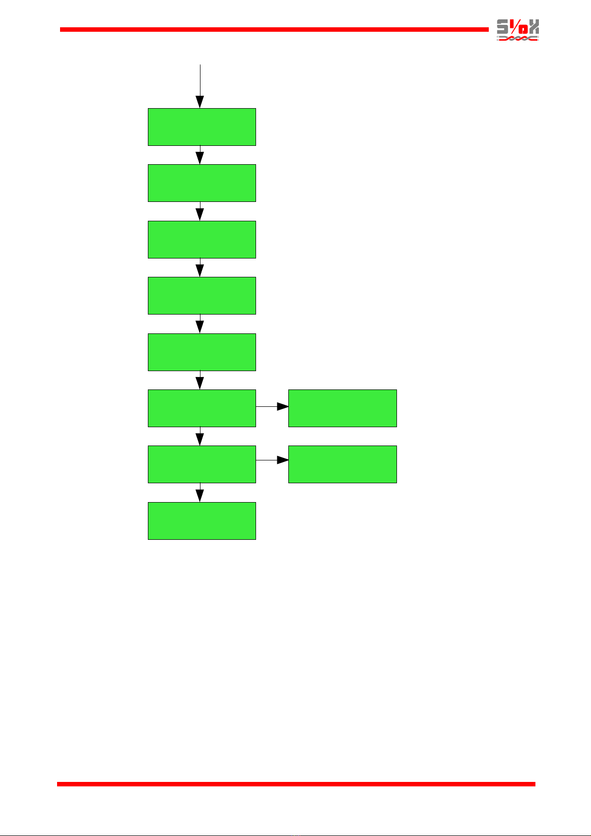
Menus
Most menus have a keyboard inactivity timeout of
3 minutes after which the display returns to the
Main menu. E.g. the Module addressing menu has
no timeout because the operation will take some
time to accomplish.
Profcon AB Page 3 www.smokecontrol.net

Profcon AB Page 4 www.smokecontrol.net
2018-02-20 15:26
SYSTEM: OK
ALARMS FIRE:OTHER
EXT.FIRE 1:1
LANGUAGE:
ENGLISH
DAMPER 2
DAMPER ERROR FC1
FIRE CELL 1
2 AP 10 DAMPERS
ALARM POINT 1
OK R
DAMPER 1
OK Ö T
FUNC. TEST ALL
DAMPERS? <ENTER>
CONFIGURATION OF
WATCHDOG Tc = 5 s
WATCHDOG
30 s (ENT=SAVE
FUNC. TEST
SETTINGS
T W T F S S I FC1
M 06:00
SETTINGS OF
CLOCK/DATE
2012-02-10 16:30
FRIDAY
SETUP RUN IND.
OPEN AT FUNC.TEST
MODULE ADDRESSING ENTER = START
GROUP:0 ADDR:1
ADDRESSING...
GROUP:0 ADDR:1
FIRE CELLS
Main menu
Only in
Service Mode
MidiSmoke menu system
Continues on next page
Only in
Service Mode
Only in
Service Mode
Only in
Service Mode
Only in
Service Mode
Only in
Service Mode

Profcon AB Page 5 www.smokecontrol.net
SIMPLE SYSTEM-
CONFIGURATION
SEARCHING...
NMBR:2 A:1 SC2
FOUND MODULES
NMBR:2 A:1 SC2
MODULE-
CONFIGURATION
CONFIGURATION FOR
ADDR:1 LP S1 S2
CHANGE PIN-CODE NEW PIN: 5555
C=ABORT
CHANGE IP-ADDRESS C=ABORT,ENTER=OK
192.168.000.234
SET TCP/IP PORT C=ABORT,ENTER=OK
PORT:01024
STATUS EXTERNAL
ALARM DI1:CLOSED
STATUS FIRE RESET
DI2:OPEN
STATUS NIGHT MODE
DI3:OPEN
Only in Service
Mode. Not when
using SmokeEdit
From previous page
Only in
Service Mode
Only in
Service Mode
Only in
Service Mode
Only in
Service Mode
Only in
Service Mode
Only in
Service Mode
Only in
Service Mode
Only in Service
Mode. Not when
using SmokeEdit
Continues on next page
CHANGE IP-GATEWAY
SET SUBNET MASK
C=ABORT,ENTER=OK
192.168.000.001
C=ABORT,ENTER=OK
255.255.255.000
Only in
Service Mode
Only in
Service Mode
FUNCTION TEST
START DELAY
SET FUNCTION TEST
START DELAY 060 s
Profcon AB Page 6 www.smokecontrol.net
SUM ALARMS
OUTPUT DO1:OPEN
FIRE ALARM
OUTPUT DO2:CLOSED
SD SERVICE
OUTPUT DO3:CLOSED
RUN INDICATOR
OUTPUT DO4:CLOSED
SET SERVICE MODE
TIMEOUT
SET SIOX REPEATS
EX2 VERSION
EX2 v1.61
From previous page
Only in
Service Mode
Only in
Service Mode
Only in
Service Mode
Only in
Service Mode
Only in
Service Mode
Only in
Service Mode
Only in
Service Mode
STATUS FUNC.TEST
DI4:OPEN
Only in
Service Mode
SERVICE MODE
TIMEOUT INACTIVE
SIOX REPEATS:3
H:3 G:0 A:1

Main menu
OK: No alarms.
OK TEST: Functional damper test is in progress.
FIRE: One or more alarm points detected
a fire alarm or one or more alarm
points are not answering.
B-ALARM: Service alarm from a smoke detector,
damper error from a damper module or
that one or more damper modules are
not answering.
NO APP: No configuration is loaded, or halted.
Could happen if a Smoke Edit
download is aborted for some reason.
In that case just try to download again.
If a small “N” is displayed before the status text
then the system is in Night mode (dampers closed
thru activation of DI3.
If “F1” is pressed, a text is displayed showing the
name of the configuration file. If the configuration
file is customer specified, the text displayed can be
freely chosen, e.g. to display the facility name of
the installation.
Service Mode
By pressing “F2” in the main menu it is possible to
enter the Service Mode. In Service Mode
outgoing fire alarms are blocked but shown in
the display to facilitate fault tracing. Also,
dampers are opened and automatic or via DI4 re-
quested functional tests are suppressed. However,
functional tests (exercise can still be requested via
the Function test all dampers menu, external DI-
modules or thru Modbus TCP.
Unless the Service Mode is entered, only the
larms menu, Fire cells menu and Function test all
dampers menu are available.
When the work is completed it is mandatory to
remember to exit the Service Mode by pressing
key “F2” and then “C” in the main menu.
If the green OK LED is on it indicates normal
alarm free operation and that Service Mode is
not active.
From system software version .6 it is also
required that the communication watchdog be
set for the OK LED to be lit.
To enter Service Mode, press “F2” and the
following text on the display is shown:
Numbers in the pin code are changed using the
arrow keys.
When the correct pin code is entered press Enter.
Default pin code is 5555.
Reset pin code to factory default
If the PIN code has been lost there is a recovery
method: Hold down the “C” key while restarting the
module (cycling the power . When the question
“RESET PIN CODE TO 5555? ENTER=OK” is
shown, press Enter.
Change language
If the Service Mode is active and the Up arrow is
pressed in the Main menu, a menu to change the
language is displayed. Press Right arrow to toggle
the alternatives Swedish and English. Confirm by
pressing Enter.
Alarms
Shows current alarms. Press Enter to display the
alarm list. Press Down arrow to advance to the
next alarm in the list or Up arrow to return to the
previous alarm. EXT.FIRE is the DI1 Fire Alarm
input on the MIDI SMOKE 2 module. DI2 must be
activated (>1,5 s to unlatch this alarm.
Remember: ”C” backs one step in the menues
and/or aborts a command.
In system software version 1.62 a check was
introduced for a very rare error.
If the display shows “MODULE FAIL (SD ” it means
that the damper module on the address shown is
not defined as an Alarm Point but nevertheless is
in Fire status (and its dampers will be closed . The
reason for this is that the local smoke detector
input rises the alarm. Check that the resistor (2,2
kohm , which should be installed between
terminals 4 and 5 on an SC2-module is correctly
installed and that the terminal screws are
tightened.
Profcon AB Page 7 www.smokecontrol.net
ALARM FIRE:OTHERS
EXT.FIRE 1:1
2018-02-20 15:26
SYSTEM: OK
PIN: 5555
C=EXIT SERV. MODE
MODULE FAIL (SD
Address G:0 A:7

Fire cells
The fire cell above includes two alarm points and
10 dampers. The “A” in “AP” is blinking. Right/Left
arrow moves the cursor between “A” and “D”.
Pressing Up arrow will go to the next fire cell.
Pressing Down arrow will go to the previous fire
cell. Pressing Enter will show a list of the
predefined alarm points or dampers in the current
fire cell as in the examples below. Press Down
arrow or Up arrow to move between the different
alarm points or dampers.
On top is shown the name of the alarm point. The
lower line shows its status. If it is a smoke detector,
a blinking “R” will be shown at the extreme right to
indicate that a reset command can be sent by
pressing Enter.
On top is shown the name of the damper. The
lower line shows its status and end point indication
(“O” for open, “C” for closed . A blinking “T” will be
shown at the extreme right to indicate that a
function test can be run by pressing Enter.
Function test all dampers
Pressing Enter will carry out a function test on all
connected damper modules. Normally the dampers
will start with a 5 seconds interval within each fire
cell.
Watchdog (Service Mode)
This is to set up the maximum acceptable com-
munication interruption time before a module
enters fire alarm mode closing its local damper(s
and opening its local alarm relay. Tc is a value
describing the current cycle time for the system.
The selected watchdog time must be higher than
Tc. The time can be set to 0 s, 30 s, 40 s, 50 s up
to 90 s in 10 s increments. If damper modules
have been replaced in the system it is
important that the watchdog configuration is
repeated to initialize the new modules.
Up/Down arrow adjusts the value. Enter sends the
value to all modules. If the value is set to zero the
function is deactivated. This is useful during com-
missioning to stop dampers from closing unex-
pectedly due to disruptions in the execution of the
MIDI SMOKE 2 controller. A cyclically displayed
warning text “W TCHDOG IN CTIVE” will be
shown in the main menu (not if Service Mode is
active to indicate this condition. At a convenient
point during the commissioning the watchdog
should be properly set so that dampers will
close if the communication breaks down.
Functional test setup (Service Mode)
To configure the functional test setup, press the
Enter key.
The lower line shows which days to run a test of
the dampers in the current fire cell and the time of
day. Use the Left/Right arrows to change the day
position and also to enter the hours/minutes field.
Use the Up/Down arrows to pull the day letters to
the upper or lower line and to increase/decrease
the time. If no weekdays are selected for damper
test the modules will be configured to do function
tests on their own at 48 hours interval (time
counting starts when they are powered up . If the
“I” alternative is selected and no weekdays are
selected it means that the 48 hours interval in the
modules are inhibited. This choice is typically used
if the exercise should only be controlled by digital
inputs or thru Modbus TCP.
Press Enter when ready or “C” to exit without modi-
fications.
If there are more fire cells to configure the next one
will be shown in the order they appear in the
configuration file.
Default time for functional test is monday 06.00
hrs.
Profcon AB Page 8 www.smokecontrol.net
FIRE CELL 1
2 AP 10 DAMPERS
DAMPER ST2_1
OK O T
ALARM POINT 1
OK R
FUNC. TEST ALL
DAMPERS? <ENTER>
WATCHDOG SETUP
Tc = 3s
WATCHDOG
30 s (ENT=SAVE
M T T F S S I FC1
O 06:00
FUNC.TEST
SETTINGS

Setting up date/time (Service Mode)
The value to change is blinking. Right/Left arrows
moves the cursor between year, month, day etc.
Up/Down arrows increases/decreases the value.
Press Enter when done. Press “C” key to exit
without modifications.
Run indication relay output/Operational mode
(Service Mode)
There are 15 possible functions for the run
indication relay output DO4. Change mode with
Right / Left arrow:
OPEN AT FUNC.TEST – relay opens as long as at
least one module is performing a function test.
OPEN AT NIGHT – relay opens if system is in night
mode.
NIGHT+FUNC.TEST – relay opens if system is in
night mode or a function test is performed.
OPEN AT SUM ALARM – relay opens if there is
any damper error or communication error in the
system.
SUMALARM+FUNCTEST – relay opens if there is
any damper error or communication error in the
system or a function test is performed.
SUMALARM+NIGHT - relay opens if there is any
damper error or communication error or if system
is in night mode.
SUM+NIGHT+F.TEST – relay opens if there is any
damper or communication error, or if the system is
in night mode or a function test is being performed.
OPEN AT FIRE – relay opens in case of fire alarm.
FIRE+FUNC.TEST – relay opens in case of a fire
alarm or a function test is being performed.
FIRE+NIGHT – relay opens if case of a fire alarm
or if system is in night mode.
FIRE+NIGHT+F.TEST - relay opens in case of a
fire alarm, or if the system is in night mode or a
function test is being performed.
FIRE+SUMALARM - relay opens if there is a fire
alarm, a damper error or a communication error in
the system.
FIRE+SUM+F.TEST - relay opens in case of a fire
alarm or if there is a damper or communication
error in the system or a function test is being per-
formed.
FIRE+SUM+NIGHT - relay opens in case of a fire
alarm, a damper or communication error in the
system or if the system is in night mode.
FIRE+SUM+NIGHT+FT - relay opens in case of a
fire alarm, a damper or communication error in the
system, or if system is in night mode or a function
test is being performed.
Module addressing (Service Mode)
This setup menu is used for addressing damper
control modules. Every module in the system
requires a unique address. The address consists of
a Group address and a Module address. The
Group address is either zero which is used to
address the first 1-59 damper modules or it could
be 61, 62 or 63 that defines three possible
addressing subgroups (only available if SMOKE
EDIT is used). Each group can handle up to 59
damper modules (less if other modules are used
as well .
Please note that if digital I/O-modules are used, for
example S27, they should be addressed from
address 59 and downwards. This means that
correspondingly fewer damper modules can be
installed on group zero.
All modules are at Group address 0 and Module
address 1 when they are delivered from factory.
Press Enter to select Module addressing menu.
The modules should be addressed in the interval
1-59, that's why the addressing starts at 1. If
another start address is desired, just change it by
pressing the Up/Down arrows to increase/decrease
and Left/Right arrows to move between Group and
Module address.
When Enter is pressed the MIDI SMOKE 2 starts
to send addressing commands. All damper control
modules LEDs will start to flash (3 fast on/off . By
pressing the test button on a module it accepts the
address sent by MIDI SMOKE 2. The address in
the display now increments to the next address
and the next module in order can be addressed.
Note that no automatic wrap occurs to next Group
address when Module address 59 has been
passed. It will stay at address 59. If sub-buses are
used, restart the command and increase the
Group address to the desired Group address (61,
62, 63 . Please note that pressing Down arrow is a
quick way to reach the high Group address
numbers (0->63->62->61 . Adjust the Module
address to the desired start address before
pressing Enter to start the transmission of the
addressing commands.
Apply a distinct press on the buttons to avoid
double-activations which otherwise will result
in an address increment and a wrong address
Profcon AB Page 9 www.smokecontrol.net
2018-02-20 16:30
WEDNESDAY
SETUP RUN IND.
OPEN ON ERROR
ENTER = START
GROUP:0 ADDR:1
MODULE ADDRESSING

for the module.
To stop addressing press the “C” key.
Simple system setup (Service Mode)
(not available when using SMOKE EDIT,
only used for simpler systems using the
“MIDISMOKE_02.cfg” and keyboard setup)
The purpose with this command is to learn how
many modules that are located on the bus. Ensure
that all modules have power and that they are
connected to the bus so they can be identified. A
check is also performed that all modules are
sequentially addressed with no missing modules
inbetween.
Activate this setup function by pressing Enter. It
will scan the SIOX bus over the address range 1-
59 and count the number of modules found.
Wait until the search is over.
This menu is useful to ensure that all modules are
communicating. Also, the type of module is shown.
FOUND – total number of found modules.
A – current address.
SC2 – module type (example .
If the number of modules found matches what
is expected, press Enter.
Now a check is performed that the modules found
are sequentially addressed from address 1 and
upwards with no missing modules between the first
and the last one. If the check fails, the command is
still active so the fault could be tracked down.
Press the Up/Down arrow to increment/decrement
the address. If no module is answering on an
address, “ERR” is displayed. “DBL” is displayed if
at least two modules are on the same address. In
this case there should be another address for
which “ERR” is displayed because that module is
wrongly addressed. If a module is missing, check
the wiring, and if necessary abort this command
with the “C” key to invoke the Module addressing
command to readdress any missing modules. Then
run the Simple system setup once again.
When the check passes, the text “OK,
CONFIGURATION FOR nn MODULES” is
displayed.
The next menu Module configuration will be
entered.
Module configuration (Service Mode)
Not available when using SMOKE EDIT,
only used for simpler systems using the
“MIDISMOKE_02.cfg” and keyboard setup.
Press Enter to select Module Configuration.
This menu shows damper control modules that are
addressed in the system. If “AP” for “Alarm Point”
is displayed then the smoke detector input is used
for triggering fire alarm. If all modules will be used
with smoke detectors then pressing F1 will activate
alarm points for all modules. Pressing F2 will have
the reverse effect to deactivate all alarm points.
The selected number of dampers at each module
is not affected. “D1” and “D2” means that both
dampers are used.
To manually activate/deactivate alarm/damper
settings use Up/Down arrow to select the address
for each module to handle. Use Right arrow to
cycle between the different alternatives which are:
One damper only
One damper + Alarm point
Two dampers
Two dampers + Alarm point
Alarm point only
Changes are instant. Exit with Enter or “C” key.
Note that if a two-damper module is used but
configured for one damper, the damper must be
connected to channel 1. The Open and Closed
inputs for damper 2 must be jumpered i.e. be in
active state. For instance, the SC2 module should
have jumpers between terminals 24-25 and
terminals 26-27.
Factory default configuration: no Alarm Points,
one damper per module.
If “COMMERR” is displayed then no module is
answering on that address. Unless some fault has
Profcon AB Page 0 www.smokecontrol.net
CONFIGURATION FOR
ADDR:1 AP D1 D2
FOUND MODULES
FOUND:2 A:1 SC2
SIMPLE SYSTEM
SETUP
ADDRESSING...
GROUP:0 ADDR:1
SEARCHING MODULES
FOUND:2 A:1 SC2
MODULE
CONFIGURATION

occurred that prevents a module to answer, this
means that the address is not used in the system
(and not the addresses above either . Check that
the previous address was the highest in use.
Change PIN code (Service Mode)
Press Enter to change the PIN code.
Numbers in the pin code are changed with the
arrow keys. When the new pin code has been
chosen, press Enter to confirm and store the new
code.
If the PIN code is lost, see Reset pin code to
factory default for advice.
Change IP-address (Service Mode)
If the unit will be connected to Ethernet, the IP-
address may have to be changed from the default
192.168.0.234.
Press Enter to change the IP-address.
Numbers in the IP-address are changed with the
arrows. When the new address has been chosen,
press Enter to confirm and store the new address.
The module must be restarted (power off/on) to
effectuate the change.
Please note: if a direct connection between the
MIDI SMOKE 2 and a PC (Windows is desired, it
will be necessary that the IP-address for the PC
and the MIDI SMOKE 2 shares the same network
address space. Typically this means that the first
three fields in the IP-address must be identical.
The last field must differ.
Either change the IP-address for the PC or the
MIDI SMOKE 2.
Change IP-gateway address (Service Mode)
Introduced in firmware 1.40
If the unit will be connected to Ethernet, the IP-
gateway address can be changed to match the
current network.
Press Enter to change the IP-gateway address.
Numbers in the IP-gateway address are changed
with the arrows. When the new address has been
chosen, press Enter to confirm and store the new
address.
The module must be restarted (power off/on) to
effectuate the change.
Change subnet mask (Service Mode)
Introduced in firmware 1.60
If the unit will be connected to Ethernet, the Subnet
Mask can be changed to match the current
network. Factory default setting is 255.255.255.0.
Press Enter to change the Subnet Mask.
Numbers in the Subnet Mask are changed with the
arrows. When the new address has been chosen,
press Enter to confirm and store the new address.
The module must be restarted (power off/on) to
effectuate the change.
Change port number for TCP/IP (Service Mode)
Press Enter to change the port number.
This port is used for SioxNet TCP/IP
communications used by SioxTools and
Profcon AB Page www.smokecontrol.net
CHANGE PIN CODE
NEW PIN: 5555
C=ABORT
CHANGE IP-ADDRESS
C=ABORT,ENTER=OK
192.168.000.234
CHANGE TCP/IP PORT
C=ABORT,ENTER=OK
PORT:01024
CHANGE IP-GATEWAY
C=ABORT,ENTER=OK
192.168.000.001
SET SUBNET MASK
C=ABORT,ENTER=OK
255.255.255.000

VisualSetup forms but not for Modbus TCP/IP
communications. Modbus TCP/IP communications
should use the standard Modbus TCP/IP port 502.
Please note that normally there is no need to
change the port number. Standard port number is
1024. Lower numbers should not be used. Highest
available is 65535.
The port number is changed with the arrow keys.
When the new number has been chosen, press
Enter to confirm and store the new port number.
The module must be restarted (power off/on) to
effectuate the change.
Set exercise start delay (Service Mode)
Introduced in firmware 1.60
When damper function test (exercise is requested
either thru digital inputs, real time clock controlled
or via the “FUNC. TEST ALL DAMPERS” menu
then a configurable delay (0-500 seconds can be
set to stop fans that are controlled by exercise
status outputs before the actual exercise starts.
For instance, if relay output DO4 is configured to
open during exercise and the time is set to 60
seconds then the relay output will open 60 seconds
before actual exercise starts.
Press Enter to change the time.
Up arrow increases the time in 10 seconds
increments. Down arrow resets the time to zero.
Press Enter to confirm or “C” to exit without any
change.
Show digital input status (Service Mode)
For each of the four digital inputs DI1-DI4 there is a
menu showing current status to aid in fault tracing.
Show digital output status (Service Mode)
For each of the four digital outputs DO1-DO4 there
is a menu showing current status to aid in fault
tracing. To toggle the output status press Left key
or Right key. Please note that as long as these
menues are active, MIDI SMOKE 2 is not able to
control the output statuses. Also be aware that
reversing the output status may affect connected
systems, i.e. a fire alarm could be generated.
Press “C” or Enter to exit command.
Set service mode timeout (Service Mode)
The time for automatic exit from Service Mode
back to normal operation can be set between 1 -
72 hours or be inactivated (no automatic exit .
Factory default is no automatic exit.
If a unit is mistakenly forgotten in Service Mode
then it will return back to normal operation after the
time expires. Please note that pressing any key on
the keyboard will reinit the timeout time.
Press Enter to change the timeout.
Profcon AB Page 2 www.smokecontrol.net
STATUS EXTERNAL
ALARM DI1:CLOSED
STATUS FIRE RESET
DI2:OPEN
STATUS NIGHT MODE
DI3:OPEN
STATUS FUNC.TEST
DI4:OPEN
SUM ALARMS
OUTPUT DO1:CLOSED
FIRE ALARM
OUTPUT DO2:CLOSED
SD SERVICE
OUTPUT DO3:CLOSED
RUN INDICATOR
OUTPUT DO4:CLOSED
SET SERVICE MODE
TIMEOUT
EXERCISE START
DELAY
SET EXERCISE
DELAY 060 s

Pressing Down arrow inactivates the automatic exit
function.
Pressing Up arrow increases the time with 1 hour
for each keypress up to a maximum of 72 hours.
Press “C” to exit the command and keep the old
setting.
Press Enter to save the new setting and exit the
command.
Set SIOX Repeats (Service Mode)
The functions in this menu are only of interest if the
system experiences communication problems.
The number of communication retries (repeats
before a communication is deemed unsuccessful
can be set within the interval 3-30. Normally the
number is 3, which is the factory default. To assist
in troubleshooting the number of repeats can be
increased by pressing Up arrow or decreased by
pressing Down arrow.
In the example above number of repeats have
been increased to 10. For the lower line “H:5”
(“H”=Highest means that the module on
Groupaddress 0 and Module address 8 has
needed at most 5 retries. It is the first module with
most retries that is shown. If the module did not
answer at all then “H:10” would be shown because
all retries had been expended. To reset the
“Highest”-indication and restart a new
measurement, press Right arrow. Fault tracing can
then primarily be directed against the bus section
where the module with most communication
failures is located.
Show system program version (Service Mode)
Shows the version of the system program
(firmware .
Press “C” or Enter to exit the command.
Step-by-Step instructions to commission a
system using MIDISMOKE_02.cfg
Please note: these instructions are not valid when
the SMOKE EDIT software is used. See next
section for information about systems using
SMOKE EDIT for configuration.
The MIDI SMOKE 2 is normally preloaded with a
configuration file (“MIDISMOKE_02.cfg” intended
for simpler systems where the key pad is used for
setup. These systems support up to a maximum of
59 damper modules (addressed from 1-59 in a
single fire cell. Single or dual damper modules
can be used.
Assuming that the electrical installation is ready
with all damper units installed, there are a few
steps necessary to get the system up and running.
For more information about specific menu
functions, please refer to the corresponding
section in this document.
Step : Addressing the modules
Please note: if a PC is connected to the MIDI
SMOKE 2 module, the PC-based software
SioxTools could be used as an alternative to
address the modules.
Enter the Service Mode and continue down to the
MODULE DDRESSING menu.
Press Enter to start the addressing operation and
note that it starts at Group Address=0 and Station
Address=1 which is the address for the first
module. The address range for the modules in the
system will be in the range 1 – 59 depending on
how many modules that actually are installed.
Group Address should always be 0.
When the display shows...
...it means that addressing commands are sent to
the modules. Their LEDs are flashing red in short
bursts while they are receiving addressing
commands.
Now the test buttons on the alarm/damper modules
can be pressed one after the other in the sequence
that matches the desired addressing of the
modules. When the first module's test button is
pressed it will receive address 1. Continue with the
next module that should be at address 2, and so
on. When the test button is pressed, five fast
flashes on the module's LED will indicate that it
received the address and the next module in order
can be handled.
Profcon AB Page 3 www.smokecontrol.net
ADDRESSING
GROUP:0 ADDR:1
EX2 VERSION:
EX2 ver 1.61
SERVICE MODE
TIMEOUT 1 h
SIOX REPEATS:10
H:5 G:0 A:8

If by mistake a test button is pressed more than
once so the address has incremented beyond the
next module's intended address, this can be
corrected by pressing the Down arrow on the MIDI
SMOKE 2 to decrease the address. Then return to
where the module is located and repeat the
addressing operation by pressing the test button
again. Continue to the next module in the
sequence.
When all modules are handled, return to the MIDI
SMOKE 2 unit and check at the display that the
next module it is trying to address is one address
above the last used address in the system. This
means that the operation was successful.
Press the “C” key to back out of the addressing
operation and enter the main MODULE
DDRESSING menu.
Step 2: Perform Simple System Setup
Press Down arrow to display the SIMPLE
SYSTEM SETUP menu.
Press Enter to start the setup process. The
objective it to find the number of damper modules
used in the system.
Step 3: Setup dampers and alarm points
For each module a setup must be performed to tell
the system if it includes an alarm point and/or how
many dampers are connected to it.
To accomplish this, refer to the previous section
Module configuration.
Step 4: System test
At this point the MIDI SMOKE 2 unit is
communicating with the damper modules in the
system and status will now be updated. If there are
alarms use the larm menu and Fire cells menu to
get information about what and where the problem
is.
A Function test all dampers could be attempted to
check that all dampers can manage a close/open
operation.
Step 5: Setup the run indication relay output
The Run indication relay output (DO4 is a
normally closed relay which opens at one of 15
different combinations of events which are a mix of
sum alarm, night mode, functional test and fire
alarm.
If the Run indication relay output (DO4 will be
used it has to be configured for the desired
combination of events, otherwise go to the next
step.
See Run indication relay output menu description.
Step 6: Set RTC
The real-time clock is used for automatic functional
test scheduling.
See Setting up date/time menu description.
Step 7: Functional test settings
Functional tests can be requested in three different
ways:
1. By an activation (>1,5 second of DI4.
2. At specific day(s at a specific time.
3. At 48 hours intervals handled by the modules.
Alternative 3 is valid if no day/time or “I” is
specified.
Please note that an activation of DI4 will always
request a functional test sequence unless Service
Mode is active.
See Functional tests menu description.
Step 8: System test
Check the display for possible errors and correct
them.
If external systems are connected to the digital
inputs and relay outputs their operation can be
checked now.
See Show digital input status and Show digital
output status menu descriptions.
Step 9: Change the PIN code
If required, change the Pin Code in order to avoid
inadvertent access to the system setup. Keep a
note of the new one in a safe place.
See Change PIN code menu description.
Step 0: Activate watchdog
Enter the Watchdog menu and set the watchdog
timeout.
See Watchdog menu description.
Step : Set time for automatic exit from
Service Mode
If desirable, the time for automatic exit from
Service Mode can be set. Factory default is that
automatic exit is inactivated. Time can be set
between 1 – 72 hours.
See Set Service mode timeout menu description.
Step 2: Let the system enter normal operation
Exit the Service Mode by pressing “F2” och ”C” in
the main menut to let the system run in normal
operational mode.
Fire alarms will now be distributed thru DO2 to any
external systems.
Profcon AB Page 4 www.smokecontrol.net

The green OK LED should be on to indicate that
the system is operating normal and error free and
that Service Mode is not active any more.
If the communication watchdog has not been
activated then the display will flash
”WATCHDOG INACTI E!” in the main menu.
Introduced in software version .6 the green
OK LED will be off during normal operation
(unit not in Service Mode) if the communication
watchdog has not been activated. Also, the
ERROR LED will flash at the same rate as the
warning text in the main menu.
Note that the flashing has higher priority than other
errors that otherwise would give a constant
activation of the ERROR LED.
Remedy this by activating the communication
watchdog.
This concludes the setup and configuration task.
Step-by-Step instructions to commission a
system using SMOKE EDIT
Assuming that the electrical installation is ready
with all damper units installed, there are a few
steps necessary to get the system up and running.
It is also assumed that a SMOKE EDIT project has
been created that can be compiled error free.
For more information about specific menu
functions, please refer to the corresponding
section in this document.
Step : Addressing the modules
Please note: if a PC is connected to the MIDI
SMOKE 2 module, the PC-based software
SioxTools could be used as an alternative to
address the modules.
Enter the Service Mode and continue down to the
MODULE DDRESSING menu. Press Enter to
start the addressing operation. Note that it starts at
Group address=0 and Station address=1. The
Station address range is 1-59 depending on how
many modules that are installed. The Group
Address is normally zero but for large systems it
could also be 61, 62 or 63. Refer to relevant
project data to find out details about the planned
module addressing in the system.
See Module ddressing menu description.
Step 2: Download the configuration file
Use SMOKE EDIT to open the project file. Check
that the project file has the MIDI SMOKE 2 IP-
address set correctly. Do this by clicking on the
”Modules” tab and then right-click on the ”Midi
Smoke” symbol and select ”Properties”. Check the
watchdog time by clicking on the ”Modules” tab
and then right-click on the ”Smoke Control” symbol
and select ”Properties”. Default time when creating
a new project is 30 seconds.
Please note that the configuration of the Run
indication relay output is done in SMOKE EDIT by
clicking on the ”Modules” tab and then right-
clicking on the ”Midi Smoke” symbol and select
”Properties”.
The configuration can also be changed by using
the key pad on the MIDI SMOKE 2, see Run
indication relay output menu description. But the
project file should be updated as well.
The functional test settings are handled in a similar
manner. Start by clicking on the ”Modules” tab. For
each fire cell right-click on the fire cell symbol and
select ”Properties”. This can also be changed by
using the key pad on the MIDI SMOKE 2 but the
project file should be updated as well. To download
a corrected project file is of course the preferred
method.
Please note that an activation of DI4 will always
request a functional test sequence unless Service
Mode is active.
Now the configuration file can be downloaded to
the MIDI SMOKE 2.
Step 3: System test
At this point the MIDI SMOKE 2 unit is
communicating with the damper modules in the
system and status will now be updated. If there are
alarms use the larm menu and Fire cells menu to
get information about what and where the trouble
is and correct it.
If external systems are connected to the digital
inputs and relay outputs their operation can be
checked now. See the earlier sections Show digital
input status and Show digital output status.
A Function test all dampers could be attempted to
check that all dampers can manage a close/open
operation.
Step 4: Set RTC
The real-time clock is used for automatic functional
test scheduling.
See Setting up date / time menu description.
Step 5: Change Pin Code
If required, change the Pin Code in order to avoid
inadvertent access to the system setup. Keep a
note of the new one in a safe place.
See Change PIN code menu description.
Profcon AB Page 5 www.smokecontrol.net

Step 6: Activate watchdog
Enter the Watchdog menu and set the watchdog
timeout. Refer to the earlier section Watchdog.
See Watchdog menu description.
Step 7: Set time for automatic exit from Service
Mode
If desirable, the time for automatic exit from
Service Mode can be set. Factory default is that
automatic exit is inactivated. Time can be set
between 1 – 72 hours.
See Set Service mode timeout menu description.
Step 8: Switch the system to normal operation
mode
Exit the Service Mode by pressing “F2” och ”C” in
the main menu to let the system run in normal
operational mode.
Fire alarms will now be distributed thru DO2 to any
external systems.
The green OK LED should be on to indicate that
the system is operating normal and error free and
that Service Mode is not active any more.
If the communication watchdog has not been
activated then the display will flash
”WATCHDOG INACTI E!” in the main menu.
Introduced in software version .6 the green
OK LED will be off if the communication
watchdog has not been activated during
normal operation (unit not in Service Mode).
Also, the ERROR LED will flash at the same
rate as the warning text in the main menu.
Note that the flashing has higher priority than other
errors that otherwise would give a constant
activation of the ERROR LED.
Remedy this by activating the communication
watchdog.
This concludes the setup and configuration task.
Installation
MIDI SMOKE 2 is intended for installation on
standard 35 mm DIN-rails conforming to EN50022
(DIN46277-3 . The unit should be located inside an
enclosure prohibiting access by unauthorized
personnel.
The module can be AC- or DC-powered. The AC
input voltage range is 12-24 V AC and the DC input
voltage range is 18-35 V DC. Power consumption
at normal operation is approximately 3,5 W.
Connection of AC power
The secondary transformer winding should be
connected between terminals 13 (G and 14 (G0 .
Connection of DC power
Connect the negative supply wire to terminal 14
and the positive supply wire to terminal 13.
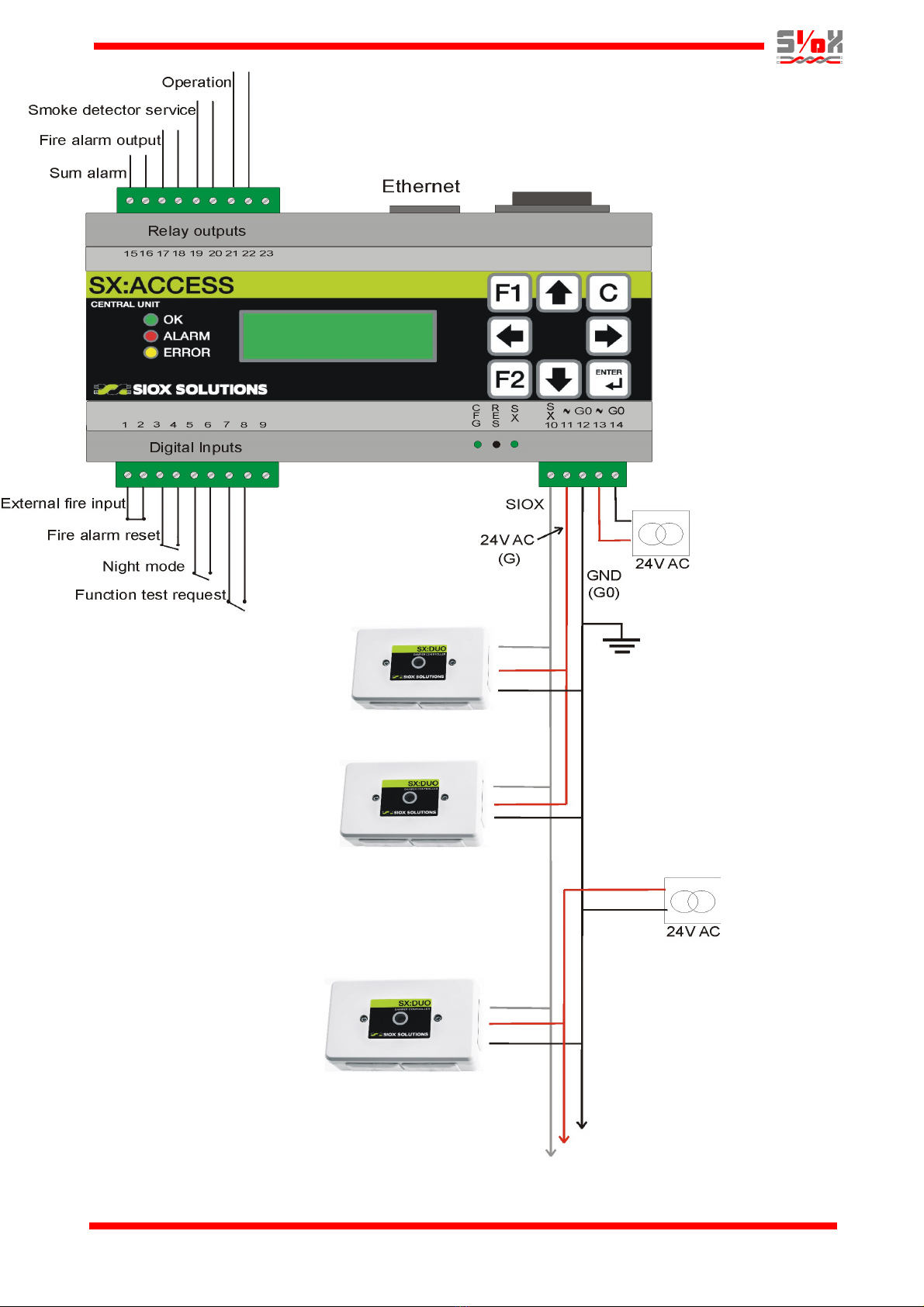
Three-wire bus
MIDI SMOKE 2 supports the three-wire concept
that is used by the Smoke Control products. The
three wires are SIOX, power (G and ground (G0 .
Terminal 10 is used for the outgoing SIOX bus.
Power to the first section of damper modules
(before another transformer handles next section
can be taken from terminal 11 (G and terminal 12
(G0 .
Please note that screw terminal 14 (incoming
power ground, G0 is internally connected to screw
terminal 12, as well as screw terminals 9 and 23 at
the I/O-connectors. Screw terminal 13 (incoming
power, G is internally connected to screw terminal
11.
For other types of modules, e.g. S45 and S27 that
must be separately powered by 24 V DC, their
SIOX bus connection should be connected
between terminal 10 (SIOX and terminal 12 (G0 .
The ground wire (G0 should always be routed
thru the whole system, only interrupted if R30
Bus Expander Modules are used that provides
galvanic isolation between bus sections.
The third wire (G is used to power the modules.
Depending on the size of the installation this wire is
usually divided into segments. Each segment has
its own power transformer and is powering a group
of damper modules.
Three-wire bus connection:
Screw terminal 10 is the SIOX bus.
Power to the damper modules comes out via screw
terminal 11 (G .
Screw terminal 12 is the power ground (G0 .
For more information about cable selection, please
refer to:
http://www.telefrang.se/download/pdf/CableSelecti
on.pdf
Grounding
To avoid that the system will electrically “float”, the
power ground wire (G0 at terminal 12 should be
connected to a grounded point nearby the MIDI
SMOKE 2 unit.
Because the ground potential between different
Profcon AB Page 6 www.smokecontrol.net

points in a large building could differ, ensure that
there are no other ground connections along the
three-wire bus/power cable in order to avoid the
risk of high ground currents which could lead to
disturbances or malfunction.
However, if R30 Bus Expanders are used that
provide galvanic isolation between the bus
sections, the outgoing AC/DC ground wire from the
R30 (secondary side should be grounded.
Digital Inputs
The four inputs are intended to be connected to
open/close switches. See page 1 for a functional
description.
Digital Outputs
There are four relay outputs on the MIDI SMOKE
2. Their breaking capacity is 1 A at 30 V AC/DC.
They are normally closed and opens during alarm
conditions. See page 1 for a functional description.
Ethernet
Ethernet is connected to the module thru the RJ-45
connector on the upper side of the module and is
used for Modbus TCP or SioxNet communi-
cations.
Loading of SMOKE EDIT configurations are also
done using the Ethernet connection.
The picture on the next page shows the electrical
connections for the MIDI SMOKE 2.
Profcon AB Page 7 www.smokecontrol.net
MidiSmoke2_ProdDescr_12en.odt 2018-05-30 /YE
Profcon AB Page 8 www.smokecontrol.net
Table of contents


