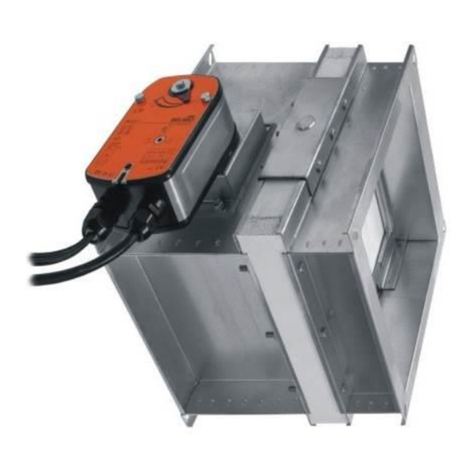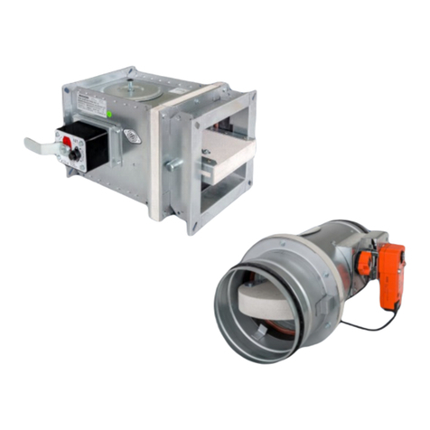
mcr WIP LD Multi-blade smoke control dampers
„MERCOR” S.A. – The company reserves the right to modify and change the document.. Version: mcr WIP LD 22.03.15.1 8/16
The mcr WIP LD damper will work properly if the isolation partition rotation axis is horizontal. The trigger
control gear may be located on the right or on the left hand side of the damper at any direction of air flow.
Before embedding/fixing, place the damper axially aligned within the partition (the wall or ceiling which
separates the fire zones) in the finished installation opening. Level the device and secure in place. Next,
actuate the damper isolation partition by hand to verify that the rotation is correct (i.e. there is no collision
with the damper casing parts, etc.). Close the damper isolation partition. Install the bracing as shown in
the figure. Carefully fill the gap between the damper casing and the wall with a proper mortar formula that
ensures proper wall and damper fire resistance, and do not let the mortar get into the damper actuation
components (i.e. the trigger control gear, the isolation partition, gaskets and stops). To do this, the fire
damper must be covered with plastic film or other suitable material and remain so until the embedding and
finishing is done. The damper must remain closed until the mortar has cured. Once the mortar has cured,
remove the temporary supports and open and close the fire damper to verify its performance. When
installing the fire damper in a panel wall, fill the space between the damper casing and the wall with mineral
wool certified for A1 fire protection rating; the mineral wool density and thickness must ensure fire
resistance no less than the fire resistance of the wall in which the fire damper is installed. The filled space
must additionally be sealed with a proper mortar or putty that has the fire resistance required for the wall.
Dla zapewnienia odporności ogniowej elementu oddzielenia ppoż. należy bezwarunkowo przestrzegać
granicy wmurowania – kołnierzem korpusu do lica ściany.
The connection of the embedded damper to the ventilation duct must be made coaxially. During the
installation of the damper, the damper body must not be damaged, and in particular, it must not be
stressed. The damper cannot constitute a "supporting element" of the duct or ventilation system on which
it is installed. It is forbidden to drill through the damper housing, screw in screws, bolts and other elements
passing through the housing to the damper's center in any place. The places used to drill through the
casing for anchoring to the fastening structure are marked (holes in the metal casing). After connecting
the ventilation duct, check the damper operation again.
5 1 23 4AA
4
1. Damper mcr WIP LD
BxH
2. Masking grille MWS
(option)
3. Cardboard wall of shaft
4. Anchor
5. Vertical fire ventilation
shaft
Damper installation in light walls (plasterboard).
5 1 2 3
4
1. Damper mcr WIP LD
BxH
2. Masking grille MWS
(option)
3. Solid wall of shaft
4. Anchor
5. Vertical fire ventilation
shaft
Damper installation in solid walls.
