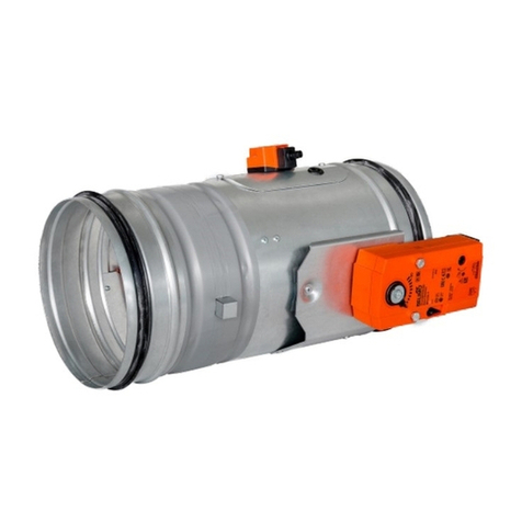
Maico BSB VC Series User manual

1
VC Damper
Installation, Operating and Maintenance Instructions
1
Health and Safety
1.1
Only competent personnel may carry out the work outlined within this document.
1.2
The wearing of appropriate Personal Protective Equipment (gloves, footwear,
safety glasses etc.) is required for safe working and as the site dictates.
1.3
Dampers may be heavy. Large dampers will require suitable lifting and
supporting equipment, with due consideration given for manual handling.
1.4
Dampers may close without warning. Do not introduce limbs/fingers in the path
of blade travel.
1.5
Where dampers are only accessible with the need for additional elevation, any
equipment used should be done so with due consideration to the Work at Height
regulations 2005 and current site rules.
1.6
All work should be carried out in accordance with HSE guidelines and regulations
and any specific local site rules.
2
Pre-Installation Notes
2.1
These instructions should be read in its entirely before installing or servicing this equipment. Improper
installation, alteration or lack of servicing/maintenance may impact on the correct product function and/or
warranty.
2.2 Ensure that all packing materials are removed, as failure to do so could result in permanent damage to
this product.
2.3 Check the damper schedules for damper size and locations within the building.
2.4 Inspect the dampers for damage and record where found.
2.5 Ensure that all dampers are installed within systems with airflows and pressures that do not exceed the
performance data within the BSB product literature.
2.6
Do not lift the damper by the blades. Dampers should be handled by the case only.
2.7 Mating ductwork connections must be square and should not deform the damper flange detail during
installation. Flanged dampers must be installed square without twisting to the mating duct flange.
2.8 Do not force the damper into position or use fixings to apply compression or stretching.
2.9 Ensure that the ductwork and damper flange or spigot are carefully matched, using the appropriate sealing material.
2.10
The damper must be protected from damp, dirt and other foreign material prior to and post installation
in readiness for hand over.
2.11
It is not recommended that dampers are painted or have a protective coating. Please refer to the BSB
sales office for advice.
2.12 Screws or fasteners must not penetrate the damper case where the linkage and blade bearings could
be impeded.
2.13 Care must be taken, that any installation material wet or dry does not come into contact with any
moving parts.
3 Equipment Required
3.1 Equipment and tools will vary dependent upon the construction element/application that the damper is being
installed within. Standard equipment that is normally used for ducted installations should suffice.
3.2 Access equipment as necessary
3.3 Temporary support equipment to retain damper in position whilst being installed.
4 Preparation for Installation
4.1 Before installation, the damper should be inspected to ensure that it has not been damaged and is in good
condition.
4.2 Check damper (label) reference, and damper size.
4.3 Check that the damper control will be accessible once installed.
4.4 Ensure damper blades are horizontal once installed unless otherwise specified and quoted for.
2
4. Flangefit
4.1 Flangefit VC series dampers are designed to match the mating ductwork flange.
4.2 Use the four corner alignment holes to position the damper using appropriate fixings.
4.3 Fix the damper flange frame to the mating ductwork flange using ductwork cleats. Where intermediate fixing bolts
are used, these should be in accordance with DW144.
4.4 Cleats are advised to be fitted as follows:
a) 200 – 300mm max centres for Pressure Class A
b) 150 – 250mm max centres for Pressure Class B and C, also allowing for a fixing within 50mm of the corner.
4.5 Ensure that the connecting ductwork is supported independently of the damper.
5. Spigotfit
5.1 Spigotfit VC series dampers are designed to be included within ductwork runs.
Appropriate sealant should be applied to the damper spigot to ensure a good seal.
The connecting ductwork should slip over the damper spigot and affixed with steel rivets.
6. Instruction for testing Damper
6.1 Once the damper has been installed, check that the blades move freely using the hand quadrant control or
gripping the extended spindle by hand. The blades should more smoothly fully open to fully closed without
using force. Where an actuator has been factory fitted, this will need to be electrically connected to allow
testing.
7. Routine Inspection, Testing and Maintenance
7.1 Refer to Health and safety procedure (section 1)
7.2 In accordance with BS 9999 Annex W.1, inspection should be undertaken annually. Local regulations/conditions
may override this with periodic Inspection being carried out more frequently where corrosive or dirty conditions prevail.
The maintenance log should be reviewed at each inspection and the frequency adjusted as required dependent
upon findings. (BSB recommend a maximum of 1 year between inspections and to start more frequently initially and
reduce frequencies only if conditions are proven to allow).
7.3 Remove access door or grille to reveal damper’s internal elements.
7.4 Visually inspect the Internal damper elements for signs of corrosion, obstruction or accumulated dirt/dust.
7.5 If there are any obstructions or if the damper blades, case sides are dirty, they need to be cleaned.
7.6 Use a soft cloth with a light application of light lubricant. (Connect Duck Oil recommended).
7.7 There should be no more than a thin film of lubricant applied. Remove all excess lubricant. It is particularly important
as excess oil will tend to collect dirt and dust which will have a negative effect on dampers remaining clean.
4.8 Replace access doors and/or grille.
4.9 Record all work that has been undertaken in the maintenance log.
4.10 It is important to record, and review maintenance frequency based on inspections and test history.

3
Width
Signature
Print Name
Signature
Print Name
5 Fault finding
Installation Check List
Damper Reference No: Damper Location
Damper Size:
ppp
mmnm
fhjnfj
Yyty
Damper Installed By: …………………………………………………………….
Final Inspection By: ……………………………………………………………..
Symptom Fault Action
Damper does not
open or close fully
Foreign object impeding blades Remove item
Build up of dirt / dust / corrosion
impeding blades
Remove / clean case & blades as
required.
Blades damaged Please contact BSB Sales Office.
April 2022
Height
Company Date
Company Date
This document is available for free download from the BSB website.
This document is subject to change without notice.
BSB Engineering Services Ltd
Tel +44 (0)1795 422609
Table of contents
Other Maico Fire And Smoke Damper manuals