Solid RocketWAVE SRF-L-8A1821 User manual

RocketWAVE™
SRF-L-8A1821
Product Manual
DEC 2021
V1.7

SOLiD RocketWAVE™ SRF-L-8A1821 Product Manual V1.7 - DEC 2021
© 2021 SOLiD, Inc. All Rights Reserved. Confidential & Proprietary. Page 2
Copyright
All rights are reserved © 2021 SOLiD. Confidential and proprietary. Information contained in this document is
company private to SOLiD and should not be modified, used, copied, reproduced or disclosed in whole or in part
without the written consent of SOLiD.
Trademark Information
No right, license, or interest to SOLiD trademarks is granted here. By using this document, you agree not to as-
sert any right, license, or interest with respect to such trademark. Other product names mentioned in this manual
are used for identification purposes only and may be trademarks or registered trademarks of their respective
companies.
Disclaimer of Liability
The contents of this document, including graphics and screenshots, are current as of the date of publication.
SOLiD reserves the right to change the contents without prior notice. In no event shall SOLiD be liable for any
damages resulting from loss of data, loss of use or loss of profits. SOLiD further disclaims any and all liability for
indirect, incidental, special, consequential or other similar damages. This disclaimer of liability applies to all prod-
ucts, publications and services during and after the warranty period.
SOLiD GmbH, December 2021
SOLiD RocketWAVE™ SRF-L-8A1821 Product Manual V1.7 - DEC 2021
© 2021 SOLiD, Inc. All Rights Reserved. Confidential & Proprietary. Page 3
Contents
General................................................................................................................ 4
1.1 Health and Safety..................................................................................................................................4
1.2 Compliance...........................................................................................................................................5
1.3 Technical Support .................................................................................................................................6
Introduction......................................................................................................... 7
2.1 System Overview ..................................................................................................................................7
Service Frequency & Bandwidth.............................................................................................7
In/Output Power & Gain..........................................................................................................7
800MHz Adaptive band combinations.....................................................................................8
2.2 Functions...............................................................................................................................................8
Repeater Interface ............................................................................................ 12
Package Configuration..................................................................................... 13
Installation......................................................................................................... 14
5.1 Donor antenna installation...................................................................................................................14
5.2 Repeater installation............................................................................................................................ 14
5.3 USIM Installation.................................................................................................................................17
Software ............................................................................................................ 18
6.1 LMT (DT_GUI) Installation ..................................................................................................................18
6.2 LMT User Interface..............................................................................................................................19
6.3 Firmware Upgrade...............................................................................................................................21
Appendix........................................................................................................... 22
7.1 General specification........................................................................................................................... 22
7.2 RF specification...................................................................................................................................22
Troubleshooting ............................................................................................... 24
SOLiD RocketWAVE™ SRF-L-8A1821 Product Manual V1.7 - DEC 2021
© 2021 SOLiD, Inc. All Rights Reserved. Confidential & Proprietary. Page 4
General
“Only qualified personnel are allowed to handle this unit. Read carefully and understand all the warning
labels attached in this user manual”. Any personnel involved in installation, operation or service of the
SOLiD repeaters must understand and comply the following:
Understand all general and regional installation and safety regulations relating to work on high voltage
installations, as well as regulations covering correct use of tools and personal protective equipment.
The power supply unit in repeaters contains dangerous voltage level, which can cause electric shock.
Switch the mains off prior to any work in such a repeater. Any local regulations are to be followed when
servicing repeaters.
The repeater cover should be (door) securely fastened in open position, e.g. bytying it up, at outdoor work
in order to prevent door from slamming due to wind causing bodily harm or damage.
Use this unit only for the purpose specified by the manufacturer. Do not carry out any modifications or fit
any spare parts which are not sold or recommended by the manufacturer. This could cause fires, electric
shock or other injuries.
Any repeater, including this repeater, will generate radio signals and thereby give rise to electromagnetic
fields that may be hazardous to the health of any person who is extensively exposed to the signals at the
immediate proximity of the repeater and the repeater antennas.
Due to power dissipation, repeater may reach a very high temperature. Do not operate this unit on or close
to flammable materials.
Do not use any solvents, chemicals, or cleaning solutions containing alcohol, ammonia, or abrasives.
For pluggable equipment, the socket-outlet shall be installed near the equipment and shall be easily ac-
cessible.
This power of this system shall be supplied through wiring installed in a normal building. If powered directly
from the mains distribution system, it shall be used additional protection, such as overvoltage protection
device.
Round terminals located on the rear of a 1.0mm2 (16AWG) or more wires using permanently connected
to earth.
CAUTIONS
This is a class B product. In domestic environment, this product may cause radio interference in which
cause the user may be required to take adequate measures.
Do NOT open except at Approved Field Force Protective Work Station
SOLiD RocketWAVE™ SRF-L-8A1821 Product Manual V1.7 - DEC 2021
© 2021 SOLiD, Inc. All Rights Reserved. Confidential & Proprietary. Page 5
Regulatory Compliance / Certifications for repeater
CE
CE Radio Equipment Directive (RED) Directive
(2014/53/EU)
RF:
ETSI EN 301 908-15 V15.1.1
ETSI EN 301 908-1 V13.1.1 (2019-11)
EN50385:2017
EMC:
ETSI EN 301-489-1 V2.2.3
ETSI EN 301 489-50 V2.3.1
Safety:
EN IEC 62368-1 :2020+A11 :2020
RoHS
2011/65/EU Amended to 2015/863/EU
REACH
EC 1907/2006 REACH Regulation
Regulatory Compliance / Certifications for power supply
CE: EN60950-1 / 62368-1
Electrostatic Discharge Immunity:
IEC61000-4-2:2008
Radiation Electromagnetic Immunity
IEC61000=4-3:2006+A1:2007+A2:2010
FAST TRANSIENT IMMUNITY
IEC61000-4-4:2004
SURGE IMMUNITY
IEC61000-4-5:2005
CONDUCTED DISTURBANCES IMMUNITY
IEC61000-4-6:2008
VOLTAGE DIPS, INTERRUPTION & VARIATIONS
IEC61000-4-11:2004
The installation to comply with European EN50385 exposure compliance requirements, the following
Power Density limits/guidelines (mW/cm2) according to ICNIRP are valid:
- 0.2 for frequencies from 10 MHz to 400 MHz
- F (MHz) / 2000 for frequencies from 400 MHz to 2 GHz
- 1 for frequencies from 2 GHz to 300 GHz
The power supply of the unit complies with Overvoltage Category II. It also complies with the surge re-
quirement according to EN 61000-4-5 (fine protection); however, installation of an additional medium
(via local supply connection) and/or coarse protection (external surge protection) is recommended de-
pending on the individual application in order to avoid damage caused by overcurrent.

SOLiD RocketWAVE™ SRF-L-8A1821 Product Manual V1.7 - DEC 2021
© 2021 SOLiD, Inc. All Rights Reserved. Confidential & Proprietary. Page 6
The repeater complies with European standard EN60950-1/EN62368-1.
To be sold exclusively to mobile operators or authorized installers - no harmonized fre-
quency bands, operation requires license. Intended use: EU and EFTA countries.
Indicates conformity with the RED directive 2014/53EU and/or RoHS directive 2011/65/EU.
Declaration of Conformity: SOLiD declares that the radio equipment type Repeater is in compliance
with Directive 2014/53/EU. The Full text of the EU declaration is available at the following website:
https://solid.com/emea/resources/product-literature/
WEEE Recycling: SOLiD complies with collection and recycling arrangements per the Waste Electrical
and Electronic Equipment (WEEE) Directive and implementing regulations. See more information at:
https://solid.com/emea/resources/product-literature/
For all technical support or product return requests, please ensure you have the SOLiD product identification and
serial number available. These can be found located on the back of the unit. The site and customer name should
also be included in all communications. All faulty units must be returned in their original or suitable protective
packaging.
Please contact SOLiD the local office or send an email via one of the following email addresses:
SOLiD EU GmbH
Gartenstr. 5, 87448 Waltenhofen, Germany

SOLiD RocketWAVE™ SRF-L-8A1821 Product Manual V1.7 - DEC 2021
© 2021 SOLiD, Inc. All Rights Reserved. Confidential & Proprietary. Page 7
Introduction
SOLiD RocketWAVE™ SRF-L-8A1821 is a compact repeater with low-power consumption supporting the three
different radio frequency bands that designed to enhance the coverage in area such home and small of-
fice(SOHO). The device supports the mobile/cellular frequency in B20(800) with adjustable filter / B3(1800) /
B1(2100) for 4G LTE and 5G NR NSA. With its compact plug & play design, installation of the device is easy and
quick. For European market, the device complies the various standard and regulation such as CE, RoHS, Fire-
load, etc. The device comes with various embedded function and feature for the stable and sustainable O&M.
The LTE modem is embedded in the device that support NMS by communicating through LTE signal. System
operation can be monitored by carrier NMS in NoC. And through this NMS feature, the device S/W can be easily
upgraded and fix when there is a case. Implementing with this features, user is able to experience the service
with good quality.
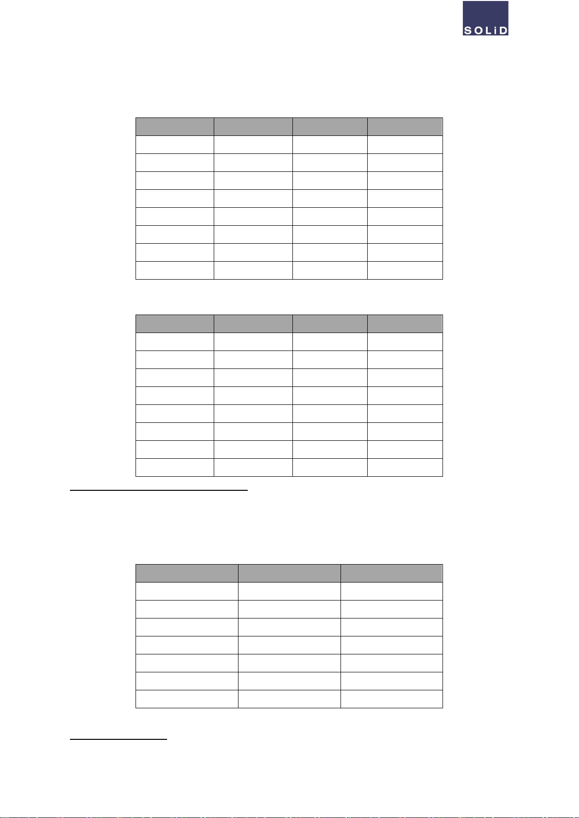
Service Frequency & Bandwidth
Frequency & Bandwidth
Downlink (TX)
Uplink (RX)
Band 20
800 MHz
Service Frequency
791 to 821 MHz
832 to 862 MHz
Bandwidth
5 / 10 MHz
5 / 10 MHz
Band 3
1800 MHz
Service Frequency
1805 to 1835 MHz
1710 to 1740 MHz
Bandwidth
30 MHz
30 MHz
Band 1
2100 MHz
Service Frequency
2150 to 2170 MHz
1960 to 1980 MHz
Bandwidth
20 MHz
20 MHz
In/Output Power & Gain
Item
Downlink (TX)
Uplink (RX)
Input Level
Gain
Output
Input Level
Gain
Output
SOLiD RocketWAVE™ SRF-L-8A1821 Product Manual V1.7 - DEC 2021
© 2021 SOLiD, Inc. All Rights Reserved. Confidential & Proprietary. Page 8
Min.
Max.
Min.
Max.
Power
Min.
Max.
Min.
Max.
Power
800MHz
-54dBm
-24dBm
34dB
64dB
+10dBm
-46dBm
-16dBm
34dB
64dB
+18dBm
1800MHz
-52dBm
-22dBm
34dB
64dB
+12dBm
-46dBm
-16dBm
34dB
64dB
+18dBm
2100MHz
-51dBm
-21dBm
34dB
64dB
+13dBm
-46dBm
-16dBm
34dB
64dB
+18dBm
800MHz Adaptive band combinations
Channel
Downlink (TX)
Uplink (RX)
Bandwidth
low
center
high
low
center
high
5 MHz
791MHz
793.5 MHz
796 MHz
832 MHz
834.5 MHz
837 MHz
796 MHz
798.5 MHz
801 MHz
837 MHz
839.5 MHz
842 MHz
801 MHz
803.5 MHz
806 MHz
842 MHz
844.5 MHz
847 MHz
806 MHz
808.5 MHz
811 MHz
847 MHz
849.5 MHz
852 MHz
811 MHz
813.5 MHz
816 MHz
852 MHz
854.5 MHz
857 MHz
816 MHz
818.5 MHz
821 MHz
857 MHz
859.5 MHz
862 MHz
10 MHz
791 MHz
796 MHz
801 MHz
832 MHz
837 MHz
842 MHz
796 MHz
801 MHz
806 MHz
837 MHz
842 MHz
847 MHz
801 MHz
806 MHz
811 MHz
842 MHz
847 MHz
852 MHz
806 MHz
811 MHz
816 MHz
847 MHz
852 MHz
857 MHz
811 MHz
816 MHz
821 MHz
852 MHz
857 MHz
862 MHz
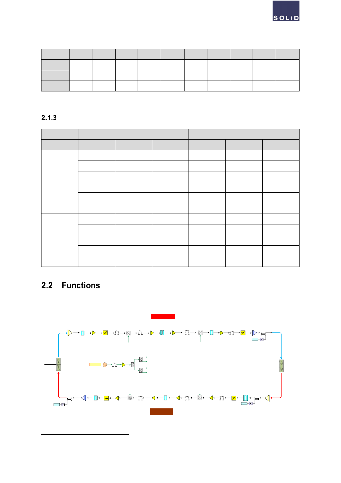
The following block diagram describes the operation principle, how the repeater works (e.g. 1.8GHz frequency
range (b3)).
Isolation Check and Gain Limitation
B3 DPX
B3 DPX
LNA
LNA
PA
AGC
ALC
AGC
ISO
PA
RF
SAW AMP PAD MIXER MIXER
AMP AMP
IF
SAW
RF
SAW PAD
DL MUX
UL MUX
RF
SAW
B3 UL Path
B3 DL Path
PAD
AMP
MIXER
AMP
IF
SAW
AMP
AMP
MIXER
RF
SAW
B3 PLL
PAD AMP
B3_PLL #1
B3_PLL #2
B3_PLL #3
B3_PLL #4
DET DET
B3_PLL #1
B3_PLL #3
B3_PLL #3
B3_PLL #4
T-PAD T-PAD
DET
AMP
T-PAD T-PAD

SOLiD RocketWAVE™ SRF-L-8A1821 Product Manual V1.7 - DEC 2021
© 2021 SOLiD, Inc. All Rights Reserved. Confidential & Proprietary. Page 9
This function is that measuring the DL isolation value between donor antenna and service antenna during the
initialization process and setting the gain value for the repeater operation. If the measured values does not satisfy
the operating condition, the repeater is shutting down. Basically the gain value for DL/UL must be maintained un-
der [DL Isolation –15dB (±3dB)]. This process is applied to all service bands. Isolation Check is done within 30
seconds and Recheck is done within 10 seconds.
When a repeater is turned on, the system performs Isolation Check 3 times. The gain value is determined by re-
ferring to the lowest value among the three measured isolation values. If any one of these measured values does
not satisfy with operating condition (= satisfy shutting down condition), the value is excluded to the reference for
the gain value. And the repeater is shutting down.
If there occurs fluctuation in output power, more than 10 dB for 10 seconds over 5 times, the repeater performs
Isolation Recheck and set gain value properly for the last measured isolation value. After 1 hour, the repeater
performs Isolation Check one more time and set the gain value again.
Once the repeater starts to operate, the system performs the Isolation Check process one more time, once a day.
During the Isolation Recheck, the repeater is not going to shut down. If the isolation oscillation occurs while the
repeater is operating in the minimum gain value, Over-output Shutdown function performs to protect the repeater
and this time, the gain value is set to the minimum value if DL/UL gain is not under [DL Isolation -15dB (±3dB)].
Repeater Shutdown?
A repeater is shutting down when following conditions:
- DL input power is under -36dBm/Total, and measured isolation value is under 60dB.
- DL input power is over -36dBm/Total, and measured isolation value is under [DL/UL Gain + 15dB].
- Measured all 3 values satisfy above conditions.
Automatic Gain Control (AGC)
This function is that controlling gain value to maintain DL output power is [user setting value ±2 dBm] when
each service band’s DL input power is within rated range. The UL Gain must be maintained [DL Gain ±2 dB]. If
the Isolation ATT value is set due to Isolation Check, the repeater can control AGC ATT within [30dB - Isolation
ATT]. The DL In/Output and DL/UL Gain value for AGC operation is described as follows.
[B20 800 MHz]
DL Input (RSSI)
DL Output
DL Gain
UL Gain
-59 dBm
5 dBm
64 dB
64 dB
-54 dBm
10 dBm
64 dB
64 dB
-49 dBm
10 dBm
59 dB
59 dB
-44 dBm
10 dBm
54 dB
54 dB
-39 dBm
10 dBm
49 dB
49 dB
-34 dBm
10 dBm
44 dB
44 dB
-29 dBm
10 dBm
39 dB
39 dB
-24 dBm
10 dBm
34 dB
34 dB
SOLiD RocketWAVE™ SRF-L-8A1821 Product Manual V1.7 - DEC 2021
© 2021 SOLiD, Inc. All Rights Reserved. Confidential & Proprietary. Page 10
[B3 1800 MHz]
DL Input (RSSI)
DL Output
DL Gain
UL Gain
-57 dBm
7 dBm
64 dB
64 dB
-52 dBm
12 dBm
64 dB
64 dB
-47 dBm
12 dBm
59 dB
59 dB
-42 dBm
12 dBm
54 dB
54 dB
-37 dBm
12 dBm
49 dB
49 dB
-32 dBm
12 dBm
44 dB
44 dB
-27 dBm
12 dBm
39 dB
39 dB
-22 dBm
12 dBm
34 dB
34 dB
[B1 2100 MHz]
DL Input (RSSI)
DL Output
DL Gain
UL Gain
-57 dBm
8 dBm
64 dB
64 dB
-51 dBm
13 dBm
64 dB
64 dB
-46 dBm
13 dBm
59 dB
59 dB
-41 dBm
13 dBm
54 dB
54 dB
-36 dBm
13 dBm
49 dB
49 dB
-31 dBm
13 dBm
44 dB
44 dB
-26 dBm
13 dBm
39 dB
39 dB
-21 dBm
13 dBm
34 dB
34 dB
Auto Level Control (ALC) for UL over-input
This function is that preventing and maintaining the signal quality degradation due to UL’s over input power satu-
ration. The attenuator is located after UL Low Noise Amplifier (LNA). The UL In/Output and UL Gain for ALC op-
eration is described as follows.
[B20 800MHz / B3 1800MHz / B1 2100MHz]
UL Input (RSSI)
UL Output
UL Gain
-46dBm
18dBm
64dB
-41dBm
18dBm
64dB
-36dBm
18dBm
59dB
-31dBm
18dBm
54dB
-26dBm
18dBm
49dB
-21dBm
18dBm
44dB
-16dBm
18dBm
39dB
ALC for UL over-output
SOLiD RocketWAVE™ SRF-L-8A1821 Product Manual V1.7 - DEC 2021
© 2021 SOLiD, Inc. All Rights Reserved. Confidential & Proprietary. Page 11
Basically, each service band’s UL Gain value is controlled by AGC. The ALC maintains UL output level is under
[Rated power ±2dB]. The attenuator used for ALC function for UL over-output is same hardware as the one used
for the ALC function for UL over-input. The attenuator for the AGC uses a different hardware from the ALC one.
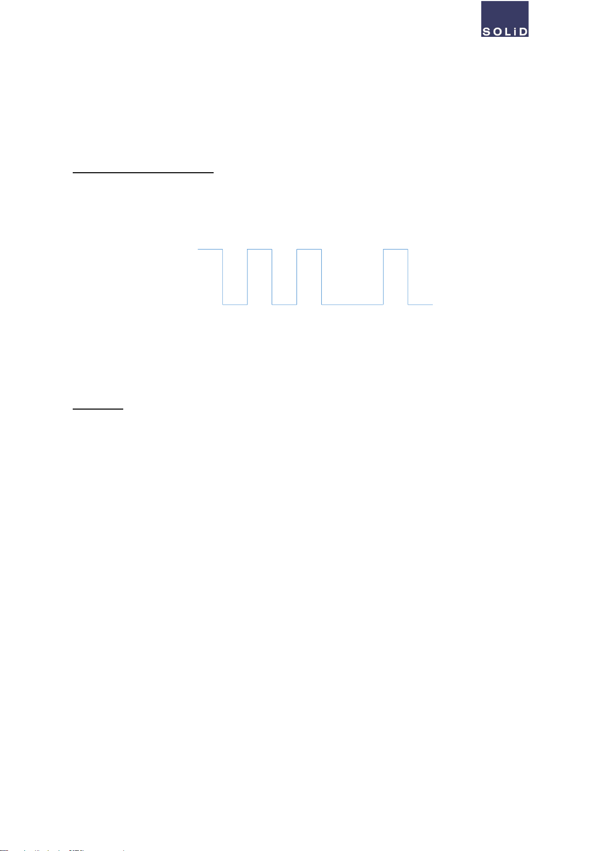
Shutdown for UL/DL over-output
This function is that automatically shutting down the service band when the DL/UL output of each service band is
over the rated. During DL Shutdown, UL Shutdown is also proceed at the same time and this is vice versa. The
operating level is [(Rated output level +2dB) ±2dB] and working algorithm is described as follows.
In ‘Check’ state, if the power level is back to normal from over-output level, the algorithm is reset. If ‘Complete
Shutdown’ occurs, a repeater is kept shut-down state, until performing Power on / Reset / Isolation Re-check.
Dying Gasp
This function is to report the alarm "Failure of the DC power supply" to the NMS using the standby power from a
connected capacitor if the DC power supply of the repeater is interrupted.
5 sec
Shutdown
Check
5 sec
5 sec 5 sec 5 sec
5 sec 30 min Complete
Shutdown
SOLiD RocketWAVE™ SRF-L-8A1821 Product Manual V1.7 - DEC 2021
© 2021 SOLiD, Inc. All Rights Reserved. Confidential & Proprietary. Page 12
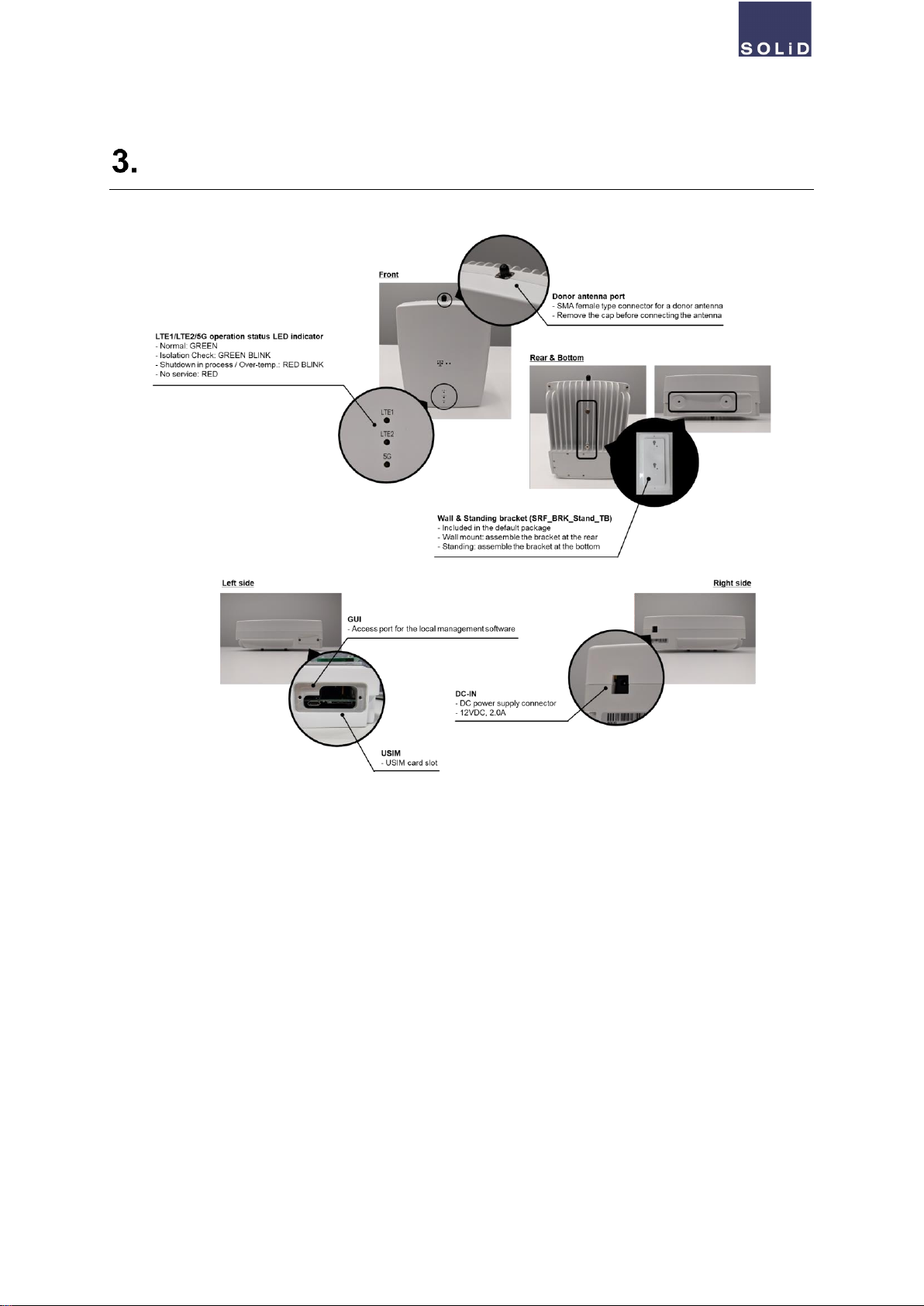
Repeater Interface
SOLiD RocketWAVE™ SRF-L-8A1821 Product Manual V1.7 - DEC 2021
© 2021 SOLiD, Inc. All Rights Reserved. Confidential & Proprietary. Page 13
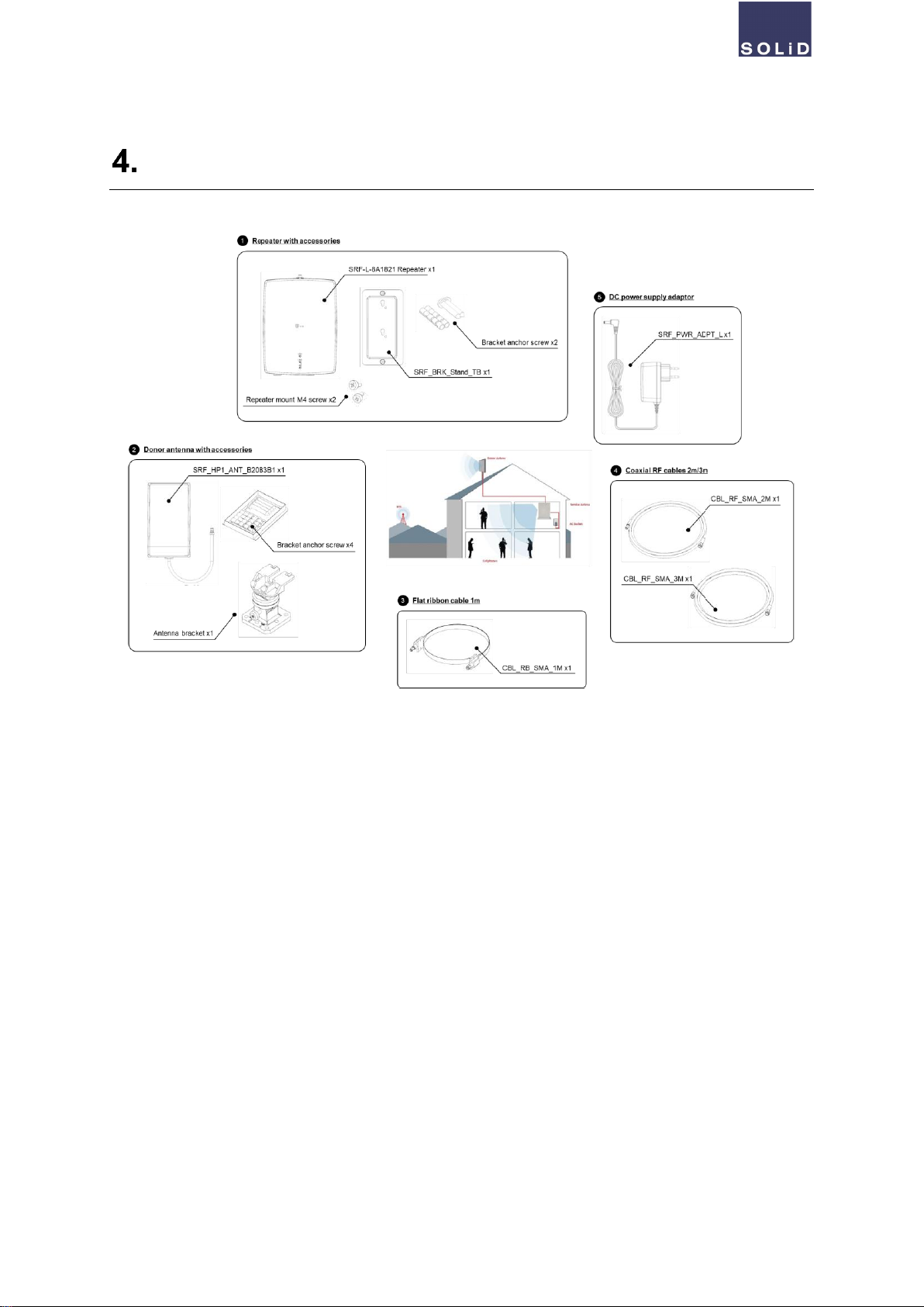
Package Configuration
SOLiD RocketWAVE™ SRF-L-8A1821 Product Manual V1.7 - DEC 2021
© 2021 SOLiD, Inc. All Rights Reserved. Confidential & Proprietary. Page 14
Installation
The general installation order is as follows:
①Install the donor antenna in the direction specified by the network operator.
(Refer to 3.2 RF specification for input power range)
②Find a proper location for a repeater.
③Install the repeater correctly as referring to the graphic described below
④Connect the repeater and the donor antenna using the supplied HF cable.
⑤Connect the DC power supply to the repeater.
⑥Check the repeater LED indicator is in green.
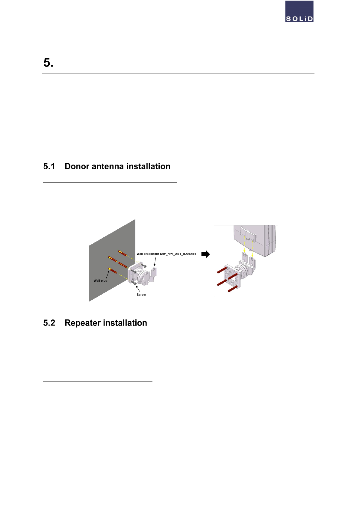
Install the donor antenna (SRF_HP1_ANT_B20B3B1)
Choose the suitable location for the antenna and make holes to secure the bracket on the wall. Assemble the
antenna to the bracket on the wall. Refer to the graphic below.
There are two ways to install the repeater. The bracket supports both mounting on the wall and standing on the
table. Depending on installation type, the installation order may be different. Choose the suitable one and follow
the orders as described below:
A. Install the repeater - Wall mounting type
Find suitable location to place bracket that is enclosed with the repeater in the package.

SOLiD RocketWAVE™ SRF-L-8A1821 Product Manual V1.7 - DEC 2021
© 2021 SOLiD, Inc. All Rights Reserved. Confidential & Proprietary. Page 15
B. Install the repeater - Table standing type
Find suitable location to place the bracket that is enclosed with the repeater in the package.

SOLiD RocketWAVE™ SRF-L-8A1821 Product Manual V1.7 - DEC 2021
© 2021 SOLiD, Inc. All Rights Reserved. Confidential & Proprietary. Page 16
C. Clearance
When placing the repeater, it requires the minimum space to keep distance from another.
SOLiD RocketWAVE™ SRF-L-8A1821 Product Manual V1.7 - DEC 2021
© 2021 SOLiD, Inc. All Rights Reserved. Confidential & Proprietary. Page 17
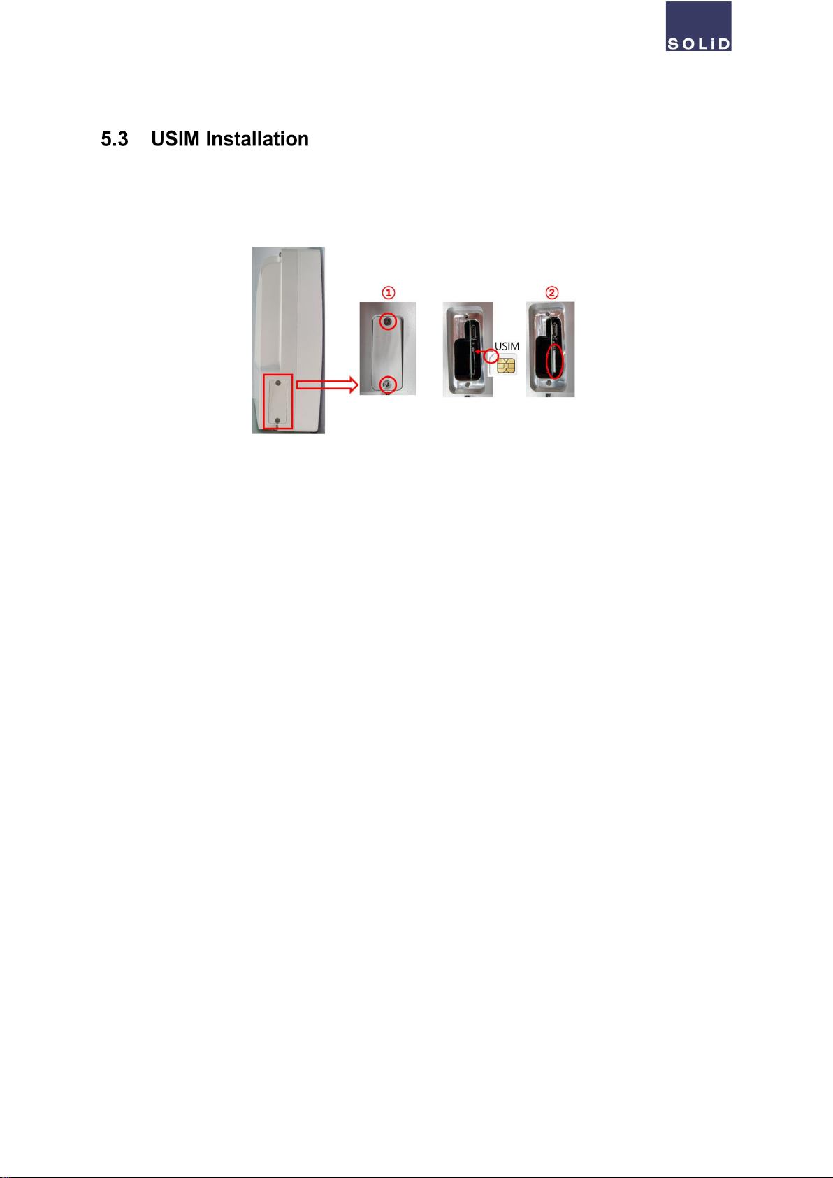
①Remove the cover to the USIM slot on the left side by loosening the screw on the lower left corner of
the repeater.
②Insert a USIM card into the slot as described as below pictures.
To remove the USIM card, push the inserted card.

SOLiD RocketWAVE™ SRF-L-8A1821 Product Manual V1.7 - DEC 2021
© 2021 SOLiD, Inc. All Rights Reserved. Confidential & Proprietary. Page 18
Software
SOLiD provides a LMT tool for a repeater to monitor its status and configure its settings. The installation process
may be different depending on the environment of the PC.
A. Install LMT
1. Run the installation file and follow the instruction to finish the installation.
2. Click [DT_GUI] icon on the desktop.
B. Run LMT (DT_GUI)
1. When DT _GUI runs, it asks to login. Enter ‘admin’ for initial password and click [Login] button.
2. When the login is successful, a repeater model selection popup appears. When the popup appears, check
[Auto Select]. If you want to select repeater model manually, uncheck [Auto Select] and then select SRF-L-
8A1821 on the list.
3. Click [Serial] button and click [Auto]. When the connection port appears on the right, then click [Connect] but-
ton to access to the repeater.

SOLiD RocketWAVE™ SRF-L-8A1821 Product Manual V1.7 - DEC 2021
© 2021 SOLiD, Inc. All Rights Reserved. Confidential & Proprietary. Page 19
No
Description
①
Repeater model name
SOLiD RocketWAVE™ SRF-L-8A1821 Product Manual V1.7 - DEC 2021
© 2021 SOLiD, Inc. All Rights Reserved. Confidential & Proprietary. Page 20
②
Connection status
③
Repeater modem information
④
Main display and control panel for a repeater information or status and configuration
No
Description
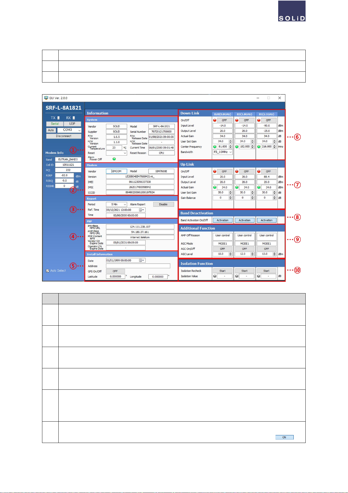
①
Displays the general information of the repeater, such as the manufacturer information, firmware ver-
sion, temperature, current time and etc.
②
Displays the modem information of the repeater, such as the manufacturer informatinon, model name,
version, and USIM related information like IMEI, IMSI and ICCID.
③
Provides user controllable panel for the reporting function of the repeater status. Available to setup re-
porting period and time, and reference time. Also provides reporting on and off button.
④
Displays the information of the repeater’s Plug and Play function. When the repeater is connected to
the upper layer (NMS), the IP addresses, APN, and certificate information appears.
⑤
Provides user controllable panel for the repeater installation information. Setup the date installed, the
location of the repeater and also GPS on and off are available. When the GPS is ON, the latitude and
longitude information appear.
⑥
Displays each band’s Downlink signal information such as the in/output signal strength and current
Gain values. Also the AMP of each band can be on and off using the button. If the button is ,
Table of contents
Popular Industrial Equipment manuals by other brands
Chevron
Chevron Performance Pipe DriscoPlex 6500 Heat Fusion Joining Procedures And Qualification Guide

Eaton
Eaton CEAG Style 21011 LED CG-S Mounting and operating instructions

ABB
ABB HT601701 Operation manual

CAMION
CAMION ICE MASTER E Series owner's manual

Metallkraft
Metallkraft HLS 85 S operating instructions

Idex
Idex KNIGHT SINK MATE PLUS instruction manual

NuAire
NuAire BPS H-AT installation manual

BrakeBuddy
BrakeBuddy SELECT 3 39524 instruction manual

Mitek
Mitek MatchPoint PLANX installation manual

Rath
Rath RGD Series Installation & operating manual

R.V.R. Elettronica
R.V.R. Elettronica PTX30 UHT/S3 user manual

Siemens
Siemens SIRIUS 3RF24 BB Series operating instructions


