TEDA KT14000 User manual
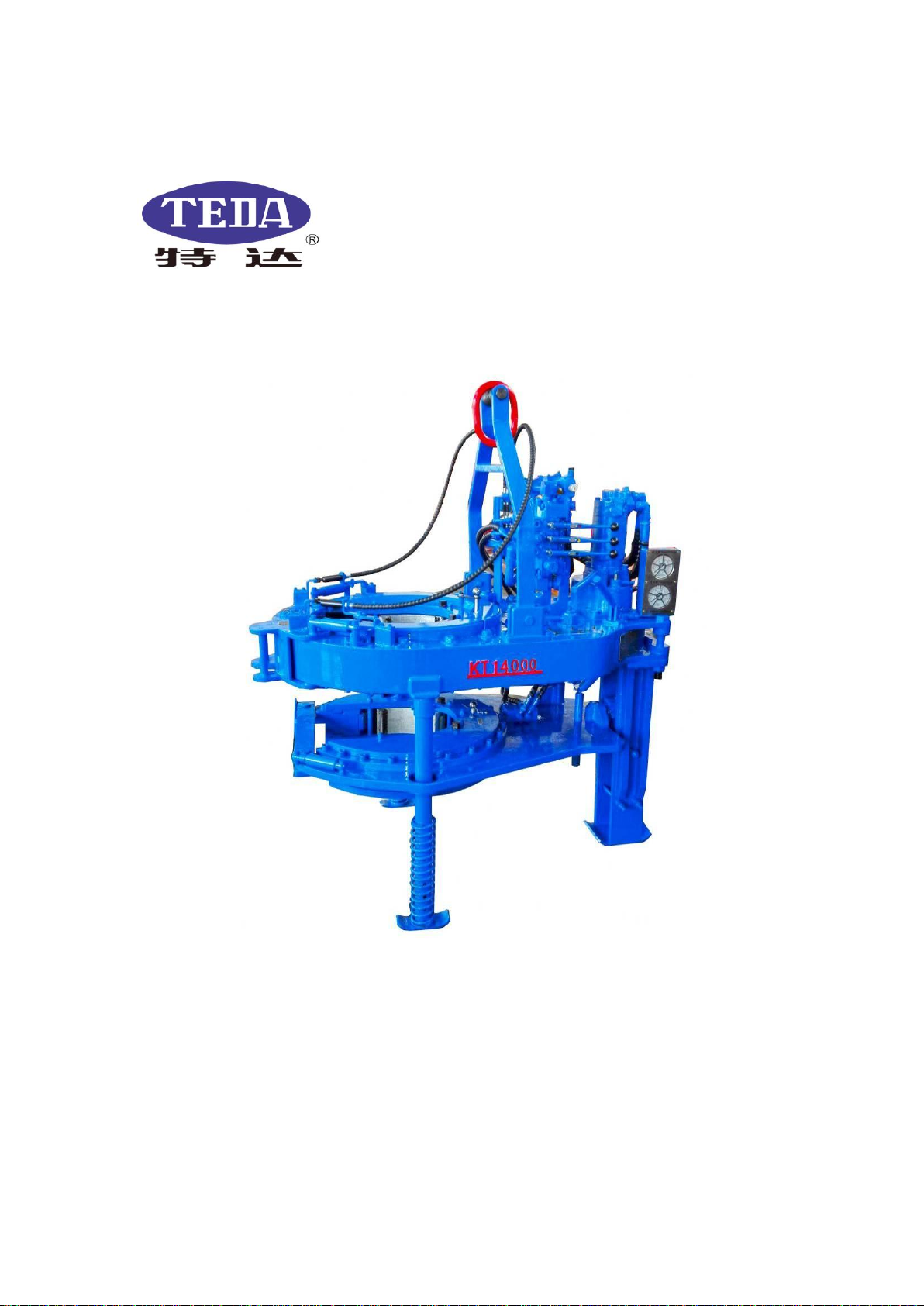
MODEL KT14 000
CASING POWER TONG
Ver 2017
Yancheng Teda Drilling and Production
Equipment Co., Ltd.


Safety Instruction
●Operators must read and know this manual well.
●Operators must wear work uniform, safety shoes, safety helmet, safety gloves, etc.
●Tie the back guy according to the instruction. Don’t tie it in the wrong direction.
●Operation at the side of tong body opening.
●Don’t touch the running parts with hands when the tong is running.
●Keep sundries out of the working area.
●The pump should be off or the hydraulic tong power shut down as maintaining or hanging
the jaw plates, die seats or tong dies.
●Over-pressure and over-torque are forbidden.
●Don’t add or dismount any parts to the tong.
●Original parts made by should be used.


Model KT14000 power casing tong maintenance and operation manual
YANCHENG TEDA DRILLING & PRODUCTION EQUIPMENT CO.,LTD
1
1.Summary
KT14000 Casing Power Tong is used to make up and break out for casing operation in oil fields. It has
greatly reduced the labor of worker, enhanced connection quality of thread and diminished accidents in
inappropriate casing operation. The power tong has the following features as well:
Features :
1.1.Opening type, convenient and prompt to enter and slide off the working position, with an integral tong
head of great strength and rigidity.
1.2.Double swing head jaws, convenient to assemble and disassemble.
1.3.Brake belt assembly, easy to operate and convenient to maintain and replace.
1.4.Four-gear rotation is adopted for large speed regulation range. And the rated torque is large;
1.5.Open gear supporting structure, improving the strength and rigidity.
1.6.Wholly hydraulic mode and mechanical gear shift.
1.7.High strength steel plate used on the shell,increasing the strength. The jaws are cast with precise
technology, artistic and strong.
1.8.With hydraulic torque indicator and also installation interface, convenient to realize the computer
management.
1.9.Use safety door hydraulic safety device and have a great safety performance.
1.10.Large torque range,can meet the requirement of larger torque use.
2.Specifications
2.1 Application Range: Master tong 4″--14″
Backup tong 4″--15 1/2″
2.2 Tong head Max. speed: High gear 41 rpm
Second high gear 18 rpm
Second low gear 10 rpm
Low gear 4.5 rpm
2.3 Max. torque: High gear 5500 ft.lbs
Second high gear 12500 ft.lbs
Second low gear 22500 ft.lbs
Low gear 50000 ft.lbs
2.4 Max. pressure: 17.2 MPa / 2500 PSI
2.5 Max. flow:150 L/min(40 GPM)
2.6 Torque arm: 1006mm/ 39.6″
2.7 Overall dimension(L×W×H): Master tong 1676×1017×1190mm/66″×40″×47″
Composite tong 1676×1017×1900mm/66″×40″×7 5″
2.8 Weight Master tong 1200kg/2646lbs(including spring cast)
Composite tong 1720kg/3790lbs(including hydraulic cast)
2.9 Specification of jaw plates: Three kinds of jaws equipped with tong 7″,9 5/8″,133/8″
The others 4″,41/2″,5″,51/2″,65/8″,75/8″,85/8″,97/8″,103/4″,113/4″,135/8″,14″and151/2″(for backup tong) are
optional.

Model KT14000 power casing tong maintenance and operation manual
YANCHENG TEDA DRILLING & PRODUCTION EQUIPMENT CO.,LTD
2
3.Operation
The instructions for tongs preparing and working as following:
3.1 Jaw installation (see illustration below):
To install the jaws, remove the jaw pivot bolts from the cage plate. Plate one jaw at a time between the
upper and lower cage plates with the jaw roller pin facing upward. Align the hole in the jaw with the
matching hole in the cage plates, and insert the jaw pivot bolt.
3.2 Tong rig-up
3.2.1 Hang the tongs
(1)Fix the single pulley (with the load of 5 tons) on the bottom girder of the crown.
(2)Put the Slip wire rope (which has a diameter of not less than 5/8″) through the pulley. One end of wire
rope fastened on the bottom girder, and other end fastened on the lift bucket(master tong can choose to
use spring lift bucket, combined tong can choose to use hydraulic lift bucket).The height of power
tongs should be equal to the average height of connectors for tripping string.
3.2.2 Leveling the tong
It is necessary to level the tongs after Hang the tongs. Otherwise, it will lead to tong tooth slipping.
Front-rear leveling--it is adjusted through the left and right two horizontal bolts at the connection position
between lifting bracket and tong body of the power tongs.
Transverse leveling--it is adjusted through leveling bolts on the upper part of lifting bracket. And it may be
adjusted through turning the bolts.
3.2.3 Pipe Connection
When the power unit is not running, or the hydraulic pump is disengaged, the
hydraulic hoses may be installed to the tong. Pay attention to the oil inlet and
outlet ports before installing, oil inlet port is NPT1″, oil outlet port is NPT1
1/4″.
3.2.4 Tie the back guy
Tail rope diameter should be no less than 5/8″.One end of tail rope is fixed on
Oil inlet
Oil outlet

Model KT14000 power casing tong maintenance and operation manual
YANCHENG TEDA DRILLING & PRODUCTION EQUIPMENT CO.,LTD
3
tong tail seat. And another end is fixed on drilling platform or the derrick. Note: when tail rope is tightened,
it should be in the same level with power tongs and perpendicular to median line of tong body.
3.2.5 Refueling Torque Cylinder
Master tong: when stretched length of piston rod of tension cylinder reaches 1 1/8″(28 mm), it is necessary
to add oil.
Composite tong: when the piston of tension cylinder is retreated to the position which is 1/4″(6.35 mm)
away from cylinder end, it is necessary to add oil.
When it is necessary to add oil, remove quick connector from torque cylinder and insert it into the quick
connector which is on the oil filled equipment(Purchase Code:KT14000-323).After oil filling, connect it.
with quick connector which is on the torque meter. Then release plug on torque cylinder until the pressure
on torque meter turns to zero.
Note: Torque testing system of master tong and Torque testing assembly can be selected according to user
needs.
3.2.6 Direction control
The handle control valve controls the tong’s
rotation direction. For clockwise rotation, push the
valve handle forward, and for reverse rotation, pull
the valve handle in the opposite direction. (see Fig.
below):

Model KT14000 power casing tong maintenance and operation manual
YANCHENG TEDA DRILLING & PRODUCTION EQUIPMENT CO.,LTD
4
3.3 Operation
3.3.1 Requirements for operators
(1)The operator should know the tong structure and the properties.
(2)Be familiar with the operation of hydraulic reversing handle on power tongs:
When manual reversing valve of control master tong is pushed, large gear on master tong turns in the
making-up tong direction; when manual reversing valve of control master tong is pulled, large gear on
master tong turns in the braking-out tong direction;
When manual reversing valve of control back tong is pushed, back tong is clamped; when manual
reversing valve of control back tong is pulled, back tong is released.
(3)Be familiar with the operation of shifting handle (various gears of shifting handle are shown in Fig.
below).
(4)Adjustment of safety door clearance
The clearance between safety door buckle and latch seat on the shell may be regulated through
adjusting
turning angle of eccentric shaft for minimum clearance for normal opening of safety door.
(5)Learn operation sequence and safety requirements;
(6)Be familiar with the instrument operation.
3.3.2 Operation of power tong
(1)Learn specifications of jaw plates and Die: each specification jaw plate of master tong and backup tong
have two jaw plates, and the two are same and may be installed on the left and right. During installing
jaw plate, it is necessary to check whether Die is worn or clean. It is necessary to tighten fixation bolts
of Die.
(2)Install jaw plate and Die with corresponding size for the string.
(3) Put shifting handle of the upper and lower shifting device on the neutral position;
(4)Start hydraulic power station;
(5)When hydraulic reversing handle is pushed or pulled, rotation noise of hydraulic motor should be heard
and open gear of tong head should not rotate;
(6)When shifting handle is put on any gear and hydraulic reversing
Note: shifting should be carried out when hydraulic motor stops the rotation.

Model KT14000 power casing tong maintenance and operation manual
YANCHENG TEDA DRILLING & PRODUCTION EQUIPMENT CO.,LTD
5
3.3.3 Working Process
(1)Align the opening of large gear of tong head with the opening of jaw plate bracket.
(2)Insert reversing pin into making-up and breaking-out hole according to the operation requirements and
adjust the tight degree of braking staple.
(3)Align the opening of large gear of tong head with the shell opening.
(4)Pull out safety door, push power tongs toward the string to allow the string to be on the central position
of tong head and close safety door.
(5)Making-up operation regulation:
a.Open the safety door, push the tong’s opening to the casing pipe;
b.Close the safety door completely;
c.Put the reversing shaft into the reversing hole(shown in the Fig. below);
Shift transmission into high gear. Push the hand control vale rod to the casing tube thread. When the
thread has one or two circles left, release the valve rod.
d.Shift transmission into low gear. Push the hand control vale rod make the casing tube thread frap.
Observe the torque indicator, make sure the torque meet the requirement.
e.Reverse hand control vale rod to disengage jaws until the table gear aligns with the door opening.
f.Unlatch the door and remove the tong from pipe.
(6)Breaking-out operation regulation:
a.Open the safety door, push
the tong’s opening to the casing pipe;
b.Close the safety door completely;
c.Put the reversing shaft into the
reversing hole(shown in the Fig. below);
Make-up position
Reversing shaft
Break-out position
Reversing shaft

Model KT14000 power casing tong maintenance and operation manual
YANCHENG TEDA DRILLING & PRODUCTION EQUIPMENT CO.,LTD
6
d.Shift the transmission into low gear. Pull the hand control valve rod make the casing tube thread
completely loosen.
e.Shift the transmission into high gear. Pull the hand control valve rod make the casing tube thread
completely unscrewed to the end.
f.Unlatch the door and remove the tong from pipe.
3.3.4 Working Process
(1)The power station must be shut down when dismounting the jaws, in case of accident.
(2)Make sure the power tong is properly leveled
(3)Ensure that all tong hydraulic hoses are correctly connected
(4)Pay attention to the specification of the jaws when installing.
(5)Changing gear is not allowed during operation.
(6)Only when the safety door is shut down, the gear notch can start turning, in case of damage to the
operators.
(7)Check the clearance between safety door and shell frequently. Adjust the clearance make the door work
normally. If the clearance is too much will damage the power tong.
(8)Check the lifting rope and tail rope for safe reliability.
(9)Adjust the Relief valve of the hydraulic power station above 2500PSI(17.2MPa),the pressure regulating
handle will be deadlocked。
(10)When the tong is operating above 36,000ft.lb,ensure that both idler drive gears are engaged with the
main gear.
Note: Be sure the doors are closed and securely latched before power unit is started to insure safety for
operation personnel.
Use start up procedures as recommended by the power unit engine operator’s manual. Prior to starting
engine, an inspection should be made to assure proper lube oil level in the engine and hydraulic oil level in
the hydraulic reservoir. Open the by-pass valve on the hydraulic system. Check all pressure and return line
hose connections to make sure they are securely installed.
After the hoses are checked, start the engine and allow it to idle until warm. After the power unit engine has
been started and hydraulic oil has circulated for approximately 10 minutes, slowly close the by-pass valve
which will allow oil to circulate through the hoses and to the tong. Place the tong gear shifter in low gear
and rotate the tong slowly forward and then reverse with the throttle valve control lever. Once this has been
done and the proper size jaws have been installed, the tong is then ready to run pipe.
3.3.5 General comments
It is recommended that torque not exceed 36,000ft.lbs. Unless both idler gears are in drive position. This
will enhance the life expectancy and dependability of the tong. When operating the tong at high gear, it is
recommended to frequently check the tightness of the door and make periodic adjustments to assure a
secure door fit.
For safety of rig personnel, make sure the door is securely closed and latched at all times.
When make-up integral (shouldered) joints, it is essential to make up the last turn of the threads in low gear.
This reduces the tendency of an instant stop or a sudden increase in torque, which induces high stresses to
the gear train.
hen pulling a string, do not employ the “snap break” method of breaking out joints. By definition, the “snap
break” method is a procedure used by some operations to break-out connections.

Model KT14000 power casing tong maintenance and operation manual
YANCHENG TEDA DRILLING & PRODUCTION EQUIPMENT CO.,LTD
7
This is accomplished by leaving slack in the “jaw-pipe” engagement, and then quickly pulling the throttle
valve control lever allowing the tong to snap into its loaded or high torque conditions. This method,
although very affective in breaking out joints, highly stresses the gear train and very frequently causes gear
breakage. This method is also dangerous to operating personnel.
4.Maintenance
It is suggested that a regular maintenance program be established, to assure dependable operation of the
TEDA Hydraulic power tong. The following recommendations concerning cleaning, lubrication, and
adjustments will enhance the life expectancy of the tong and assure safety to operating personnel.
4.1 Cleaning
The centralizing roller(2) of the upper panel and open gear should be thoroughly cleaned with a good
petroleum base cleaning agent, after each job, prior to storage. One month later after usage of the new tong,
replace the hydraulic oil to clear the sediment on motor and valve, later, make the change every six months.
4.2 Lubrication
A good grade of multipurpose bearing lubricant which is compatible with expected ambient temperatures is
recommended along with the following lubrication procedures, at the completion of each job prior to
storage
4.2.1 Power input shaft assembly bearings
Unscrew the plug screws on the bearing cover, grease should be applied to these bearings through the
grease fittings in the bearing cap located at the bottom face of the tong.
4.2.2 Bearings of big idler gear assembly and triple gear assembly
Grease should be applied to these bearings through the grease fittings in the end of the shaft located at
the top face of the tong. (see illustration below):

Model KT14000 power casing tong maintenance and operation manual
YANCHENG TEDA DRILLING & PRODUCTION EQUIPMENT CO.,LTD
8
4.2.3Centralizing roller assembly(1), centralizing roller assembly(2),bearing roller assembly and small idle
gear assembly should grease as following Fig.
4.2.4Apply grease to the reversing shaft through the shaft seat mouth.
4.3 Adjustments
4.3.1Gear shifting adjustment
If the groove-skipping phenomenon appears after the tong use a time, users can loosen the hexagon nut
according to the figure above, then twist the hexagon bolt inward and wrench the control lever of gear shift,
Shifting fork shaft

Model KT14000 power casing tong maintenance and operation manual
YANCHENG TEDA DRILLING & PRODUCTION EQUIPMENT CO.,LTD
9
feel strength properly and tighten the nut.
4.3.2Door latch adjustment
During normal operation of the tong, the left door latch may experience wear which will cause the door to
develop a loose fit at the latch. When this occurs, an adjustment can easily be made to assure a secure door
fit. This is accomplished as follows (see illustration below):
Located at the top face of the left door is a latch cam plate which has eight positioning holes located on a
360 degree bolt circle. To make any adjustment in door alignment, the 3/8" hex head bolt located at the top
and bottom latch shaft sleeve should be removed first, then use a wrench to rotate the latch shaft and shaft
sleeve, when desired alignment is achieved, the 3/8" hex head bolt should be tightened.
Note: It is important to keep a secure fit at the doors as this helps maintain proper gear alignment, reduces
possibility of impact tensional stress occurs in the gear case and assure safety to operation personnel.
4.3.3Brake band adjustment (see illustration):
、
As the tong is used, it becomes necessary at times to adjust the brake bands to provide a smoother and more
Brake band
Hexagon nut

Model KT14000 power casing tong maintenance and operation manual
YANCHENG TEDA DRILLING & PRODUCTION EQUIPMENT CO.,LTD
10
efficient jaw cam action. If the cage plate turns with the rotary gear, the jaws will not cam properly and
therefore, will not bite on the tubing or casing. By tightening the brake band against the cage plates, enough
frictional resistance occurs to allow jaws to cam properly and grip the casing. To adjust the brake band,
simply turn the adjustment bolt clockwise to tighten and counterclockwise to loosen.
4.4 Periodic check list
4.4.1.Door stop spring
To enable the door latch mechanism to snap closed properly, the spring inside the five-way valve must be
of sufficient strength. Door stop spring fatigue will result in a sluggish latch operation. When this occurs,
the latch springs inside the five-way valve should be replaced.
4.4.2.Shifting shaft
The shifting Yoke is secured to the shifting shaft by one hex jam nut 3/8″×1 ″and one nut on the bottom of
the yoke. These nuts should be checked after each job. This can be accomplished by removing the clutch
inspection plate and insuring a snug fit prior to lubrication.
4.4.3.Torque gauge assembly
Periodic calibration of the torque gauge is recommended to assure accurate torque readings. When having
the torque gauge serviced and calibrated.
4.5 Overhaul procedures
Should the need arise to overhaul any portion of the tong, certain disassembly procedures must be followed.
Access to the gear train is possible by removal of the top plate of the tong.
Note: All maintenance and overhaul should be accomplished from the top. Therefore, the bottom plate of
the tong should never be removed from the gear case housing.
4.5.1The first stop in disassembly of the top plate for overhaul is to remove the motor-valve assembly. This
is accomplished by removing the four 5/8″×2 ″socket head cap screws, which secure the motor to the
motor mount, and removing the four 1/2″×1 1/4″hex head screws, which secures the valve to the valve

Model KT14000 power casing tong maintenance and operation manual
YANCHENG TEDA DRILLING & PRODUCTION EQUIPMENT CO.,LTD
11
mount. The motor-valve assembly may then be lifted off.
4.5.2Disconnect & remove the linkage between the shifting handle and the shifting shaft.
4.5.3Back-off the shifting detent bolt (7/16″×2 ″). This relieves compression on the spring and allows the
ball to disengage from the groove in the shifting shaft. Remove the shifting detent bolt and, using
pencil magnets, extract the ball and spring before the shifting shaft is removed; this prevents loss of
the ball inside the tong.
4.5.4Remove the doors. This is accomplished as follows:
(1)Remove the two door stop assemblies by removing the hexagon bolt 1/2″×1 1/2″
(2)Remove the top lock nuts from the door roller shaft.
(3)Remove the grease fittings from the end of the door roller shafts and drive the shafts out. The shafts
should be very carefully driven out with a soft alloy material (e.g., brass rod, etc.) to eliminate the
possibility of damage to the shafts or door. This then allows the doors to be removed.
Note: When removing the doors make careful note of the bearing shims which align the doors. At
reassemble of the doors after overhaul, it will still be necessary to reassemble door bearing
shims in the same sequence to assure desired door alignment.
4.5.5The next step is to loosen the top and bottom brake band. This is accomplished by backing off the
brake band adjustment bolts until the nut is flush with the end of the bolt.
4.5.6With the bake bands loosened, the next stop is to remove the top and bottom cage plate. This is
accomplished by removing the three cage plate support bolts. With these three bolts removed, the top
cage plate can be lifted off.
Note: Care should be taken in removing the cage plate bolts as they are the only means of support for the
bottom cage plate, after the brake band is loosened. To prevent damage to the bottom cage plate
or personal injury to the mechanic, it is recommended that the bottom cage plate be braced while
the mechanic removes the three cage plate bolts.
4.5.7Remove the lock nut and washer from the big idler gear assembly,small idler gear assembly,
centralizing roller assembly on the face plate. Remove the 3/8"×1-1/2" long hex head bolts from the
case body assembly.
4.5.8With all the above steps taken, the top tong plate can be lifted off providing access to the inside of the
gear case.

Model KT14000 power casing tong maintenance and operation manual
YANCHENG TEDA DRILLING & PRODUCTION EQUIPMENT CO.,LTD
12
5.Problem diagnosis
Trouble
Causes
Remedy
The head doesn’t turn
l. No pressure from hydraulic station.
2. Damage of the hydraulic reversing valve.
3. Gear changing system fails.
l. Check the station. Add pressure.
2. Replace the valve.
3. Repair
Speed is not enough
l. Low pressure or low flow from the power
station.
2. Bad leakage loss from oil motor or
hand-reversing valve.
l .Check the station pressure.
2. Replace the motor or
hand-reversing valve.
Head slide
l . Disagreement of the sizes of the jaws and
casing.
2. Tongs not be leveled.
3. Dies worn out.
4. Die notch filled with oil dirt.
5. Brake band too loose or worn out.
6. Jaw roller failure to turn.
l. Change the jaws.
2. Level the tongs.
3. Change the dies.
4. Get rid of it with a wire brush.
5. Adjust or change the band.
6. Check the roller or oil and
repair the pin shaft.
Torque valve less
than rated
l. Low pressure from the hydraulic power
station or its insufficient oil discharge.
2. Function failure of the hydraulic motor or
of the reversing valve.
3.Insufficient oil in the torque cylinder or the
sealing ring worn out.
4. Torque gauge failure.
l. Deal with it according to the
instruction of hydraulic power
station.
2. Repair or change it.
3. Fill in oil or change the ring.
4. Repair or change the torque
gauge.
Motor is running but
the tong head keeps
still or moves slowly,
or will stop even
loaded light.
l. Gear changing device fails
2.Much leakage loss from the hydraulic
motor or the hand- reversing valve.
3. Gear of gearbox damaged or seriously
worn out.
1. Repair or change.
2.Repair or change the motor and
the valve.
3. Check or repair the gearbox .
6.Storage recommendations
6.1When storing the tong, an effort should be made to locate the unit in a clean, dry, ventilated area.
6.2The tong, while in storage, should be well lubricated.
6.3Spare moving parts (gears, shafts, etc.), if required to remain in storage for a long period of time, tong
should be coated with a good corrosion inhibitor, and should be stored in a good dry environment.
6.4All O’ rings, seals, packing, gaskets, etc., should be stored in a good moisture proof, air tight container.
6.5All bearings (cam followers, roller bearing, etc.) should be well lubricated and stored in a dust free box
or container, protected from moisture.

Model KT14000 power casing tong maintenance and operation manual
YANCHENG TEDA DRILLING & PRODUCTION EQUIPMENT CO.,LTD
13
7.Figures and detailed part tables
7.1KT14000 assembly and detailed part table (Fig.1,Table 1)
Fig.1
Table 1 KT14000 assembly detailed part table
Item
P/N
Drawing No.
Description
Qty
1
KT14000-01
KHT9625.1.17(2)
Hydraulic spring lifter assembly
1
2
KT14000-02
KHT14.1
Master tong
1
3
KT14000-03
KHT14.3
Rear support seat
1
4
KT14000-04
KD13375.4
Rear guide pillar assembly
1
5
KT14000-05
KHT14.2
Backup tong
1
6
KT14000-06
KD13375.3
Front guide pillar assembly
2

Model KT14000 power casing tong maintenance and operation manual
YANCHENG TEDA DRILLING & PRODUCTION EQUIPMENT CO.,LTD
14
7.2Master tong assembly and detailed part table (Fig.2,Table 2)
Fig.2

Model KT14000 power casing tong maintenance and operation manual
YANCHENG TEDA DRILLING & PRODUCTION EQUIPMENT CO.,LTD
15
Table 2 Master tong assembly detailed part table
Item
P/N
Drawing No.
Description
Qty
1
KT14000-08
TQ508/70Y.13
Spring lifter
1
2
KT14000-09
KHT14.1.14
Suspension rod assembly
1
3
KT14000-10
KHT14.1.1
Tong head assembly
1
4
KT14000-11
KHT14.1.13
Brake band assembly
2
5
KT14000-12
KHT14.1.10
Safety door assembly
1
6
KT14000-13
TQ508/70Y.2.1
Centralizing assembly roller(1)
10
7
KT14000-14
KHT14.1.3
Small idler gear assembly
2
8
KT14000-15
KHT14.1.4
Big idler gear assembly
2
9
KT14000-16
KHT14.1.11
Gear shifting assembly(below)
1
10
KT14000-17
KHT14.1.12
Gear shifting assembly(upper)
1
11
KT14000-18
KHT14.1.5
Triple gear assembly
1
12
KT14000-19
KHT14.1.8
Duplicate gear assembly
1
13
KT14000-20
KHT14.1.6
Power input shaft assembly
1
14
KT14000-21
KHT14.1.15
Master tong torque test assembly
1
15
KT14000-22
KHT14.1.2
Shell
1
16
KT14000-23
KHT5500.1.8.2
Oil charge assembly
1
17
KT14000-24
KHT14.1.7
Small cabinet assembly
1
18
KT14000-25
KHT14.1.9
Hydraulic valve and hydraulic line
1

Model KT14000 power casing tong maintenance and operation manual
YANCHENG TEDA DRILLING & PRODUCTION EQUIPMENT CO.,LTD
16
7.3 Master tong head assembly and detailed part table (Fig.3,Table3)
Fig.3
Table 3 Master tong head assembly detailed part table
Item
P/N
Drawing No.
Description
Qty
1
KT14000-100
Hexagon bolt 3/8″×1″
1
2
KT14000-101
Spring washer 3/8″
1
3
KT14000-102
Flat washer3/8″
1
4
KT14000-103
TQ508/70Y.1.1-4
Hand shank ball
1
5
KT14000-104
KHT14.1.1-5
Connection plate
1
6
KT14000-105
KJD9625.1.1-3
Connection screw
1
7
KT14000-106
TQ508/70Y.1.1-2
Reversing shaft
1
8
KT14000-107
TQ508/70Y.1-6
Jaw plate bolt
2
9
KT14000-108
Stop nut1/2″
9
Table of contents
Other TEDA Industrial Equipment manuals