8INTEGRATED SAFETY DEVICE | INSTRUCTION MANUAL
—
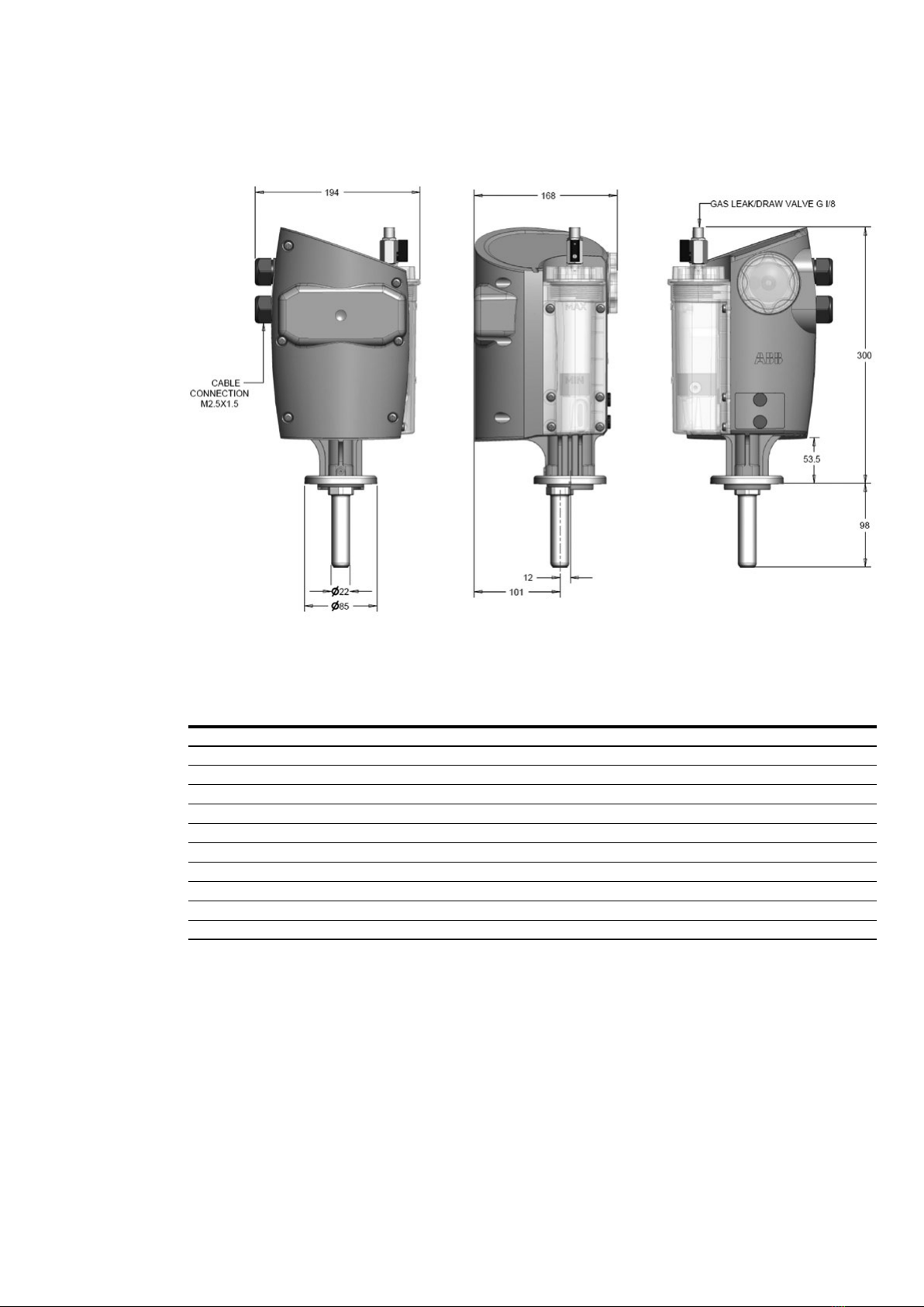
3. Installation
3.2 Installations and operating
instructions
• Before installing the device remove the protective
cap from the oil down flow hole.
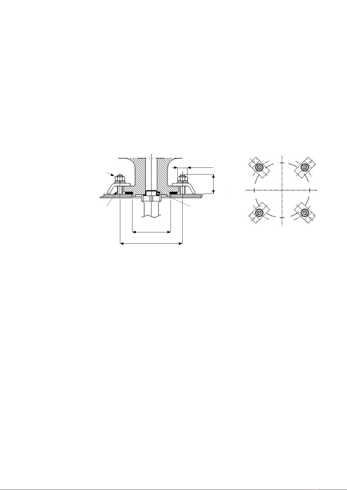
• Ensure the bearing surface is smooth and flat.
• A four stud fixing is recommended.
• Protect Comem RIS2 device from any subsequent
paint operation.
• Only install Comem RIS2 after the transformer
drying operation.
• Switch off the supply voltage prior to working on
Comem RIS2
• Operation and maintenance of Comem RIS2 should
only be carried out by skilled personnel.
• ABB disclaim all responsibility for incorrect
installation or improper use.
• On receipt of the goods please check the attached
test certificate.
• The Comem RIS2 is guaranteed against defective
parts for 12 months.
• Do not use powerful solvents or benzene's for
cleaning. A damp cloth should.
• Do not remove float from inside Comem RIS2
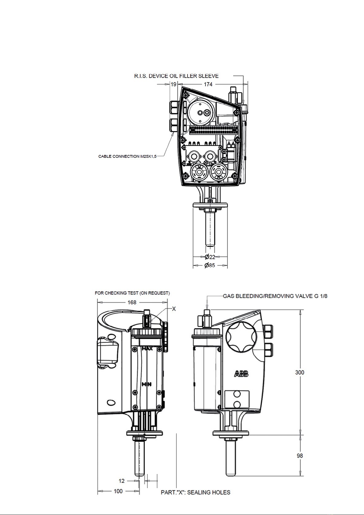
3.3 Instructions for topping up
the level on Comem RIS2
Foreword
The device is filled with oil exclusively by the
transformer manufacturer at environment
temperature. At the time of putting into service,
ensure what Comem RIS2 device is completely filled
with oil. For various reasons, the oil may be below
the set level. If the transformer is warm, due to high
environment temperature or to its own operation,
the internal pressure may increase, causing a visible
drop in the oil level in the chamber of the device.
• To solve this problem it is sufficient to remove the
lead seal on the lever of the tap 1 (see diagram),
partly unscrew cap 2, slightly turn the lever of tap
1, thus releasing pressure and causing the oil level
to rise until the device is completely full. After
operation, ensure that cap 2 is closed and clean off
any oil I that may have leaked out of the device.
• When the transformer is cold, due to a long period
of inactivity, and/or an outdoor temperature
below that of the environment, a vacuum may
form inside the transformer, with consequent fall
of the oil level visible on the external chamber of
the device. This problem may be solved by
removing the lead seal on the cap 2, unscrewing
the cap 6 and topping up the oil level slowly with
the aid of a funnel until the device is completely
full, taking care not to let it overflow. Close the
device with the cap 6.
• DO NOT USE THE OIL FILTER ON THE COMEM
RIS2 FOR GENERAL FILLING OF THE
TRANSFORMER, ONLY FOR TOPPING UP THE
DEVICE
• WHEN FILLING THE COMEM RIS2. WITH OIL
MAKE SURE THE BLEED COCK IS OPEN AND
FILL UNTIL FLOAT REACHES THE “MAX”
POSITION.
• AFTER FILLING ENSURE THE BLEED COCK AND
FILLER CAP ARE FULLY CLOSED. HAND
TIGHTEN ONLY, NO TOOLS REQUIRED.
• AFTER SETTING THE THERMOMETER POINTER
ENSURE THE PROTECTIVE WINDOW IS
SECURED, HAND TIGHTEN ONLY.
• CHECK THE CABLE GLAND M25X1,5 IS
SECURELY FITTED.
• THE EVENT OF A MAJOR OIL LEVEL VARIATION
OR HIGH GAS EVOLVEMENT THE FLOAT WILL
REACH “MIN” POSITION, TRIGGERING THE
ALARM SWITCH, IT WILL THEN BE NECESSARY
TO BLEED OFF GAS OR ADD OIL.
WARNING