SolidRF A7V-SR65703001 User manual
Signal Booster
Model: A7V-
SR65703001
Manual
If you have any questions or concerns when
installing or operating your cell phone booster,
please email us:
Support@SolidRF.ca
Please provide the invoice of your product in
your email. Or visit www.SolidRF.ca for more
information.
Systems tested and certified against FCC
standard, Equipment Class: Part 20 Wideband
Consumer Booster (CMRS)
Systems tested and certified against IC standard,
Type of Equipment: Amplifier, RSS-131
Manufactured and Warranted by
SolidRF Technology Inc. Canada
www.SolidRF.ca
Product Diagram
Package Contents
Features
Test Installation
Installation –Step By Step
Technical Specification
Quick Troubleshooting
Find Strongest Signal
Self Oscillation
Package Contents
•Main Unit
•Remote Unit
Features
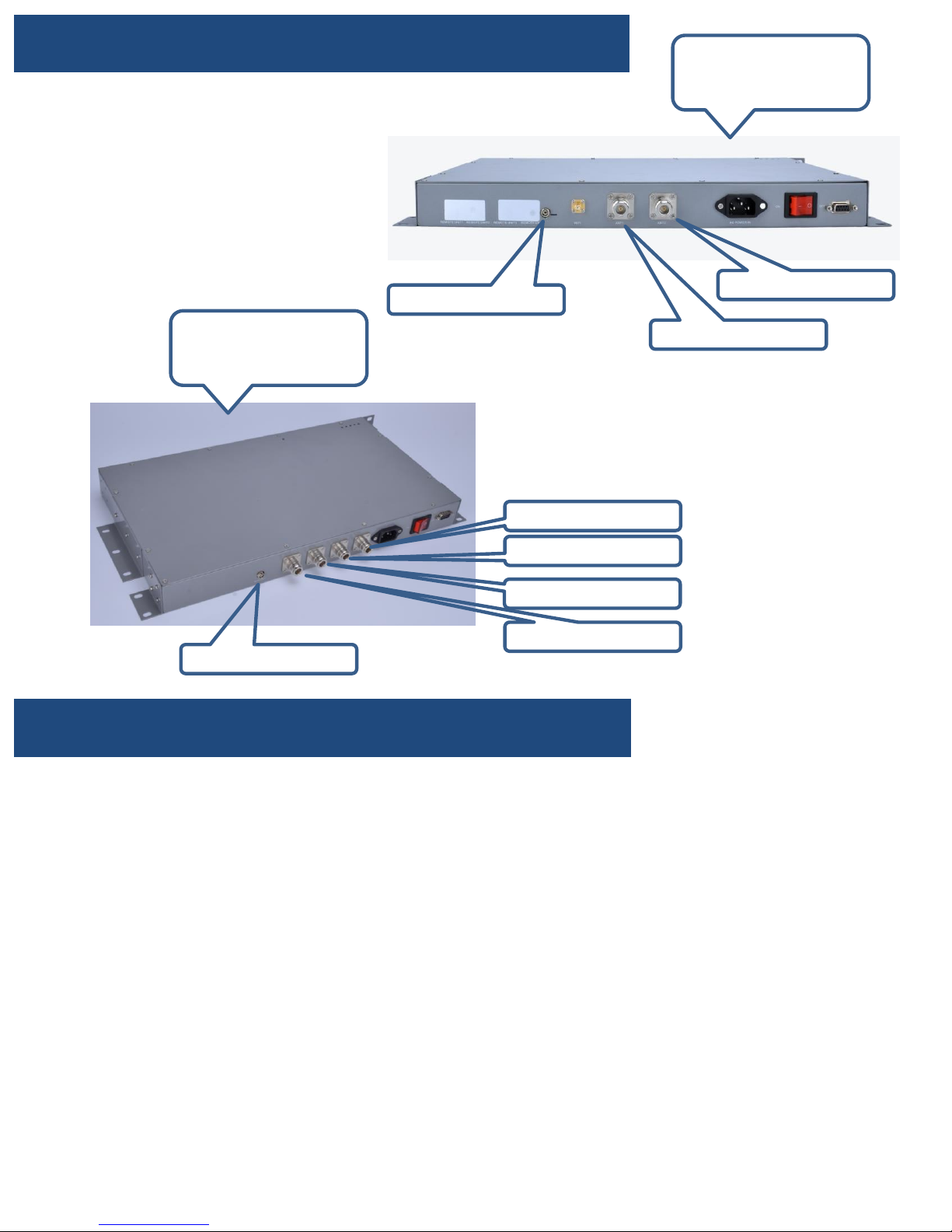
MAIN UNIT
RF Output4
•Greatly reduces dropped calls, extends signal range, and increases data rates
•Allows multiple mobile devices to be used simultaneously
•Oscillation (or interference) detection and automatic shutdown
•Overload protection circuit –protects cell towers from being overloaded
•Amplifies signal both to and from the cell tower
•Maximum 1 watts(EIRP) output power
•Works on all generations of 2G,3G and 4G
•Power control logic ensures maximum gain is within cellular standards
•Reduces radiation and extends battery life –up to 2 hours additional talk time in weak signal areas.
Supported Carriers
•AT&T 2G/3G (HSPA+)/4G LTE
•Verizon 3G/4G LTE
•T-Mobile 2G/3G/4G
•Sprint 3G/4G
•US Cellular 3G
•Metro PCS 3G/4G
•Major Canadian Carriers 2G/3G
•All other carriers using 700MHz(band12/13)/850MHz /1900 MHz/2100MHz
Remote UNIT
RF Output3
RF Output2
RF Output1
Fiber Connector
Fiber Connector Antenna 1
Antenna 2
Find a cell tower nearby!
There are a bunch of
resource online, here are
some third party websites
and app recommended.
SolidRF does NOT
guarantee the accuracy
or completeness on Third
Party content
For Canada
website:
www.cellmapper.net
app: TowerLocator(iPhone
or Android)
For U.S.
websites:
www.cellmapper.net
www.cellreception.com/t
owers
www.antennasearch.com
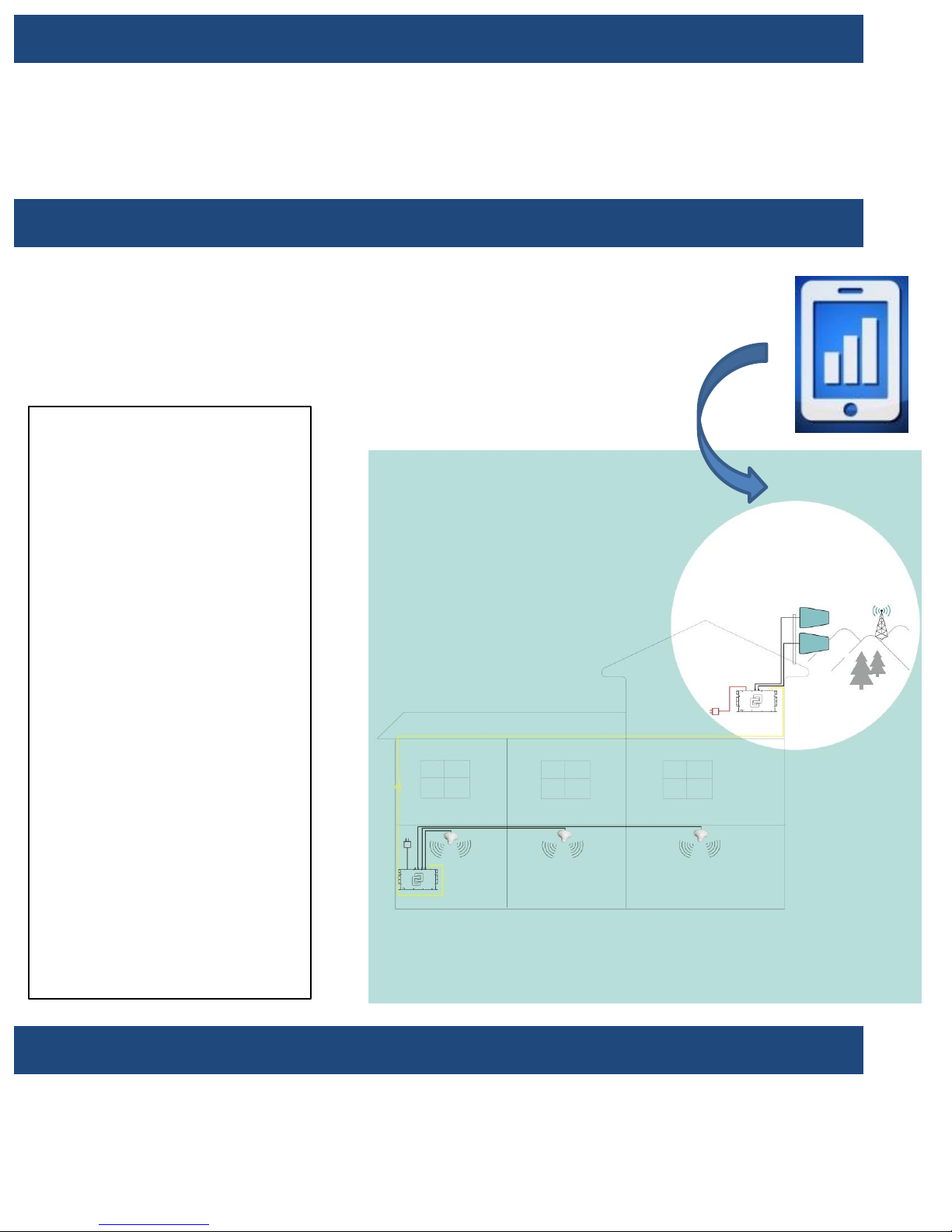
Step1: Find the strongest signal, setup outdoor antenna with cable screwed
Affected by terrain and signal propagation characteristics. More higher of
the outdoor antenna will get better signal. Find the best signal around
the house by checking the bars of the cell phone. Setup the outdoor
antenna on the top of building and connect the cable.
Step2: Find a suitable place inside home for booster nearby the power socket
Minimum Required Separation Distance Between Indoor And Outdoor Antenna:
20 meters (75 ft ) horizontal distance
4 meters (13 ft ) vertical distance(As far as possible)
Test Installation
We STRONGLY recommends doing a soft install before the formal installation.
Doing a test installation of a cell phone booster allows to get best optimal
system setup.

Step3: Introduce cables into room
Attention: Don’t excessive bending
of the cable, otherwise it will be
damaged and loss functions.
Step4: Setup Main Unit
1. Connect antenna cable to
“Antenna 1” and
“Antenna 2” connecter,
make sure pin of the
cable head smooth
import connecter’s
socket, and then screw
well till the end;
2. Connect fiber to the
“Fiber connector”;
3. Plug in power cord;
1
2 3
Step5: Setup Remote Unit
1. Connect antenna cable to
“Antenna 1” and
“Antenna 2” connecter,
make sure pin of the
cable head smooth
import connecter’s
socket, and then screw
well till the end;
2. Connect fiber to the
“Fiber connector”;
3. Plug in power cord; 12 3

The Formal Installation
OUTDOOR Unit INSTALLATION
a. Choose right position: 30 cm away from any other metallic objects, and 100 cm
away from any windows
b. Mount the antenna as the picture shows
c. Connect the cable to the outdoor antenna
•Make sure connectors are well screwed in
•Seal the connectors with glued tape
Step5: Power on and evaluate effects
1. Power on booster;
2. Observe the flashing status of “ALARM” lights;
3. If the lights lit 1 second and then goes out, that means all the test
installation is correct;
4. Now check your cell phone to see how about the signal strength
improved;
5. If light is blinking, please read the trouble shooting part of this manual;
d. The antenna must be installed at a height of not more than 10
metres above the ground.

Note1: Don’t cover the booster body with
anything, in case the power dissipation make the
booster too high temperature. Booster will shut
down when the temperature is too high itself.
Technical specification
www.SolidRFCanada.com 6
Note2: Use only the power supply provided by
SolidRF, any other products non-approved by
SolidRF or self-made power cable may damage the
booster.
Note3: Troubleshooting
•Properly: The lights on the front panel indicate
the condition of the booster. Every time the
booster is powered on, all of the lights will be
light on in green color for around 2 seconds and
then lights off, this means the booster pass the
self check and in good condition;
•Wrong condition: If any of the lights flashing in
green light, than means the isolation between
the outside antenna and inside antenna is lower
than it should be, and self oscillate occurred.
You must switch off the booster and check the
outside antenna and inside antenna immediately.
Make sure you have followed this installation
recommended, and check every thing carefully.
If you can’t fix the problem please contact the
technician or our distributor.
Outside antenna 1 Outside antenna 2
Frequency
(MHz)
LTE
(band 12)
PCS
(band 2)
Cellular
( band5)
AWS
(band 4)
LTE
(band 13)
Uplink 698-716 1850-1915 824-849 1710-1755 776-787
Downlink 728-746 1930-1995 869-894 2110-2155 746-757
Gain Uplink 55±355±355±353±355±3
Downlink 55±360±360±355±360±3
Output power 20±3dBm(Uplink)/0±3dBm(Downlink)
Noise figure <5dB
In-band Flatness <8dB
Weight 3.5Kg
EIRP 3W
Gain adjustment 30dB
Impedance 50 ohm
Operating temperature -5°~60°
Current ≦2.5A(6V DC)
Dimension(mm) 338*230*35

ATTENTION: Self Oscillation
We strongly recommend it must achieve the Minimum Required Separation Distance for the
installation. The improper installation could result in possible Self Oscillation.
Minimum Required Separation Distance (MRSD):6 meters (20 ft ) distance and 4 meters ( 13 ft )
vertical height distance.
When the antennas are too close, they
could pick up each others signals,
creating a feedback loop condition,
which is called Self Oscillation.
By FCC regulations, the cell phone
booster would automatically detect this
condition and immediately shut down to
prevent Self Oscillation from damaging
the cellular network.
(see TroubleShooting Booklet)
What is Self Oscillation:
If the booster detects Self Oscillation, it
will not operate until the condition is
corrected. One way to correct Self
Oscillation is to increase separation
distance between the antennas until the
sufficient separation distance is
achieved. Also the antennas can NOT
directly face each other.
How to correct Self Oscillation:
The Self Oscillation could cause interference to the cellular network, The FCC regulations
extremely prohibit cell phone booster users from causing interference to the cellular networks. If
you were contacted by the FCC or any wireless provider –yours or any other –and told your cell
phone booster is causing interference, you must shut it down until you can fix the interference
problem. Under most situation, it is Self Oscillation problem.
Please refer to:
https://www.fcc.gov/wireless-telecommunications/signal-boosters/faq/signal-boosters-faq.
Why is it so important to prevent Self Oscillation:
Antennas Installation Recommended
Antennas Installation Prohibited
Or
Or
≤ 90°

Quick Troubleshooting
Correct functioning:
•Power Light should be solid green
•Every time the booster is powered on, the Status Light will be lit in red for several times. It will
turn off eventually.
•Status Light is off (no mobile devices are in use) or flashing (one or more mobile devices are in
use).
Incorrect functioning: (Please see The Troubleshooting booklet for the details)
•Flashing Power Light: please contact the technical support
•Status Light: indicate the booster condition
SOLID RED –self oscillation is occurring. You must switch off the booster and check the
booster system is properly installed by re-checking each step in this manual.
SOLID GREEN –the cable from the inside unit to the outside unit is not correctly connected.
LIGHT IS OFF WITHOUT SIGNAL IMPROVEMENT - (Please see The Troubleshooting booklet
for the details)
Weather condition:
The booster outside unit, include the amplifier and the outside antenna have an integrated design.
Each are waterproof and no matter rain, snow or fog, they will work properly. However extreme
hot or cold temperatures may cause problems to the booster. Optimal functioning will occur from -
20 ℃to +50 ℃. Too high or low temperatures beyond this range will cause the booster to lower
output power to avoid damage.
If you can not fix the problem, please contact the technical support or the reseller.
SolidRF Technical Support: Support@SolidRF.ca
Find Strongest Signal
Use Cell Phone Only:
•Check the signal indicator on the cell phone display, it takes up to 30 seconds to reset a new
reading. Or place calls from several locations outside the building.
•Read signal strength with numerical value (Smart Phone Only):
iPhone: Dial *3001#12345#* then tap the CALL button, a negative number in the upper left
corner.
Android Phone: Go to Setting –About Phone –Status (SIM Status) –Signal Strength
It would a negative number instead of the five dots, the range is from -120 (weak) to -65 (strong)
Use Cell Phone During Test Installation:
•One person adjusts the outside directional antenna small angle at a time. Allow 30 seconds for
the phone to react with each turn.
•Second person read the signal strength on the cell phone inside the building.
See Test Installation Section for Find A Cell Tower Nearby
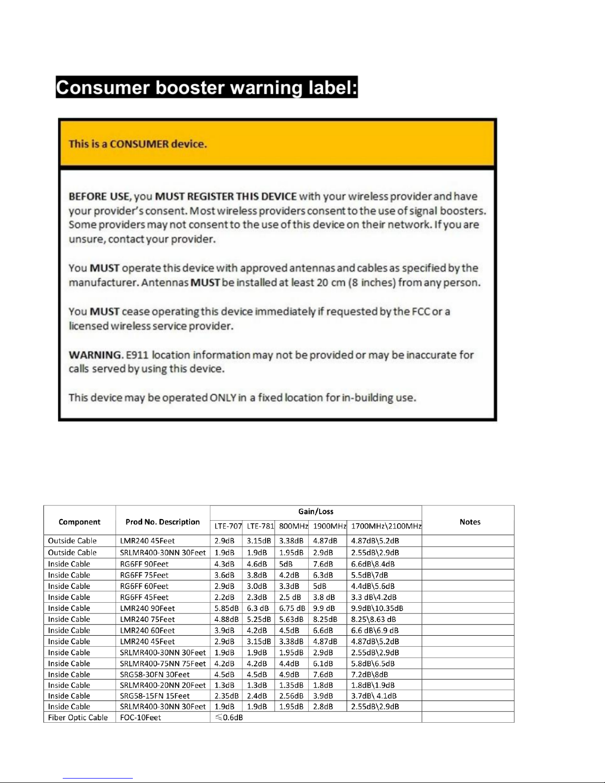
(1) Usage of unauthorized antennas, cables, and/or coupling devices may result in poor effect and, in severe cases,
equipment damage.
(2) a complete list of authorized antennas, cables, and/or coupling devices:
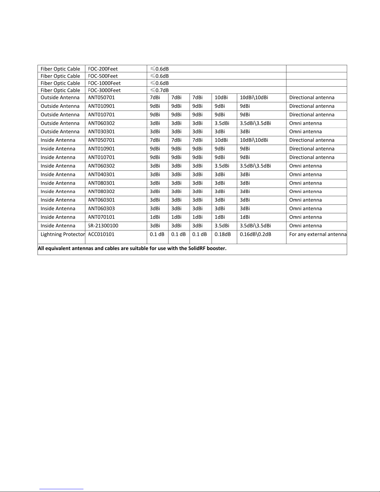
(3)the default antenna, cable, and/or coupling device that are shipped with the booster Log-periodic Antenna
Panel Antenna and CoaxialCable.
(4) The log-periodic antenna should be installed in a
be installed indoors and near the main device. If the
is completed, the direction of the log-periodic antenna can be gradually adjusted to achieve better effect.
(5) Contact information for providers:
Add:
Phone:
(6) The device has automatic sleep function, strong anti-interference ability, over-power protection function, good
heat dissipation design, and no radiation. The working noise is as low as 6DB.
Shen hen SolidRF Communications Co., Ltd
No. 8, Shop D, Block C, Shan Shui u, Long Wei Rd, Shenzhen, 518049 China
0755-83142660 Fax: 0755-86107352
ZJ
place with good outdoor signal. The panel antenna should
amplification effect is not good after the installation
Table of contents
Other SolidRF Extender manuals

SolidRF
SolidRF SOHO Dual Bands User manual

SolidRF
SolidRF Signal Plus User manual

SolidRF
SolidRF TRUE5-A User manual

SolidRF
SolidRF BP5 User manual

SolidRF
SolidRF MobileForce User manual

SolidRF
SolidRF SOHO User manual

SolidRF
SolidRF Signal Plus User manual

SolidRF
SolidRF M5U01 User manual

SolidRF
SolidRF BuildingForce 4G-X User manual

SolidRF
SolidRF Building Force Pro5 MANT User manual


