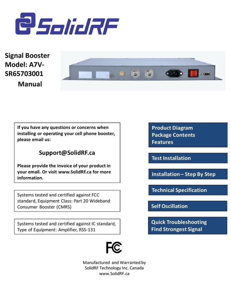
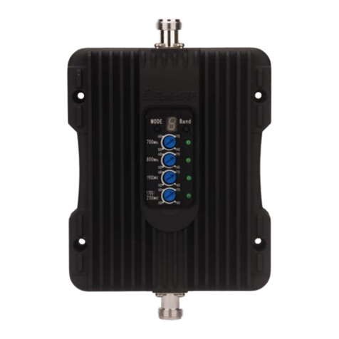
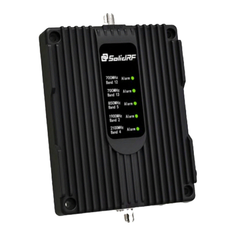
SolidRF TRUE5-A User manual

SolidRF TRUE5‐Afor
2G/3G/4Gand4GLTE
Manual
Manual
If
y
ouhavean
y
q
uestionsorconcernswhen
Product Diagram
y y q
installingoroperatingyourcellphonebooster,
pleaseemailus:
Support@SolidRF.ca
Pleaseprovidetheinvoiceofyourproductin
your email Or visit www SolidRF ca for more
Product
Diagram
PackageContents
Features
TestInstallation
Illi
S B S
your
email
.
Or
visit
www
.
SolidRF
.
ca
for
more
information.
SystemstestedandcertifiedagainstFCC
standard,EquipmentClass:Part20Wideband
ConsumerBooster(CMRS)
I
nsta
ll
at
i
on–
S
tep
B
y
S
tep
TechnicalSpecification
SelfOscillation
SystemstestedandcertifiedagainstICstandard,
TypeofEquipment:Amplifier,RSS‐131 IC QuickTroubleshooting
FindStrongestSignal
ManufacturedandWarrantedby
SolidRF TechnologyInc.Canada
www.SolidRF.ca

ProductDiagram
Package Contents
INDOORUNIT
CableConnector
OUTDOORUNIT
Cbl
C
Package
Contents
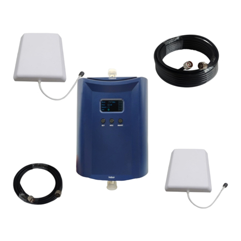
•OutdoorUnit
•IndoorUnit
•LM240Cables:1x45feet
•PowerAdapter
C
a
bl
e
C
onnector
IndoorUnit
OutdoorUnit
PowerAdapter
LM240Cable
Features
•Greatlyreducesdroppedcalls,extendssignalrange,andincreasesdatarates
•Allowsmultiplemobiledevicestobeusedsimultaneously
•Oscillation(orinterference)detectionandautomaticshutdown
•Overloadprotectioncircuit–protectscelltowersfrombeingoverloaded
•
Amplifies signal
both
to and from the cell tower
Amplifies
signal
both
to
and
from
the
cell
tower
•Maximum1watts(EIRP)outputpower
•Worksonallgenerationsof2G,3Gand4G
•Powercontrollogicensuresmaximumgainiswithincellularstandards
•Reducesradiationandextendsbatterylife–upto2hoursadditionaltalktimeinweaksignalareas.
SupportedCarriers
•AT&T2G/3G(HSPA+)/4GLTE
Vi 3G/4G LTE
•
V
er
i
zon
3G/4G
LTE
•T‐Mobile2G/3G/4G
•Sprint3G/4G
•USCellular3G
•MetroPCS3G/4G
•MajorCanadianCarriers2G/3G
•Allothercarriersusing700MHz(band12/13/17)/850MHz/1900MHz/2100MHz

TestInstallation
WeSTRONGLY recommendsdoingasoftinstallbeforetheformalinstallation.
Doingatestinstallationofacellphoneboosterallowstogetbestoptimal
systemsetup.
Step1:Findthestrongestsignal,setupoutdoorantennawithcablescrewed
Affectedbyterrainandsignalpropagationcharacteristics.Morehigherof
theoutdoorantennawillgetbettersignal.Findthebestsignalaround
thehouse bycheckingthebarsofthecellphone.Setuptheoutdoor
Findacelltowernearby!
Thereareabunchofresourceonline,hereare
somethirdpartywebsitesandapp
recommended.
antennaonthetopofbuildingandconnectthecable.
S
olidR
F
doesNOTguaranteetheaccuracyor
completenessonThirdPartycontent
ForCanada
website:www.cellmapper.net
app:TowerLocator(iPhoneorAndroid)
ForU.S.
websites:
www.cellmapper.net
www.cellreception.com/towers
www.antennasearch.com
Step2:Findasuitableplaceinsidehomeforboosternearbythepowersocket
MinimumRequiredSeparationDistance
BetweenIndoorAndOutdoorAntenna:
6meters (20
ft
)horizontal
distance
6
meters
(20
ft
)
horizontal
distance
4meters(13ft )verticaldistance(Asfaras
possible)

Step3:Introducecablesintoroom
Attention:Don’texcessivebending
ofthecable,otherwiseitwillbe
damaged and loss functions
damaged
and
loss
functions
.
Step4:Setupbooster
1. Connectcabletooutside
connecter make srepin of the
connecter
,
make
s
u
re
pin
of
the
cableheadsmoothimport
connecter’ssocket,andthen
screwwelltilltheend;
2. Pluginpowercord;
2
1
Step5:Poweronandevaluateeffects
1. Poweronbooster;
2. Observetheflashingstatusof
“ALARM”lights;
3. Ifthelightslit1secondandthen
goesout,thatmeansallthetest
installationiscorrect;
4. Nowcheckyourcellphonetosee
howaboutthesignalstrength
improved;
improved;
5. Iflightisblinking,pleasereadthe
troubleshootingpartofthis
manual;

TheFormalInstallation
OUTDOORUnitINSTALLATION
a. Chooserightposition:30cmawayfromanyothermetallicobjects,and100cm
awayfromanywindows
b
Mtth tth it h
b
.
M
oun
t
th
ean
t
ennaas
th
ep
i
c
t
ures
h
ows
c. Connectthecabletotheoutdoorantenna
•Makesureconnectorsarewellscrewedin
•Sealtheconnectorswith
g
luedta
p
e
g p

ARRANGEBOOSTER
a. Chooserightposition
RecommendedInstallationPosition
•Besuretobefarfrom
anyheatsource
•Inaventilateddry
place,temperature
rangeshouldbefrom‐
25Ԩto+50Ԩ
b
h b
b
.Mountt
h
e
b
oosteras
thepictureshows
TechnicalSpecification
Frequency
(MHz)
LTE
(band12/17)
LTE
(band13)
Cellular
(band5)
PCS
(band2/25)
AWS
(band4)
Uplink 698‐716 776‐787 824‐849 1850‐1915 1710‐1755
Downlink 728‐746 746‐757 869‐894 1930‐1995 2110‐2155
Noisefigure <5dB
In‐bandFlatness <8dB
Weight 0.7Kg
EIRP ≤1W
Operatingtemperature ‐31 Ԭ(‐35Ԩ)to122Ԭ(50Ԩ).
Current أDC5.9V/3A
Powerlevel Covera
g
eArea
CoverageArea
Note: Any cell phone booster has
attheoutdoorantennalocation
g
(sq.ft.)
Strong(5 bars onthecellphone) 10000
Medium(3~4bars onthecellphone) 3000
Weak(1~2bars onthecellphone) 800
Note:
Any
cell
phone
booster
has
alimitofamplificationpower.
Thisdependsontheoriginal
outputpoweroftheclosestcell
tower.

ATTENTION:SelfOscillation
WestronglyrecommenditmustachievetheMinimumRequiredSeparationDistanceforthe
installation The improper installation could result in possible Self Oscillation
installation
.
The
improper
installation
could
result
in
possible
Self
Oscillation
.
MinimumRequiredSeparationDistance(MRSD):6meters(20ft )distanceand4meters(13ft )
verticalheightdistance.
Whentheantennasaretooclose,they
WhatisSelfOscillation: AntennasInstallationRecommended
couldpickupeachotherssignals,
creatingafeedbackloopcondition,
whichiscalledSelfOscillation.
ByFCCregulations,thecellphone
boosterwouldautomaticallydetectthis
conditionandimmediatelyshutdownto
Or
≤90°
preventSelfOscillationfromdamaging
thecellularnetwork.
(seeTroubleShooting Booklet)
IftheboosterdetectsSelfOscillation,it
will not operate until the condition is
HowtocorrectSelfOscillation: AntennasInstallationProhibited
will
not
operate
until
the
condition
is
corrected.OnewaytocorrectSelf
Oscillationistoincreaseseparation
distancebetweentheantennasuntilthe
sufficientseparationdistanceis
achieved.AlsotheantennascanNOT
directlyfaceeachother.
Or
TheSelfOscillationcouldcauseinterferencetothecellularnetwork,TheFCCregulations
extremelyprohibitcellphoneboosterusersfromcausinginterferencetothecellularnetworks.If
youwerecontactedbytheFCCoranywirelessprovider–yoursoranyother–andtoldyourcell
p
honeboosteriscausin
g
interference
,
y
oumustshutitdownuntil
y
oucanfixtheinterference
WhyisitsoimportanttopreventSelfOscillation:
p g , y y
problem.Undermostsituation,itisSelfOscillationproblem.
Pleasereferto:
https://www.fcc.gov/wireless‐telecommunications/signal‐boosters/faq/signal‐boosters‐faq.

QuickTroubleshooting
Correctfunctioning:
•PowerLightshouldbesolidgreen
•Everytimetheboosterispoweredon,theStatusLightwillbelitinredforseveraltimes.Itwill
turnoffeventually.
•StatusLightisoff(nomobiledevicesareinuse)orflashing(oneormoremobiledevicesarein
use).
Incorrectfunctioning:(PleaseseeTheTroubleshootingbookletforthedetails)
•FlashingPowerLight:pleasecontactthetechnicalsupport
h d h b d
•StatusLig
h
t:in
d
icatet
h
e
b
oostercon
d
ition
SOLIDRED–selfoscillationisoccurring.Youmustswitchofftheboosterandcheckthe
boostersystemisproperlyinstalledbyre‐checkingeachstepinthismanual.
SOLIDGREEN–thecablefromtheinsideunittotheoutsideunitisnotcorrectlyconnected.
LIGHTISOFFWITHOUTSIGNALIMPROVEMENT‐ (PleaseseeTheTroubleshootingbooklet
forthedetails)
Wth diti
W
ea
th
ercon
diti
on:
Theboosteroutsideunit,includetheamplifierandtheoutsideantennahaveanintegrateddesign.
Eacharewaterproofandnomatterrain,snoworfog,theywillworkproperly.Howeverextreme
hotorcoldtemperaturesmaycauseproblemstothebooster.Optimalfunctioningwilloccurfrom‐
20Ԩto+50Ԩ.Toohighorlowtemperaturesbeyondthisrangewillcausetheboostertolower
outputpowertoavoiddamage.
If you can not fix the problem please contact the technical support or the reseller
If
you
can
not
fix
the
problem
,
please
contact
the
technical
support
or
the
reseller
.
SolidRF TechnicalSupport:Support@SolidRF.ca
FindStrongestSignal
UseCellPhoneOnly:
•Checkthesignalindicatoronthecellphonedisplay,ittakesupto30secondstoresetanew
reading.Orplacecallsfromseverallocationsoutsidethebuilding.
•Readsignalstrengthwithnumericalvalue(SmartPhoneOnly):
iPhone:Dial*3001#12345#*thentaptheCALLbutton,anegativenumberintheupperleft
corner.
AndroidPhone:GotoSetting– AboutPhone– Status(SIMStatus)– SignalStrength
Itwouldanegativenumberinsteadofthefivedots,therangeisfrom‐120(weak)to‐65(strong)
UCllPh Di TtItllti
U
se
C
e
ll
Ph
one
D
ur
i
ng
T
es
t
I
ns
t
a
ll
a
ti
on:
•Onepersonadjuststheoutsidedirectionalantennasmallangleatatime.Allow30secondsfor
thephonetoreactwitheachturn.
•Secondpersonreadthesignalstrengthonthecellphoneinsidethebuilding.
SeeTestInstallationSectionforFindACellTowerNearby

20

FCC Statement:

ISEDC Statement:
Toupholdnetworkprotectionstandardsandensurecompliance,allactivecellulardevicesmustmaintain
aseparationdistanceofatleastsixfeetbetweentheinsideunitantennaandoutsideunitantennaandat
leastfourfeetofseparationdistancefromtheinsideunit.Useonlythepowersupplyprovidedinthis
package.Useofanon‐SolidRF productoraccessorymayresultindamagetotheequipmentor
components of the equipment. The inside unit is designed for use in an indoor, temperature
‐
controlled
SafetyGuidelines
components
of
the
equipment.
The
inside
unit
is
designed
for
use
in
an
indoor,
temperature
controlled
environment(lessthan100degreesFahrenheit).Itisnotintendedforuseinatticsorsimilarlocations
wheretemperaturesmaybeinexcessofthatrange.
RFSafetyWarning:Anyantennausedwiththisdevicemustbelocatedatleast8inchesfromallpersons.
CPC‐2‐1‐05—ZoneEnhancers‐ Spectrummanagementandtelecommunications
http://www.ic.gc.ca/eic/site/smt‐gst.nsf/eng/sf08942.html
Mobile phone is the minimum distance to use indoor antenna
Inside server antenna types Minimum separation distances D (m)
Ceiling mounted (e.g., dome‐type) antennas 2
Wall mounted (i.e., panel or other type)
antennas
1.0 or 2*
Table top antennas 1.0
ISED

Antenna Kitting Information
Component
Typespecification
Gain/Loss
Manufacturer
LTE‐707LTE‐781 800MHz 1900MHz 1700MHz\2100MHz
id
bl
d
d
d
d
d
\
d
ibl
Outs
id
eCa
bl
eLMR24045Feet 2.9
d
B3.15
d
B3.38
d
B4.87
d
B4.87
d
B
\
5.2
d
BSu
i
rongca
bl
e
OutsideCableSRLMR400‐30NN30Feet1.9dB1.9dB1.95dB 2.9dB2.55dB\2.9dBSuirongcable
InsideCableRG6FF90Feet 4.3dB4.6dB 5dB 7.6dB 6.6dB\8.4dB Suirongcable
InsideCableRG6FF75Feet 3.6dB3.8dB 4.2dB 6.3dB 5.5dB\7dB Suirongcable
InsideCableRG6FF60Feet 2.9dB3.0dB 3.3dB 5dB 4.4dB\5.6dB Suirongcable
InsideCableRG6FF45Feet 2.2dB2.3dB 2.5 dB 3.8 dB 3.3 dB\4.2dB Suirongcable
InsideCableLMR24090Feet 5.85dB6.3 dB 6.75 dB 9.9 dB 9.9dB\10.35dB Suirongcable
InsideCableLMR24075Feet 4.88dB5.25dB 5.63dB 8.25dB 8.25\8.63 dB Suirongcable
InsideCableLMR24060Feet 3.9dB4.2dB 4.5dB 6.6dB 6.6 dB\6.9 dB Suirongcable
InsideCableLMR24045Feet 2.9dB3.15dB 3.38dB 4.87dB 4.87dB\5.2dB Suirongcable
In
si
de
Cable
SRLMR400
30
NN
30
Feet
19
dB
19
dB
195
dB
29
dB
255
dB
\
29
dB
Suirongcable
In
si
de
Cable
SRLMR400
‐
30
NN
30
Feet
1
.
9
dB
1
.
9
dB
1
.
95
dB
2
.
9
dB
2
.
55
dB
\
2
.
9
dB
Suirongcable
InsideCableSRLMR400‐75NN75Feet4.2dB4.2dB 4.4dB 6.1dB 5.8dB\6.5dB Suirongcable
InsideCableSRG58‐30FN30Feet4.5dB4.5dB 4.9dB 7.6dB 7.2dB\8dB Suirongcable
InsideCableSRLMR400‐20NN20Feet1.3dB1.3dB 1.35dB 1.8dB 1.8dB\1.9dB Suirongcable
InsideCableSRG58‐15FN15Feet2.35dB2.4dB 2.56dB 3.9dB 3.7dB\ 4.1dB Suirongcable
InsideCableSRLMR400‐30NN30Feet1.9dB1.9dB 1.95dB 2.8dB 2.55dB\2.9dB Suirongcable
OutsideAntennaANT050701
7dBi7dBi7dBi10dBi10dBi\10dBi
Shenzhen Dachi Communications
Co., Ltd.
OutsideAntennaANT0109019dBi9dBi9dBi9dBi9dBi
Shenzhen Dachi Communications
Co., Ltd.
OutsideAntennaANT0107019dBi9dBi9dBi9dBi9dBi
Shenzhen Dachi Communications
Co., Ltd.
OutsideAntennaANT0603023dBi3dBi3dBi3.5dBi3.5dBi\3.5dBi
Shenzhen Dachi Communications
Co., Ltd.
OutsideAntennaANT0303013dBi3dBi3dBi3dBi3dBi
Shenzhen Dachi Communications
Co., Ltd.
OutsideAntennaANT0603023dBi3dBi3dBi3.5dBi 3.5dBi\3.5dBi
Shenzhen Dachi Communications
Co., Ltd.
OutsideAntennaANT0303013dBi3dBi3dBi3dBi3dBi
Shenzhen Dachi Communications
Co., Ltd.
InsideAntennaANT050701 7dBi 7dBi 7dBi 10dBi 10dBi
\
10dBi
Shenzhen Dachi Communications
\
Co., Ltd.
InsideAntennaANT0109019dBi9dBi9dBi9dBi9dBi
Shenzhen Dachi Communications
Co., Ltd.
InsideAntennaANT0107019dBi9dBi9dBi9dBi9dBi
Shenzhen Dachi Communications
Co., Ltd.
InsideAntennaANT0603023dBi3dBi3dBi3.5dBi 3.5dBi\3.5dBi
Shenzhen Dachi Communications
Co., Ltd.
InsideAntennaANT0403013dBi3dBi3dBi3dBi3dBi
Shenzhen Dachi Communications
Co., Ltd.
In
side
Antenna
ANT08030
1
3
dBi
3
dBi
3
dBi
3
dBi
3
dBi
Shenzhe
n
Dach
i
Communications
In
side
Antenna
ANT08030
1
3
dBi
3
dBi
3
dBi
3
dBi
3
dBi
Shenzhe
n
Dach
i
Communications
Co., Ltd.
InsideAntennaANT0803023dBi3dBi3dBi3dBi3dBi
Shenzhen Dachi Communications
Co., Ltd.
InsideAntennaANT0603013dBi3dBi3dBi3dBi3dBi
Shenzhen Dachi Communications
Co., Ltd.
InsideAntennaANT0603033dBi3dBi3dBi3dBi3dBi
Shenzhen Dachi Communications
Co., Ltd.
InsideAntennaANT0701011dBi1dBi1dBi1dBi1dBi
Shenzhen Dachi Communications
Co., Ltd.
I
id
A
SR
21300100
3
dBi
3
dBi
3
dBi
35
dBi
35
dBi
\
35
dBi
Sh h
Dh
i
Citi
I
ns
id
e
A
ntenna
SR
‐
21300100
3
dBi
3
dBi
3
dBi
3
.
5
dBi
3
.
5
dBi
\
3
.
5
dBi
Sh
enz
h
en
D
ac
h
i
C
ommun
i
ca
ti
ons
Co., Ltd.
LightningProtectorACC010101
0.1dB0.1dB 0.1dB 0.18dB 0.16dB\0.2dB
Shenzhen Dachi Communications
Co., Ltd.
AllequivalentantennasandcablesaresuitableforusewiththeSolidRFbooster.

Table of contents
Other SolidRF Extender manuals
SolidRF
SolidRF BP5 User manual

SolidRF
SolidRF M5U01 User manual
SolidRF
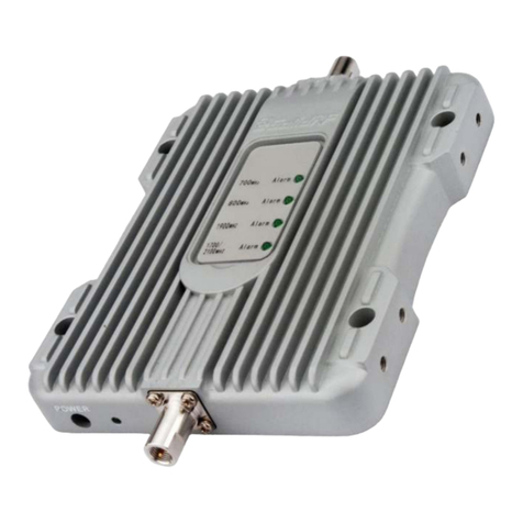
SolidRF MobileForce 4G User manual
SolidRF
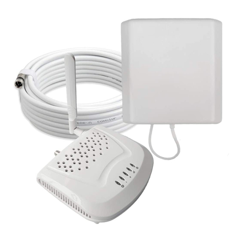
SolidRF SOHO Dual Bands User manual
SolidRF
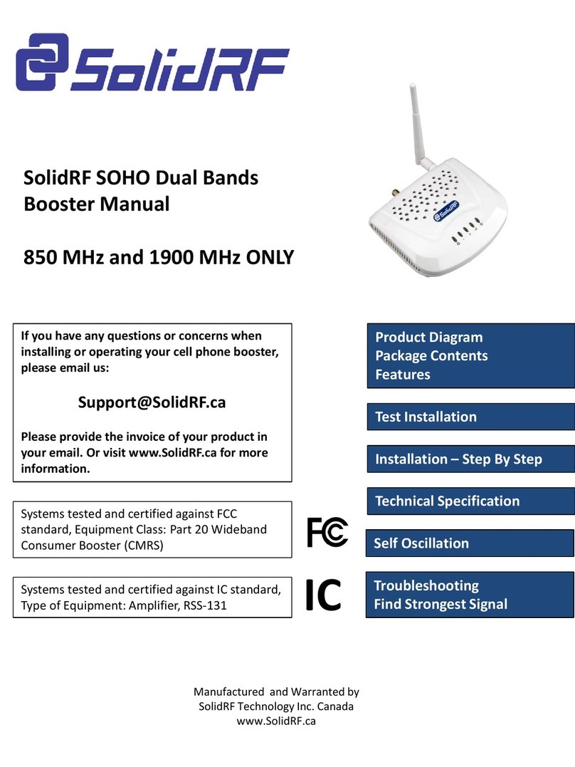
SolidRF SOHO User manual
SolidRF
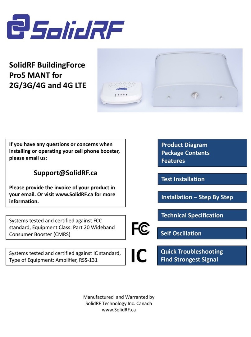
SolidRF Building Force Pro5 MANT User manual
SolidRF
SolidRF Soho Tri Bands R3U01 User manual

SolidRF
SolidRF SR14652002A User manual

SolidRF
SolidRF E2 User manual
SolidRF
SolidRF MobileForce User manual
Popular Extender manuals by other brands

Home Easy
Home Easy HE-104 user manual
Rose electronics
Rose electronics CrystalLink USB3.1 Fiber Dual Port Installation
SureCall
SureCall Fusion4Home 3.0 CA Quick install guide
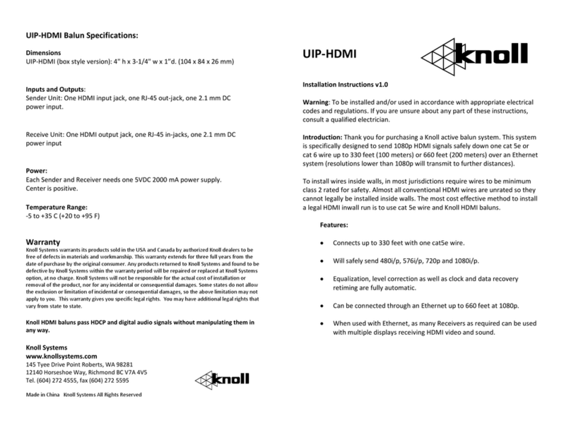
Knoll
Knoll UIP-HDMI installation instructions
Rose electronics
Rose electronics CRK-1P1V Installation and operation manual
Bennett
Bennett 901 E manual
