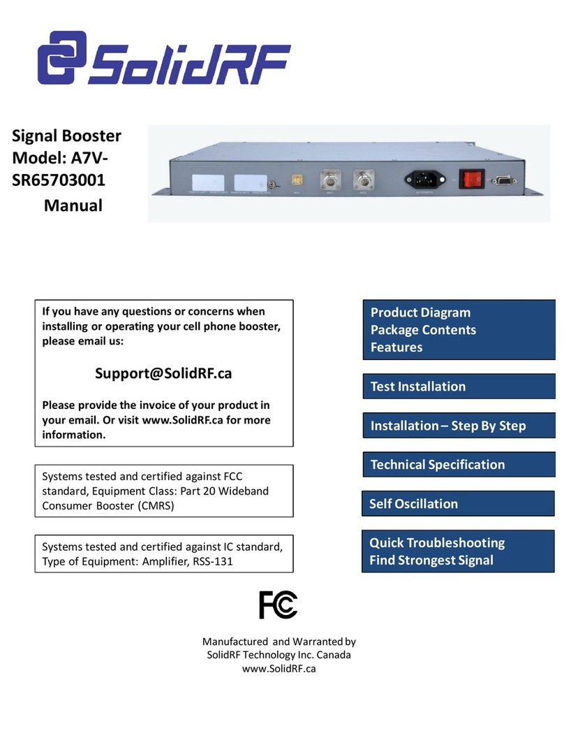
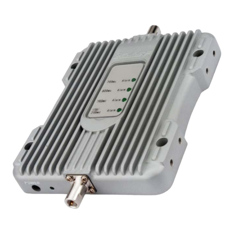
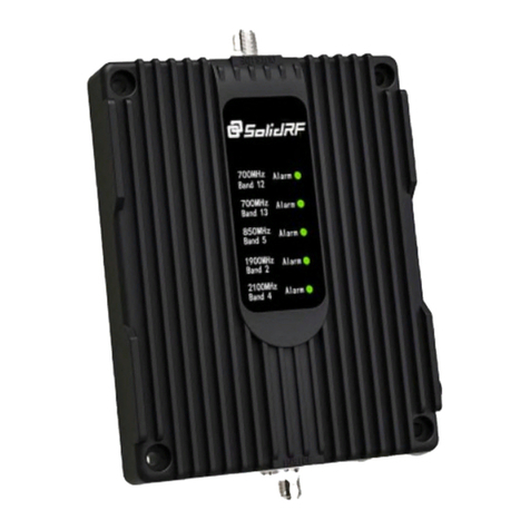
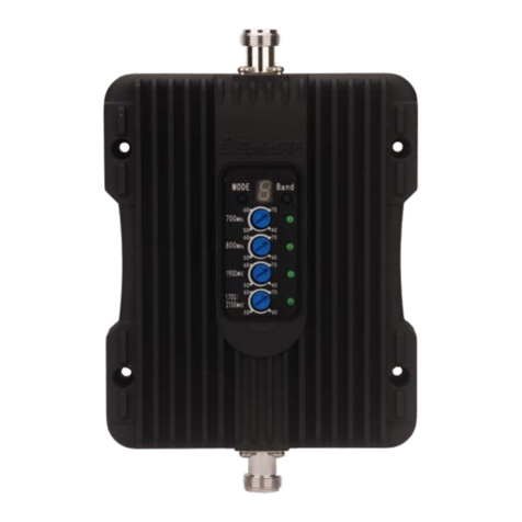
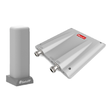
SolidRF Building Force Pro5 MANT User manual

SolidRF BuildingForce
Pro5 MANT for
2G/3G/4G and 4G LTE
If you have any questions or concerns when
installing or operating your cell phone booster,
please email us:
Support@SolidRF.ca
Please provide the invoice of your product in
your email. Or visit www.SolidRF.ca for more
information.
Systems tested and certified against FCC
standard, Equipment Class: Part 20 Wideband
Consumer Booster (CMRS)
Systems tested and certified against IC standard,
Type of Equipment: Amplifier, RSS-131
Manufactured and Warranted by
SolidRF Technology Inc. Canada
www.SolidRF.ca
IC
Product Diagram
Package Contents
Features
Test Installation
Installation –Step By Step
Technical Specification
Quick Troubleshooting
Find Strongest Signal
Self Oscillation

Product Diagram
Package Contents
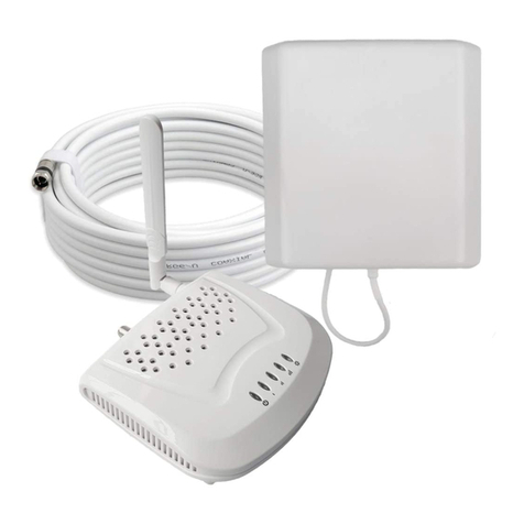
•Outdoor Unit
•Indoor Unit
•LM240 Cables: 1 x 45 feet
•Power Adapter
Features
INDOOR UNIT
Cable Connector OUTDOOR UNIT
Cable Connector
Warning Lights
Indoor Unit
Outdoor Unit
Power Adapter
LM240 Cable
•Greatly reduces dropped calls, extends signal range, and increases data rates
•Allows multiple mobile devices to be used simultaneously
•Oscillation (or interference) detection and automatic shutdown
•Overload protection circuit –protects cell towers from being overloaded
•Amplifies signal both to and from the cell tower
•Maximum 1 watts(EIRP) output power
•Works on all generations of 2G,3G and 4G
•Power control logic ensures maximum gain is within cellular standards
•Reduces radiation and extends battery life –up to 2 hours additional talk time in weak signal areas.
Supported Carriers
•AT&T 2G/3G (HSPA+)/4G LTE
•Verizon 3G/4G LTE
•T-Mobile 2G/3G/4G
•Sprint 3G/4G
•US Cellular 3G
•Metro PCS 3G/4G
•Major Canadian Carriers 2G/3G
•All other carriers using 700MHz(band12/13/17)/850MHz /1900 MHz/2100MHz

Find a cell tower nearby!
There are a bunch of resource online, here are
some third party websites and app
recommended.
SolidRF does NOT guarantee the accuracy or
completeness on Third Party content
For Canada
website: www.cellmapper.net
app: TowerLocator(iPhone or Android)
For U.S.
websites:
www.cellmapper.net
www.cellreception.com/towers
www.antennasearch.com
Step1: Find the strongest signal, setup outdoor antenna with cable screwed
Affected by terrain and signal propagation characteristics. More higher of
the outdoor antenna will get better signal. Find the best signal around
the house by checking the bars of the cell phone. Setup the outdoor
antenna on the top of building and connect the cable.
Step2: Find a suitable place inside home for booster nearby the power socket
Minimum Required Separation Distance
Between Indoor And Outdoor Antenna:
6 meters (20 ft ) horizontal distance
4 meters (13 ft ) vertical distance(As far as
possible)
Test Installation
We STRONGLY recommends doing a soft install before the formal installation.
Doing a test installation of a cell phone booster allows to get best optimal
system setup.

Step5: Power on and evaluate effects
Step3: Introduce cables into room
Attention: Don’t excessive bending
of the cable, otherwise it will be
damaged and loss functions.
Step4: Setup booster
1. Connect cable to outside
connecter, make sure pin of the
cable head smooth import
connecter’s socket, and then
screw well till the end;
2. Plug in power cord;
1. Power on booster;
2. Observe the flashing status of
“ALARM” lights;
3. If the lights lit 1 second and then
goes out, that means all the test
installation is correct;
4. Now check your cell phone to see
how about the signal strength
improved;
5. If light is blinking, please read the
trouble shooting part of this
manual;
1
2

The Formal Installation
OUTDOOR Unit INSTALLATION
a. Choose right position: 30 cm away from any other metallic objects, and 100 cm
away from any windows
b. Mount the antenna as the picture shows
c. Connect the cable to the outdoor antenna
•Make sure connectors are well screwed in
•Seal the connectors with glued tape

Technical Specification
Power level
at the outdoor antenna location Coverage Area
(sq. ft.)
Strong (5 bars on the cellphone) 10000
Medium (3~4 bars on the cellphone) 3000
Weak (1~2 bars on the cellphone) 800
Coverage Area
Note: Any cell phone booster has
a limit of amplification power.
This depends on the original
output power of the closest cell
tower.
Frequency
(MHz)
LTE
(band 12)
LTE
(band 13)
Cellular
( band5)
PCS
(band 25/2)
AWS
(band 4)
Uplink 698-716 776-787 824-849 1850-1915 1710-1755
Downlink 728-746 746-757 869-894 1930-1995 2110-2155
Gain Uplink 55±2 55±2 55±2 60±2 60±2
Downlink 60±2 60±2 60±2 65±2 65±2
Output power 26±2dBm(Uplink)/0±2dBm(Downlink)
Noise figure <5dB
In-band Flatness <8dB
Weight 0.7Kg
EIRP 1W
Operating temperature -5°~60°
Current ≦1.5A(6V DC)
Dimension(mm) 155*125*25
ARRANGE BOOSTER
a. Choose right position
•Be sure to be far from
any heat source
•In a ventilated dry
place, temperature
range should be from -
25 ℃to +50 ℃
b. Mount the booster as
the picture shows
Recommended Installation Position

ATTENTION: Self Oscillation
We strongly recommend it must achieve the Minimum Required Separation Distance for the
installation. The improper installation could result in possible Self Oscillation.
Minimum Required Separation Distance (MRSD):6 meters (20 ft ) distance and 4 meters ( 13 ft )
vertical height distance.
When the antennas are too close, they
could pick up each others signals,
creating a feedback loop condition,
which is called Self Oscillation.
By FCC regulations, the cell phone
booster would automatically detect this
condition and immediately shut down to
prevent Self Oscillation from damaging
the cellular network.
(see TroubleShooting Booklet)
What is Self Oscillation:
If the booster detects Self Oscillation, it
will not operate until the condition is
corrected. One way to correct Self
Oscillation is to increase separation
distance between the antennas until the
sufficient separation distance is
achieved. Also the antennas can NOT
directly face each other.
How to correct Self Oscillation:
The Self Oscillation could cause interference to the cellular network, The FCC regulations
extremely prohibit cell phone booster users from causing interference to the cellular networks. If
you were contacted by the FCC or any wireless provider –yours or any other –and told your cell
phone booster is causing interference, you must shut it down until you can fix the interference
problem. Under most situation, it is Self Oscillation problem.
Please refer to:
https://www.fcc.gov/wireless-telecommunications/signal-boosters/faq/signal-boosters-faq.
Why is it so important to prevent Self Oscillation:
Antennas Installation Recommended
Antennas Installation Prohibited
Or
Or
≤ 90°

Quick Troubleshooting
Correct functioning:
•Power Light should be solid green
•Every time the booster is powered on, the Status Light will be lit in red for several times. It will
turn off eventually.
•Status Light is off (no mobile devices are in use) or flashing (one or more mobile devices are in
use).
Incorrect functioning: (Please see The Troubleshooting booklet for the details)
•Flashing Power Light: please contact the technical support
•Status Light: indicate the booster condition
SOLID RED –self oscillation is occurring. You must switch off the booster and check the
booster system is properly installed by re-checking each step in this manual.
SOLID GREEN –the cable from the inside unit to the outside unit is not correctly connected.
LIGHT IS OFF WITHOUT SIGNAL IMPROVEMENT - (Please see The Troubleshooting booklet
for the details)
Weather condition:
The booster outside unit, include the amplifier and the outside antenna have an integrated design.
Each are waterproof and no matter rain, snow or fog, they will work properly. However extreme
hot or cold temperatures may cause problems to the booster. Optimal functioning will occur from -
20 ℃to +50 ℃. Too high or low temperatures beyond this range will cause the booster to lower
output power to avoid damage.
If you can not fix the problem, please contact the technical support or the reseller.
SolidRF Technical Support: Support@SolidRF.ca
Find Strongest Signal
Use Cell Phone Only:
•Check the signal indicator on the cell phone display, it takes up to 30 seconds to reset a new
reading. Or place calls from several locations outside the building.
•Read signal strength with numerical value (Smart Phone Only):
iPhone: Dial *3001#12345#* then tap the CALL button, a negative number in the upper left
corner.
Android Phone: Go to Setting –About Phone –Status (SIM Status) –Signal Strength
It would a negative number instead of the five dots, the range is from -120 (weak) to -65 (strong)
Use Cell Phone During Test Installation:
•One person adjusts the outside directional antenna small angle at a time. Allow 30 seconds for
the phone to react with each turn.
•Second person read the signal strength on the cell phone inside the building.
See Test Installation Section for Find A Cell Tower Nearby

www.SolidRFCanada.com 9
Warnings and Recommendations
Warning: This consumer booster is for Consumer use only.
Warning: Unauthorized antennas, cables, and/or coupling devices are prohibited by FCC regulations. Please
contact FCC for details: 1-888-CALL-FCC.
Warning: Outside antenna orientation must be back side of inside antenna is to prevent the indoor antenna
receiving the signal emitted by outside antenna. Otherwise it will cause self-oscillation of booster.
Warning: RF safety, any antenna used with this device must be located at 20 cm (8 inches) away from
persons or by bystanders.
Warning: It will damage the mobile device and the booster if connect them with a cable directly.
Warning: Use the power supply provided by SolidRF only. Other power supplies may cause damage of the
booster.
Warning: Antenna installation is restricted to 10 meters or less height above ground, even if the antenna is
installed inside when used with a mobile device that operates in the 1710-1755 MHz band. Violation of this
requirement may subject the owner of the booster to potential FCC enforcement actions.
Warning: Never point the front of a directional antenna toward the inside antenna. Verify that both the
outside antenna and the inside antenna are connected to the booster before powering up the booster.
(EN) RF Exposure: The manufacturer’s rated output power of this equipment is for single carrier
operation. For situations when multiple carrier signals are present, the rating would have to be reduced
by 3.5 dB, especially where the output is re-radiated and can cause interference to adjacent band users.
This power reduction is to be by means of input power or gain reduction and not by an attenuating at
the output of the device.
(FR) Exposition RF: La puissance de sortie nominale du fabricant de cet équipement est pour le
fonctionnement d'une seule porteuse. Pour les situations où plusieurs signaux de porteuse sont
présents, la note devrait être réduite de 3,5 dB, en particulier lorsque le signal de sortie est rayonné et
peut causer des interférences aux utilisateurs de bande adjacents. Cette réduction de puissance doit se
faire au moyen d'une puissance d'entrée ou d'une réduction de gain et non pas par un atténuateur à la
sortie du dispositif.
(EN) This device complies with Industry Canada license-exempt RSS standard(s). Operation is subject to
the following two conditions: (1) this device may not cause interference, and (2) this device must accept
any interference, including interference that may cause undesired operation of the device.
(FR) Le présent appareil est conforme aux CNR d'Industrie Canada applicables aux appareils radio
exempts de licence. L'exploitation est autorisée aux deux conditions suivantes : (1) l'appareil ne doit pas
produire de brouillage, et (2) l'utilisateur de l'appareil doit accepter tout brouillage radioélectrique subi,
même si le brouillage est susceptible d'en compromettre le fonctionnement.
(EN) This system has been evaluated for RF Exposure per RSS-102 and is in compliance with the limits
specified by Health Canada Safety Code 6. The system must be installed at a minimum separation
distance from the antenna to a general bystander of 8 inches (20 cm) to maintain compliance with the
General Population limits.
(FR) L’exposition aux radiofréquences de ce système a été évaluée selon la norme RSS-102 et est jugée
conforme aux limites établies par le Code de sécurité 6 de Santé Canada. Le système doit être installé à
une distance minimale de 8 pouces (21 cm) séparant l’antenne d’une personne présente en conformité
avec les limites permises d’exposition du grand public.

www.SolidRFCanada.com 10
This device complies with Part 15 of FCC Rules. Operation is subject to the following two conditions: (1) this device
may not cause harmful interference, and (2) this device must accept any interference received, including interference
that may cause undesired operation.
This equipment has been tested and found to comply with the limits for a Class B digital device, pursuant to Part 15 of
the FCC Rules. These limits are designed to provide reasonable protection against harmful interference in a residential
installation. This equipment generates and can radiate radio frequency energy and, if not installed and used in
accordance with the instructions, may cause harmful interference to radio communications. However, there is no
guarantee that interference will not occur in a particular installation. If this equipment does cause harmful interference
to radio or television reception, which can be determined by turning the equipment off and on, the user is encouraged
to try to correct the interference by one or more of the following measures:
-- Reorient or relocate the receiving antenna.
-- Increase the separation between the equipment and receiver.
-- Connect the equipment into an outlet on a circuit different from that to which the receiver is connected.
-- Consult the dealer or an experienced radio/TV technician for help
Contact information for providers
A subscriber must have the consent of a wireless provider to operate a consumer signal booster. Please register your
booster with your wireless service provider, refer to contact information for providers:
Sprint:
signalbooster@sprint.com
T-Mobile:
www.T-Mobile.com/BoosterRegistration
https://support.t-mobile.com/docs/DOC-9827
Verizon:
http://www.verizonwireless.com/wcms/consumer/register-signal-booster.html
AT&T:
https://securec45.securewebsession.com/attsignalbooster.com/
U.S. Cellular:
http://www.uscellular.com/uscellular/support/fcc-booster-registration.jsp
Metro PCS
https://www.metropcs.com/support/signal-booster
This is a CONSUMER device
BEFURE USE ,you MUST REGISTER THIS DEVICE with your wireless provider and have your
provider’s consent .Most wireless provider consent to the use of signal boosters .Some
provider may not consent to the use of this device on their network .If you are unsure,
contact your provider.
You MUST operate this device with approved antenna and cables as specified by the
manufacturer .Antennas MUST be installed at least 20cm (8inches) from any person.
You MUST cease operating this device immediately if requested by the FCC or a licensed
wireless service provider.
WARNING.E911 location information may not be provided or may be inaccurate for calls
served by using this device.
This device may be operated ONLY in a fixed location for in-building use.
Description of network protection features:
This booster including safeguards to protect the cellular network from interference. Each Signal Booster is individually tested
and factory set to ensure FCC compliance.
1. The Signal Booster cannot be adjusted without factory reprogramming or disabling the hardware.
2. The Signal Booster will amplify, but ONLY incoming and outgoing signals in order to increase coverage of authorized
frequency bands.
3. If the Signal Booster is not in use for five minutes, it will reduce gain until a signal is detected.
4. If a detected signal is too high in a frequency band, or if the Signal Booster detects an oscillation, the Signal Booster will
automatically turn the power off on that band.
5. For a detected oscillation the Signal Booster will automatically resume normal operation after a minimum of 1 minute.
After 5 times consecutive such automatic restarts, if the detected oscillation still remains, any problematic bands are
permanently shut off until the Signal Booster has been manually restarted by reconnecting power supply to the Signal
Booster.
6. Noise power, gain, and linearity are maintained by the Signal Booster’s microprocessor.
Table of contents
Other SolidRF Extender manuals

SolidRF
SolidRF MobileForce 4G User manual

SolidRF
SolidRF Signal Plus User manual

SolidRF
SolidRF E2 User manual

SolidRF
SolidRF Signal Plus User manual

SolidRF
SolidRF SR14652002A User manual

SolidRF
SolidRF TRUE5-A User manual

SolidRF
SolidRF M5U01 User manual

SolidRF
SolidRF MobileForce User manual

SolidRF
SolidRF Soho Tri Bands R3U01 User manual

SolidRF
SolidRF BP5 User manual