Solidscape 3Z Series User manual

I
3z series
User Manual
Part Number 840180 Rev F
August 2013

II
Trademarks
Solidscape®, 3Z™PRO, 3Z™STUDIO, 3Z™MAX , 3Z™Touch, 3Z™Remote, 3Z™Print, 3Z™Works,
3Z™Analyzer, 3Z™Organizer, 3Z™Base, 3Z™Model, 3Z™Support are either trademarks or
registered trademarks of Solidscape®, Inc.
is a registered trademark of Solidscape®, Inc.
BIOACT®is a registered trademark of Petroferm, Inc.
Windows®is a registered trademark of Microsoft Corporation in the United States and/or other
Countries.
All other brand and product names appearing in this manual are trademarks or registered
trademarks of their respective holders.

IV
Class A Digital Device
This equipment has been tested and found to comply with the limits for a class A digital device,
pursuant to Part 15 of the FCC Rules. These limits are designed to provide reasonable
protection against harmful interference when the equipment is operated in a commercial
environment. This equipment generates, uses, and can radiate radio frequency energy and, if
not installed and used in accordance with the instruction manual, may cause harmful
interference to radio communications. Operation of this equipment in a residential area is likely
to cause harmful interference in which case the user will be required to correct the interference
at their own expense.
This Class A digital apparatus meets all requirements of the Canadian Interference-causing
Equipment Regulations.
Cet appareil numérique de la classe A respecte toutes les exigences du Règlement sur le
matériel brouilleur du Canada.

V
Limited Warranty Statement
3Z Series
Solidscape, Inc. warrants this 3Z Series System to be in good working order for a period of one
year from the date of installation and registration. Should this Product exhibit any manufacturing
defects during the warranty period, Solidscape or its authorized agent will, at its option, replace,
repair or provide replacement parts for this Product at no additional charge except as set forth
below. Replacement parts and / or Product will be furnished on an exchange basis. All replaced
parts and Product become the property of Solidscape. The use of any parts or materials other
than those provided by Solidscape void this warranty. This limited warranty does not include
service to repair damage to the Product resulting from; accident, disaster, misuse, abuse, or
modification to the Product or installation by a person not authorized by Solidscape. This limited
warranty is activated only upon registering the Product with the manufacturer. Failure to register
this Product immediately upon installation will prevent activation of the warranty. This limited
warranty is transferable under the conditions of the Solidscape Warranty transfer policy.
Limited warranty service may be obtained by delivering the Product to an authorized Solidscape
warranty center. A dated proof of purchase from Solidscape or an authorized Solidscape dealer
must accompany the claim. The customer will ship the replacement parts and / or Product in the
original container or an equivalent. The customer is responsible for all shipping and insurance
charges. Failure to properly package, ship or insure the replacement parts and / or Product will
result in the customer assuming full responsibility for all damage or loss incurred in transit.
THE FOREGOING WARRANTY IS EXCLUSIVE AND IN LIEU OF ALL OTHER WARRANTIES,
WHETHER WRITTEN, ORAL OR IMPLIED INCLUDING ANY WARRANTY OF
MERCHANTABILITY OR FITNESS FOR PARTICULAR PURPOSE. SOLIDSCAPE SHALL
NOT BE RESPONSIBLE FOR INCIDENTAL OR CONSEQUENTIAL DAMAGES ARISING
FROM OUR PRODUCTS NOT BEING AS WARRANTED AND THE REMEDIES SHALL BE
LIMITED TO THOSE SET ABOVE.
IF THIS PRODUCT EXHIBITS MANUFACTURING DEFECTS DURING THE WARRANTY
PERIOD AS DESCRIBED ABOVE, YOUR SOLE REMEDY SHALL BE REPAIR OR
REPLACEMENT AS PROVIDED ABOVE. IN NO EVENT WILL SOLIDSCAPE BE LIABLE TO
YOU FOR ANY DAMAGES, INCLUDING ANY LOST PROFITS, LOST SAVINGS, OR OTHER
INCIDENTAL OR CONSEQUENTIAL DAMAGES ARISING FROM THE USE OR INABILITY TO
USE SUCH PRODUCT. THE REMEDY DESCRIBED ABOVE REMAINS THE SOLE REMEDY
EVEN IF SOLIDSCAPE OR AN AUTHORIZED DEALER HAS BEEN ADVISED OF THE
POSSIBILITY OF SUCH DAMAGES, OR FOR ANY CLAIM BY ANOTHER PARTY.

VI

Table of Contents VII
Table of Contents
3ZTMSERIES ................................................................................................................................ III
LIMITED WARRANTY STATEMENT...........................................................................................V
3Z SERIES....................................................................................................................................V
TABLE OF CONTENTS .............................................................................................................VII
LIST OF FIGURES ......................................................................................................................IX
CAUTIONS ..................................................................................................................................XI
CHAPTER 1 - SYSTEM OVERVIEW ........................................................................................... 1
1.1 LED STATUS INDICATORS ................................................................................................ 2
1.2 TOUCH PANEL.................................................................................................................. 2
1.3 3Z ORGANIZER –3Z PRINT –3Z WORKS –3Z ANALYZER .................................................5
CHAPTER 2 – POWER ON PROCEDURE.................................................................................. 7
2.1 PRE POWER-ON PROCEDURE .......................................................................................... 7
2.2 POWER-ON PROCEDURE.................................................................................................. 7
CHAPTER 3 – NEW JOB STARTUP ......................................................................................... 11
3.1 3Z BASE SETUP ............................................................................................................. 11
3.1.1 Build Plate Mounting ........................................................................................12
3.1.2 Build Plate Barcode.......................................................................................... 13
3.2 CLEANING THE CUTTER..................................................................................................14
3.3 FILE TRANSFER AND REMOVAL........................................................................................ 15
3.3.1 File Transfer via Flash drive. ............................................................................ 15
3.3.2 File Transfer via Network. ................................................................................ 15
3.3.3 Removing a file................................................................................................. 16
3.4 STARTING THE PRINT JOB ..............................................................................................16
CHAPTER 4 – DURING JOB RUN ............................................................................................ 17
4.1 PAUSING THE JOB ..........................................................................................................17
CHAPTER 5 – JOB FINISH .......................................................................................................19
CHAPTER 6 – REPLACING CONSUMABLES ......................................................................... 21
6.1 PAPER TAPE ..................................................................................................................21
6.2 BUILD AND SUPPORT MATERIALS.................................................................................... 22
6.2.1 Adding Material ................................................................................................ 23
CHAPTER 7 – MAINTENANCE AND PRINTER STATUS ........................................................ 25
7.1 PRINTHEAD MAINTENANCE ............................................................................................. 25
7.1.1 Automated Printhead maintenance .................................................................. 27
7.1.2 Detailed Printhead maintenance ......................................................................27

VIII Table of Contents
7.2 CLEANING THE CAMERA LENS ........................................................................................29
7.3 CLEANING THE PURGE CAP REMOVAL STATION. .............................................................29
7.4 CLEANING THE MDS SENSOR AND PURGE CAPS.............................................................31
7.5 CLEANING THE PAPER TAPE FEED ASSEMBLY................................................................. 32
CHAPTER 8 – PRINTER SUBORDINATE SYSTEMS .............................................................. 33
8.1 IDLE /STATUS SCREENS OVERVIEW ...............................................................................33
8.2 SUBORDINATE SYSTEMS ................................................................................................ 34
8.2.1 Temperature information .................................................................................. 34
8.2.2 Printhead Maintenance ....................................................................................34
8.2.3 Tank Material.................................................................................................... 34
8.2.4 Table ................................................................................................................35
8.2.5 Job Information.................................................................................................36
8.2.6 Standby ............................................................................................................36
8.2.7 About ................................................................................................................ 37
8.2.8 MDS .................................................................................................................37
CHAPTER 9 – FUNCTION TEST ............................................................................................... 39
CHAPTER 10 – CONNECTING THE PRINTER TO YOUR PC .................................................41
10.1 INTERFACE OVERVIEW ................................................................................................... 41
10.2 WIRED CONNECTION VIA DHCP ..................................................................................... 41
10.3 WIRED CONNECTION VIA STATIC IP ADDRESS.................................................................42
10.4 WIRED CONNECTION PEER TO PEER .............................................................................. 42
10.5 WIRELESS VIA DHCP..................................................................................................... 43
10.6 ASSIGNING A STATIC IP ADDRESS TO A 3Z PRINTER ....................................................... 44
10.7 WINDOWS 7STATIC IP ADDRESS ASSIGNMENT...............................................................47
10.8 WINDOWS XP STATIC IP ADDRESS ASSIGNMENT ............................................................51
CHAPTER 11 – POST PROCESSING ....................................................................................... 55
11.1 POST PROCESSING ........................................................................................................55
11.1.1 Materials........................................................................................................... 55
11.1.2 Required Tools ................................................................................................. 55
11.1.3 References ....................................................................................................... 55
11.2 GENERAL SETUP............................................................................................................ 55
11.3 MODEL REMOVAL FROM 3Z BASE ................................................................................... 56
11.4 DEWAX –3Z SUPPORT MATERIAL REMOVAL ...................................................................57
11.5 POST PROCESSING TOOL KIT SUGGESTIONS ..................................................................58
11.6 MODEL EVALUATION ...................................................................................................... 58
APPENDIX A - PREVENTIVE MAINTENANCE SCHEDULE.................................................... 61
APPENDIX B - TECHNICAL SPECIFICATIONS ....................................................................... 62
APPENDIX C - VACUUMS......................................................................................................... 65

List of Figures IX
List of Figures
Figure 1-1 3Z Model Making System ........................................................................................... 1
Figure 1-2 LED Status Indicators.................................................................................................2
Figure 1-3 3Z TOUCH SCREEN AND REMOTE ................................................................................. 2
Figure 1-4 3Z Touch Panel ..........................................................................................................3
Figure 1-5 3Z Ready Status Indicator .......................................................................................... 3
Figure 2-1 Initialization screen .....................................................................................................8
Figure 2-2 Initialization screen with Camera issue ......................................................................9
Figure 3-1 Printer Idle Not Ready ..............................................................................................11
Figure 3-2 Build Plate ................................................................................................................12
Figure 3-3 Build Plate Mounting.................................................................................................13
Figure 3-4 Build Plate Barcode Keypad.....................................................................................13
Figure 3-5 Opening Cutter Shroud.............................................................................................14
Figure 3-6 Cleaning the Cutter Blade ........................................................................................14
Figure 3-7 USB Port Location ....................................................................................................15
Figure 4-1 Job Printing...............................................................................................................17
Figure 4-2 Job Paused...............................................................................................................18
Figure 4-3 Terminate Job...........................................................................................................18
Figure 5-1 Job Waiting for Finalize ............................................................................................19
Figure 5-2 Job Finalized ............................................................................................................19
Figure 6-1 Paper Tape Loading .................................................................................................21
Figure 6-2 Build and Support Materials .....................................................................................22
Figure 6-3 Adding Material.......................................................................................................... 23
Figure 6-4 Entering Barcode Manually ......................................................................................24
Figure 6-5 Barcode Missing .......................................................................................................24
Figure 7-1 Printhead Screens ....................................................................................................26
Figure 7-2 Printhead Ready / Not Ready....................................................................................27
Figure 7-3 Detailed Printhead Maintenance ............................................................................... 28
Figure 7-4 Stop Command.......................................................................................................... 28
Figure 7-5 Cleaning Camera Lens..............................................................................................30
Figure 7-6 Cleaning the Purge Cap Removal Station.................................................................30
Figure 7-7 Cleaning the MDS Sensor ......................................................................................... 31
Figure 7-8 Cleaning the Purge Cap ............................................................................................32
Figure 7-9 Cleaning the Paper Tape Feed Assembly.................................................................32
Figure 8-1 System Idle Screens..................................................................................................33
Figure 8-2 Temperature Information ...........................................................................................34
Figure 8-3 Tank Material Information..........................................................................................35
Figure 8-4 Table Position Information.........................................................................................35
Figure 8-5 Job Information..........................................................................................................36
Figure 8-6 About Printer Information...........................................................................................37
Figure 8-7 MDS Status Information ............................................................................................37
Figure 10-1 Wired connection via DHCP .................................................................................... 42
Figure 10-2 Wired connection Peer to Peer................................................................................ 43
Figure 10-3 Wireless MAC Address............................................................................................ 44
Figure 10-4 Wireless Ethernet Adapter.......................................................................................44
Figure 10-5 Stylus and Touch Screen .......................................................................................45
Figure 10-6 3Z Series Printer Control Panel..............................................................................46
Figure 10-7 DM9CE1 Icon .........................................................................................................46

List of Figures
X
Figure 10-8 Entering the IP Address..........................................................................................47
Figure 10-9 Starting Windows 7 Control Panel.......................................................................... 48
Figure 10-10 Windows 7 Control Panel ..................................................................................... 49
Figure 10-11 Windows 7 Network and Sharing Center..............................................................50
Figure 10-12 Windows 7 Network Connections.........................................................................50
Figure 10-13 Starting Windows XP Control Panel .....................................................................51
Figure 10-14 Windows XP Control Panel ..................................................................................52
Figure 10-15 Windows XP Network Connection Properties ...................................................... 53
Figure 11-1 Dewaxing System................................................................................................... 56
Figure 11-2 Heater Stirrer with build plate ................................................................................. 57

Cautions XI
Cautions
This manual includes several types of special operator notification; general CAUTIONS,
temperature related CAUTIONS, flammability related CAUTIONS and Notes. All CAUTIONS are
accompanied by an appropriate, internationally recognized symbol and all notifications are
enclosed in a bounding box to highlight their significance.
CAUTION! General cautions are further distinguished by the accompanying
international Caution symbol and are printed in bold face type.
Read the User’s Manual prior to installation or operation. Failure to
read and comply with safety instructions could result in bodily
injury or equipment damage.
CAUTION Heat related cautions are further distinguished by the
HOT! accompanying international Hot symbol and are printed in bold
face type.
Heat related cautions indicate that bodily injury could result from
failure to read and comply with the safety instructions.
CAUTION Flammability cautions are further distinguished by the
FLAMMABLE! accompanying international Flammable symbol and are
printed in bold face type.
Flammability related cautions indicate that a potential fire hazard
could result from failure to read and comply with the safety
instructions.
CAUTION Mechanical hazard cautions are further distinguished by the
MECHANICAL accompanying international Mechanical Hazard symbol and
HAZARD! are printed in bold face type.
Mechanical hazard cautions indicate that bodily injury could result
from failure to read and comply with the safety instructions.
Notes Notes provide additional information or reiterate information already
provided that may be helpful in avoiding non-critical mistakes that are
typically encountered if the associated directions are not followed.
In the event of any severe operational anomalies, power off the printer by pressing the
‘0’, side of the power switch on the left rear corner of the unit.

Cautions
XII
SAFETY INTERLOCK
Always keep the top cover and side panel closed during operation!
The system is equipped with a safety interlock that suspends and prohibits potentially
hazardous model making operations when the cover or side panel are opened.
To avoid potential damage to model[s] in progress, select and press the Pause button and
wait for the printhead carriage to return to the home position prior to opening the top cover.
HOT COMPONENTS
The following parts or materials are very hot when the system is powered on. Touching any of
these items could cause minor burns. Use caution when working on or near these components.
Heated lines and printheads.
Molten 3Z Model and 3Z Support materials.
Material fill ports, reservoirs and filters.
FLAMMABLE COMPONENTS
The VSO dewaxing solvent is flammable.
Under no conditions should you exceed the temperatures specified in Section 11.4
Use VSO in a well ventilated area.
Use care around all heat sources.
MECHANICAL HAZARDS
The cutter blade is very sharp, rotates at high speed and traverses across the build region.
Anything in the vicinity of the cutter blade is at risk of injury or damage.
Confirm that the interlock system is engaged and prohibits cutter motor activation prior to
working in the vicinity of the cutter and removing the protective cutter should.
Never remove the cutter shroud, drive belt shroud or attempt to clean the cutter while the
machine is operating.
Do not touch the cutter blade with bare hands.
Always use extreme caution when cleaning the cutter blade or working anywhere in the
vicinity of this component.
Clean the cutter blade with a nylon or natural-bristle brush. The cutter blade may also be
cleaned with a plastic putty knife. Never use wire brushes or metal scrapers.
PRINTHEAD AND CUTTER CARRIAGES
Keep hands, long hair, loose clothing, and other foreign objects away from the printhead
and cutter carriage areas while the machine is operating.
PAPER TAPE SYSTEM
Keep hands, long hair, loose clothing, and other foreign objects away from the paper tape
system while the machine is operating.
BUILD TABLE
Do not place hands or other foreign objects between the edge of the build table and the
surrounding platform when the table is moving. Although the table mechanism moves
slowly, it exerts considerable force.

Cautions XIII
CAUTION! Ensure that the interlock system is engaged and prohibits the
build table movement prior to working in the vicinity of the build
table and surrounding platform.
BUILD AND SUPPORT MATERIALS
Do not open the material container until ready to insert a material crayon into the reservoir
fill opening.
Never use material that has been previously processed in the unit.
Store unopened materials in their original containers in a cool, dry place and out of direct
sunlight.
CAUTION! The use of any materials other than new materials provided by
Solidscape voids the system warranty.
POWER CORDS
Customers, in locations other than the USA, may need to install or replace the plug of the
following cords with one compatible with their electrical outlets.
System power cord
Vacuum switch box power cord
Being pluggable equipment, the power cord may act as a disconnect device. Therefore, the
socket-outlet shall be installed near the equipment and shall be easily accessible.

Cautions
XIV

System Overview 1
Chapter 1 - System Overview
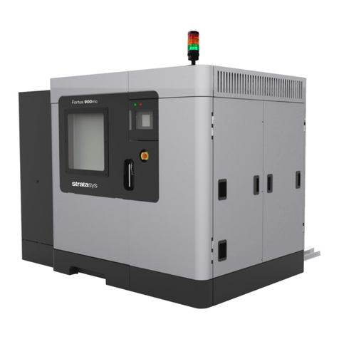
The 3Z Series Model Making System renders high precision, three dimensional (3D) models
from CAD model files. The system consists of all the hardware and software necessary to
fabricate models and prepare them for final processing. Applications program that resides on
the printer provide local control over the model making unit. The operator’s Windows
workstation and support material removal equipment are not included in the system. See Figure
1-1 3Z Model Making System
Figure 1-1 3Z Model Making System
The primary steps of model making with a 3Z Series consist of:
Selecting one or more model files and, from them, preparing a model making job file at
the operator’s workstation.
Transferring the job from the operator’s workstation to the model making system via a
USB flash drive or a local network.
Checking and adding consumables to the model making system as needed. Preparing
the build plate.
Initiating the currently loaded job in the model making system.
Waiting for the job to complete.
Removing the build plate from the system and removing the composite model from the
build plate.
Dewaxing, i.e., removing, the sacrificial (support) material from the model.
Note: Always use the Stylus provided with the printer to touch the front panel
screen.

System Overview
2
1.1 LED Status Indicators
There are four status indicator lights on the 3Z Series model making system. The two on the left
of the touch panel are the Green (Power) indicator and the Blue (Busy) indicator. The two on the
right of the control panel are the Yellow (Caution) and Red (Intervention) indicators. The
indicators can be off, blinking, or steady on. The table in Figure 1-2 shows the status of the
printer as indicated by the LED status indicators.
Power Busy Caution Intervention
Figure 1-2 LED Status Indicators
1.2 Touch Panel
Operator input to a 3Z Series printer is provided through a touch screen. The printer provides
feedback to the operator via the front panel display. 3Z Touch remote runs on any remote,
networked Windows workstation. The remotely operated screen provides the operator with the
exact same look, feel and level of control as the front panel of the printer. However there are
several functions that require close proximity to the system at the time they are performed and,
under normal circumstances, these functions should not be initiated remotely. See Figure 1-3.
Touch screen 3Z Touch Remote
Figure 1-3 3Z TOUCH SCREEN AND REMOTE
CAUTION! The touch panel provides control over several setup and calibration

System Overview 3
functions. Randomly selecting these functions without understanding what they do,
could render the system inoperable until these settings are correctly restored!
The touch panel is divided into 2 sections Status and Command. See Figure 1-4.The icons
above the black line indicate the status of user responsible consumables, the job progress
Indicator bar and the printer Ready/Status indicator. The icons below the black line are used for
initiating commands to the printer.
Figure 1-4 3Z Touch Panel
The Ready/Status Indicator shows the general status of the printer. The descriptions are
illustrated in Figure 1-5. Touching the Ready Status icon will reveal more detailed information if
available.
Figure 1-5 3Z Ready Status Indicator
There are 8 basic activity scenarios that the touch screen may be displaying depending on the
state of the printer. Within these scenarios there may be supporting displays that provide more

System Overview
4
detailed information and operational control. The corresponding Ready/Status indicators are
shown to the right. There is no Ready/Status indicator for Idle.
The 8 basic scenarios are:
1. Initialization - The printer is initializing and resetting hardware and
software components during a reset, power up, or recovery.
2. Idle - The printer has initialized properly and is either ready to print or is waiting for
the build plate and/or file to be loaded.
3. Printing - The printer is in the process of printing a job.
4. Pause - The printer has been paused by the user.
5. Job Complete - Printer has completed the job and the cover has opened.
6. Auto Recovery - The printer is recovering from an abnormal operation.
7. Intervention - The printer has paused and is waiting for assistance
Click on the icon for further information.
8. Standby - The temperatures of the tanks, heated lines and printheads
are set to a lower value.
The Network status icon indicates the connection status between the printer and the network.
The network status is illustrated below
.
1. Printer connected to the network. Available to multiple users.
2. Printer connected to the network with a second user accessing
the printer via 3Z Touch Remote.
3. Printer locked so printer cannot be accessed from the network
(Local control only).
4. Pinter not connected to the network (Local control only).

System Overview 5
1.3 3Z Organizer – 3Z Print – 3Z Works – 3Z Analyzer
There are four separate, Windows based applications programs associated with the 3Z Series
Model Making System and its operation. They are all installed and run on the operator’s
workstation and constitute an integral part of the model making process. Details regarding the
installation and operation of the 3Z Works, 3Z Analyzer, 3Z Print and 3Z Organizer programs
are provided in the 3Z Works User’s Manual, P/N 840202, which is available on the Solidscape
3Z Series Software Flash Drive, P/N 945087
WARNING: Be sure to install 3Z Organizer, 3Z Print, 3ZWorks, and 3Z Analyzer
and from the FLASH DRIVE provided with your new Model Making
System to ensure that the latest versions of software and
configuration files are installed on your PC.
3Z Organizer
The 3Z Organizer is the primary interface between the operator’s workstation and the
3Z Printer. The program is started and then runs invisibly in the background. When an STL,
SLC file or a folder with numerous files are dragged / copied into the 3Z Organizer Queue
folder, the file(s) are automatically retrieved and processed through the printer driver.
3Z Printer Driver
The printer driver appears and functions similar to other windows based printer drivers.
The operator first selects the desired printing parameters and then selects the PRINT
button. The printer driver processes the file and then automatically sends the completed file
to the desired printer or a pre-defined file folder.
3Z Works
3Z Works is a Windows application program that runs on the operator’s workstation. It
allows the operator access to more detailed controls with regard to file preparation. Controls
include positioning and orienting model files and other advanced operations. The resultant
.3zp or .3zs file can then be sent to the printer system via the printer driver or a USB flash
drive. 3Z Works automatically generates all support structures required to build the model.

System Overview
6
3Z Analyzer
3Z Analyzer is a Windows application program that runs on the operator’s workstation. It
permits job file viewing, analysis and correction of the job file for pre-build evaluation, repair
and diagnostic purposes. It also allows the operator to view the job file one ‘slice’ at a time
exactly as it will be printed on the system. This tool is valuable for observing features,
searching for potential defects and identifying anomalies from the 3D CAD process that
appear to represent a unified solid model but in fact have internal seams or voids that will
ultimately result in several separate model pieces or other model defects. Anomalous layers
can be removed or replaced to permit successful model building despite CAD model
defects. Break points can be inserted into job files to permit the system to pause when that
layer has been completed on the 3Z Printer.

Power on Procedure 7
Chapter 2 – Power On Procedure
This section provides complete instructions for preparing the system and initiating a print job.
Careful adherence to preparation is essential to producing good quality models. Failure to
perform, or short cutting, any of the specified procedures may result in a malfunction and
compromise the operation of the system and/or the quality of the models produced.
Job preparation includes both of the procedures listed below when the system is powered off
and, under those conditions, requires approximately eight hours. Under normal conditions, i.e.,
when the system is powered on and at operating temperatures, only the second procedure is
required. Performing the New Job Startup Procedure typically takes a trained operator
approximately five minutes.
1. Pre Power On Procedure Section 2.1
2. Power On Procedure Section 2.2
2.1 Pre Power-On Procedure
This procedure is typically performed only during a new installation or after a system has been
moved or relocated. Step 4 through Step 7 of this procedure must also be performed after the
vacuum filter has been replaced. All references to the ‘unit’ refer to the actual 3Z Series printer.
1. Confirm that the unit is powered off by pressing the ‘0’, side of the power switch on the left
rear corner of the unit.
2. Confirm that the unit power cord is plugged into the unit power entry socket.
3. Confirm that the other end of the unit power cord is plugged into an appropriate power
outlet.
4. Confirm that the vacuum has a clean bag installed.
5. Confirm that one end of the vacuum control cable is plugged into the vacuum switch box.
6. Confirm that the other end of the vacuum control cable is plugged into the printer.
7. Confirm that the vacuum power cord is plugged into the vacuum switch box.
8. Confirm that the vacuum switch box is plugged into an appropriate power outlet
Note: There are several different vacuum configurations associated with the system based
on the local voltage and regulatory requirements. A summary of vacuum
configurations and wiring is provided in Appendix C Vacuums.
2.2 Power-On Procedure
This procedure is performed on every power up and serves as a check to confirm that the unit
and its subsystems initialize correctly.
This manual suits for next models
3
Table of contents


