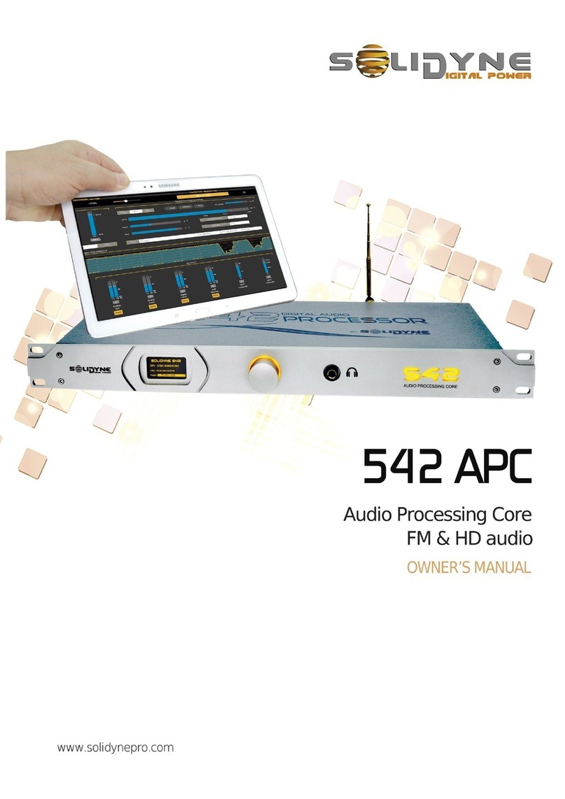
Solidyne 562dsp User manual

5-bands FM digital audio processor
User’s manual
3 de F eb r er o 3 2 5 4 (14 2 9)
B ue n os A ir e s - A r g en t i n a
Phone: + 5 4 11 4 702 0 0 90
e-mail: i nf o@ s ol id yn ep r o.c om
fax: + 5 4 11 470 2 23 7 5
web: w ww . S ol i d yn e P RO . c om
Last revision: May 2011

Página 2 procesador para radiodifusión - SOLIDYNE 562dsp

SOLIDYNE 562dsp EVOLUTION – FM broadcast digital processor Page 3
Contents
About this manual ....................................................... 4
User’s manual 4
562dsp firmware 4
What’s in the box? 4
About the montage 4
ADVICES 4
Chapter 1 Quick installation guide ......................... 5
1 1 Basic connection and settings 5
1 2 Brief diagram for general connections 6
1 3 Understanding the main screen 6
Chapter 2 Advanced installation............................. 9
2 1
Power supply 9
2 2
On mounting 9
2 3 Analogical audio connections 9
2 4 Digital audio connections 10
2 5 Console MICstart 10
2 6 MPX output 10
2 7 RDS Coder (OPTIONAL) 11
2 7 1 RDS – PC connection 11
2 7 2 Connecting to the transmitter 11
2 8 RS-232 remote control 11
2 9
ETHERNET connection (OPTIONAL) 11
2 9 1
Set up 12
2 9 2
Accessing from the LAN 13
2 9 3
Accessing from Internet 14
Chapter 3 Starting up and operation.................... 15
3 1 Basic actions 15
3 1 1
Processing programs 15
3 1 2
Modes of control 15
3 1 3
Using the JOG wheel 15
3 1 4
Access password 15
3 2
INSTALLATION SETTINGS 16
3 2 1 INPUT SETUP 16
3 2 2 OUTPUT SETUP 17
3 2 2 1
Adjusting 100% of modulation in FM 17
3 2 2 2
Notes about FM 17
3 2 3 PROCESSOR SETUP 18
Chapter 4 Audio processing settings .................. 19
4 1
PROGRAM SELECTION 19
4 2
DEFAULT PROGRAMS 19
4 3
USER PROGRAMS 21
4 3 1 COPY PROGRAM 21
4 3 2 EDIT PROGRAMS 21
4 4 PROGRAM ADJUSTMENTS 22
4 4 1 PROGRAM NAME 22
4 4 2 EXPANDER / AGC 22
4 4 2 1 AGC OUT GAIN 22
4 4 2 2 AGC attack time 22
4 4 2 3 AGC recovery time 23
4 4 2 4 Hold 23
4 4 2 5 Expander threshold 23
4 4 3 AUDIO EQ 23
4 4 4 MULTIBAND COMPRESSOR 23
4 4 4 1 Attack times 24
4 4 4 2 Recovery times 24
4 4 5
DENSITY EQUALIZER 24
4 4 6
SRS WOW
®
25
4 4 6 1
SRS TruBass
®
26
4 4 6 2
SRS
®
(3D Enhancement) 27
Chapter 5 Remote Control......................................29
5 2
Installing 29
5 3
Using the software 29
Chapter 6 Audio processing for broadcasting..........31
2 1 A brief history 31
2 2
Solidyne 562dsp psycho acoustic digital processor 33
2 2 1
Blocks diagram 33
2 2 2 24 BITS @ 192 KHZ A/D CONVERTER 33
Digital Input / Resampler 33
2 2 3
PEAK SIMETRIZER 33
2 2 4
SUBSONIC PHILTER 34
2 2 5
LINEAR EXPANDER 34
2 2 6
GATED AGC 35
2 2 7
SRS WOW 35
2 2 8
MULTIBAND COMPRESSOR 35
2 2 9
DENSITY ECUALIZER 36
2 2 10
IM CANCELLED CLIPPER 36
2 2 11
LOW PASS 15 KHz DIGITAL FILTER 37
2 2 12
DIGITAL STEREO CODER 37
2 2 13
MPX PROCESSING 37
Chapter 7 Measurrements......................................39
7 1
MEASURREMENT PROTOCOL 39
7 1 1
Checking the INPUT LEVELS 39
7 1 2
Checking the OUTPUT LEVELS 39
7 1 3
FREQUENCY RESPONSE 39
7 1 4 S/N 39
7 1 5
STEREO CROSTALK 40
7 1 6
DISTORTION 40
7 3
SC100 STEREO CODER Fine calibration protocol 41
7 2 1
TEST POINTS DIAGRAM 41
7 2 2
ADJUST PILOT LEVEL 41
7 2 3
PILOT PHASE ADJUSTMENT 41
7 2 4
CHANNEL SEPARATION 42
7 2 5
MEASUREMENT OF RESIDUAL NOISE 42
7 2 6
AUDIO DISTORTION MEASUREMENTS 42
Chapter 8 Technical specifications ......................43

Page 4
FM broadcast digital processor - SOLIDYNE 562dsp EVOLUTION
About this manual
User’s manual May 5, 2011
562dsp firmware 3.40
All rights reserved. No part of this manual can be
reproduced, be copied or be transmitted in any
form or by no electronic or mechanical procedure:
or in its totality or partly.
What’s in the box?
You must find the following components into the
box.
1 Solidyne 562dsp processor
1 user’s manual
1 AC Interlock
1 CD-ROM with VirtualRack 5 software.
1 Guaranty certificate
4 self-adhesive rubbers tops
Please check when receive to verify that all
components are okay.
About the montage
562dsp processors are designed for rack montage
in standard racks of 19”, requiring 3 rack height
units. If you prefers, the processor can be placed
on a table. Four self-adhesive rubber tops are
given for this purpose.
When mounting, start fitting the bottom screws,
and soon the superior ones. Use flat screws with
flexible o-rings (rubber, PVC, etc.). The frontal
panel is made of aluminum, so you must take
special care of don’t to apply excessive force on
the screws since it can cause deformation or even
break the angles of the panel.
ADVICES
AC
Voltage
The unit cans wok with 110 or 220 VAC.
A voltage switch on the rear panel selects
the correspondent voltage.
ALWAYS CHECK THIS SELECTOR
BEFORE PLUG IN.
In order to reduce the risk of electrical shock, do not retire the
covers of the cabinet. The internal pieces do not require
maintenance of the user. Refer the technical maintenance to
qualified personnel.
The power cord provided with the unit gives
Earth return to the processor. Do not replace it
nor uses adapters.
MAKE SURE THAT HAVE WITH A GOOD
GROUND TAKING.
The exclamation icon within a triangle that
appears in this manual is for alerting to the user
about the presence of important instructions on
the operation and maintenance of the
equipment.
Letter “i” within a circle that appears in this
manual is for alerting to the user about the
information; advices and tips of extreme
importance.

SOLIDYNE 562dsp EVOLUTION – FM broadcast digital processor Page 5
Chapter 1 Quick installation guide
1.1 Basic connection and settings
CONECTIONS
Power supply
Before plug in; check the position of the
AC VOLTAGE selector, on the rear panel
(200-240 V, 50/60Hz; or 100-130 V, accords
to correspond)
Inputs
Analogical audio inputs are balanced, using
XLR (female) connectors Connect the
PROGRAM OUTPUTS of your console to
these inputs Take care of not invert the
phase of the channels
Optionally; the 562dsp has digital AES-3
(AES/EBU) input, for digital consoles or links
This input supports 16/24 bits and sample
rates from 30 up to 96 KH When the digital
input is used, we recommend connecting the
analogical inputs too 562dsp will switch
automatically to these inputs in case of failure
on the AES-3 signal
Outputs
Connects the 562’s MPX output (BNC) to
your transmitter exciter
Power on
The unit has an ON/OFF switch on the rear
panel The main screen Hill show a welcome
splash on start up; and then will load the last
used program
SETTINGS
Controls
All settings values are entered using a
JOG Wheel Turn the JOG to select
options and to change values Pressing
briefly the JOG, confirms an option
Pressing and holding the JOG (around one
second), go to the main menu Each
screen graphically indicates the actions
available with the JOG (see figure)
Input
The default input level is +4 dBu If your
console manages a different level, you
must adjust the processor input level
Press briefly the JOG to enter to the main
menu Choose the option “Setup Input”
and adjust the level according to the
nominal specified on your console
Programs
Your radio already is on the air with the
sound of the Solidyne 562dsp At this
point, you must be anxious to listen what
562dsp is able to do with the sound of your
radio on the air… to begin we will explain
briefly how to select the factory presets
Tunes your radio in a good audio
equipment and do the following:
Turn the JOG. Note on the screen how
the different presets programs names
changes Pressing briefly the wheel load
the program, changing the processing
and the sound on the air
The 15 PRESET PROGRAMS can not be
changed You have 15 USER MEMORIES
to create your own adjustments You can
start copying a preset program to a user
memory, and soon modifying it

Page 6
FM broadcast digital processor - SOLIDYNE 562dsp EVOLUTION
1.2 Brief diagram for general connections
1. If your computer does not have serial
port; you can use a RS232 to USB
adapter to connect the 562dsp on a USB
port.
In units with option RDS, you need to
connect a computer to the processor for
RDS programming. This connection can
be not permanent (in case that a fixed
text is transmitted; it is stored into RDS
memory).
2. When the processor connects to the
console using the digital inputs, it’s
convenient to make the analogical
connection too. In case of fault in the
digital signal, 562dsp changes to the
analogical inputs automatically.
3. In this example a RF connection was
used to transport the MPX signal from
the processor to the transmitter, which
assumes installed in a build far from the
studies.
In other configurations, the processor
locates in the transmitting plant and a
digital link is used to send the audio
(multiple sends can be used for backup).
In this case, the remote control of
562dsp can be implemented through a
data channel of the link that allows
sending RS-232 data.
1.3 Understanding the main screen
Next you will see an overview on the 562dsp main
screens. Later each processing stages and its
settings screens are fully analyzed.
When the unit starts up; the boot screen appears
on both screens showing the current version of the
firmware. Once started, the unit presents the main
screen at the left, and the main menu at the right.
Nextt, the main screen is described briefly as
introduction to the 562dsp graphical environment.
The progressive bars show the action of several
processor stages. The name of the current preset
and state of inputs and outputs also appears on
this screen. From left to right you find:
The input VU meters (L & R). Below the vu-
meters an overload (OVL) warning can appear, if
the input level reach 8 dB before the “digital
clipping” level (@ +18dBm). This warning turns off
last 5 seconds when the “clipping” condition
disappears.
AGC bar shows the action of the Automatic
Gain Control, which fits the input gain so that the
signal arrives at the processing stages with
constant level. If the signal from the console

SOLIDYNE 562dsp EVOLUTION – FM broadcast digital processor Page 7
arrives with low level (or too high), the processor
automatically compensate its input gain so that the
output level is unvarying.
If the input signal falls abruptly, the AGC holds its
current value; to avoid an undesirable effect
known as “breathing”, that appears when the
signal is very low and the AGC compensates their
gain excessively increasing the background noise
in the voice intervals. This feature knows as
Gated-AGC.
In normal operation this indicator will have to work
at middle scale (15 dB)
The following indicators show the action of the
multiband compressor. There are five
compression bands called loudness bands (LF,
M1, M2, HF, SH). These indicators (like the AGC)
show the gain reduction applied to the signal, for
that reason they “grow downwards”.
Band LF corresponds to bass notes of the audio,
below 160 Hertz, M1 and M2 to mid tones and HF
and SH to the highs.
The LOUDNESS concept associates to the
sensation of sonorous power perceived by the
human ear. With no need to exceed the maximum
percentage of modulation fixed by the law, the
processor can obtain that the radio sounds
stronger. The radio with better processing will be
the one that better sounds in the dial.
As will be explained later, another objective of the
processing is to increase the energy in the entire
audio spectrum, to produce the maximum possible
modulation in the RF carrier, which is translated in
greater radiated energy, improving the
transmission reach in marginal areas. For this, the
processor applies a complex procedure of
compression on each audio band, producing
greater sensation of loudness to the ear.
The size of each luminous bar indicates the
compression degree at every moment. Its effects,
obviously, changes according to the different
types of music and voice; but in general can say
that when a band indicator begins to light (values
up to 10 dB) the action is smooth and is totally
accepted by the human ear. With values of 15 dB
or greater will notice a greater “sonorous force”,
being a level of extreme processing.
Another important value to consider is the
recovery time. This is the time that takes a band
in recovering its previous gain. This is evident at
first viewing the indicators. The slower it’s the
recovery, the processing sound soft and the music
sounds natural. However, when they are fast, an
increase of the loudness takes place, but the
sound can becomes more “rough”.
“AES In” indicates if the unit is using the digital
input. It activates just at the moment at which the
digital data enter.
= digital input
= analog input
“MPX Out” indicates that the processor is using
the internal FM stereo coder.
Finally; the screen shows the name and number
of the current program. You can explore the
programs list turning the JOG; but a program is
not active until you load it pressing briefly the
wheel.
A program is a set of values stored in an internal
memory.
You access to the MAIN MENU (the right screen)
by pressing and hold the JOG wheel. From here
you can access to all functions and features of the
processor.

Page 8
FM broadcast digital processor - SOLIDYNE 562dsp EVOLUTION
THIS PAGE INTENTIONALLY LEFT BLANK

SOLIDYNE 562dsp EVOLUTION – FM broadcast digital processor Page 9
Chapter 2
Advanced installation
2.1 Power supply
•The AC voltage variation must stay smaller to
10%. Otherwise, uses an UPS.
Always CHECK the correct position of the
VOLTAGE SELECTOR (200/240 Volts o
100/130 Volts, according to the country)
AC wires do not have to be mixed with audio
wires, especially with analogical ones.
Remember that all audio installation must
have a trustworthy grounding. We
recommend accomplishing with the
effective norms - Article 810 of the National
Electricity Code (NEC); ANSI/NFPA Nº 70-1984 in
USA; IRAM 2379 and 2281-3 in Argentina. This
norm provides information and guidelines for a
consistent grounding.
2.1.2 On mounting
•562dsp can be mounted in a standard rack of
19”; or can be used on a table. Rubber tops
are provided with the unit. Do not place the unit
on unstable surface or shelf; the apparatus
could fall, causing damages to someone and to
be damaged the unit.
•The ambient temperature must stay between
5ºC and 40ºC. Avoid direct solar ray incidence
on the processor or proximity of heat sources.
•The openings and grooves allow the circulation
of forced air impelled by the internal cooler.
These openings do not have to be blocked nor
covered, not to obstruct the refrigeration of the
internal components.
•562dsp has internal protection against RF
fields, which allows locate it next to
transmitters (AM or FM). Avoid strong
electromagnetic fields (power transformers, big
motors, etc).
2.2 Analogical audio connections
Inputs and outputs are electronically balanced.
The inputs are “bridging” type, with impedance
greater than 10 KOhms. The connectors used, as
is standard, are female XLR-3 for the inputs and
male for the outputs.
Take specially care with the phase.
•Use one pair shielded audio cables of GOOD
QUALITY, preferably with double shielding.
The maximum length recommended is 30
meters, although in special cases it is possible
to achieve 100 meters accepting a little loss at
high frequencies.
•The connection of this cables are made as is
standard. See the following table:
Balanced input/output connections:
1 = GND
2 = balanced positive phase (+)
3 = balanced negative phase (-)

Page 10
FM broadcast digital processor - SOLIDYNE 562dsp EVOLUTION
Unbalanced connection:
Inputs: Signal = 2;
Ground = joint 1 and 3
Outputs: Signal to pin 2; leave pin 3 unconnected
Ground = pin 1
2.3 Digital audio connections
Optionally, the processor has digital AES-3
inputs/outputs (models 562dsp/AES).
The digital input supports:
Resolution: 16 - 24 bits
Sample rate: 30 KHz a96 KHz.
Internally 562dsp works at 24 bits/192 KHz, the
digital signal is converted internally by a stage
called “Resampler”.
When the digital input is used, is convenient to
connect the analogical input too. In case of losing
the digital connection, the processor switches
automatically to the analogical inputs. The input
mode is selected from the main menu choosing
the option “Setup Input”, as is explained later.
S/PDIF: you can connect an S/PDIF
output to the AES3 input of 562dsp
using an S/PDIF to AES-3 adapter. The
figure shows a compact adapter XLR
BNC.
AES-3 output has a resolution of 24 bits with a
samplerate selectable between 48/96 KHz (see
“3.2.2 – Output Setup”). The connector is male
XLR.
AES3 input and output cables connect as
following:
XLR Signal
1 GND
2 AES3 (1)
3 AES 3 (2)
AES-3 standard connection
2.4 Console MICstart
With the 562dsp the current processing program
can changes when the study microphones
activates. In this way you can use a processing
specially done for voices. The default adjustment
for voices is the program “09: Voice Impact“.
Obviously; you can copy and customize this
program.
The commutation takes place when grounding the
MICstart input. When this happens the processor
exchanges the program and the access from the
JOG wheel is blocked. When the MICStart input is
opened, 562dsp returns to the previous program.
“Console MICstart” uses an RCA connector. With
consoles Solidyne 2300 series, MICstart is
connected directly to the Digisolid output of a
microphone channel (please refers to the manual
of the console). In other consoles, the control can
be solved using the tally signal to activate a relay.
Connect the relay contact directly to the RCA “MIC
Start”; and the coil in parallel to the tally light.
The relay coil voltage depends on the voltage
gives by the console
When the relay receives tension, the contact is
closed activating the Mic Start function in the
processor. The voice’s program remains active
while the contact is closed.
This feature comes disabled from factory. In
order to use it, you must enable the option “MIC
PROCESSING” in the processor setup (see “3.2.3
- Processor Setup”).
2.4 MPX output
The MPX cable will be a RG-59 (coaxial 75 ohms),
like the used for CATV. The output connector is
BNC type. The maximum length recommended for
this cable is 25 m. Take care with the grounding;
although this rarely is cause of problems because
all Solidyne processors have MPX differential
outputs, that is to say, with the Earth isolated of
the cabinet, to avoid ground loops.
If some residual humming appears when the
system is on the air; power off the processor. If the
humming disappears, check the input connections
at the processor. If, however, the humming
continues (and only disappears unplugging the
MPX cable), this indicates some problem with the
grounding.

SOLIDYNE 562dsp EVOLUTION – FM broadcast digital processor Page 11
When enters to the transmitter through the MPX
input, make sure that the internal preemphasis
network IS DISCONNECTED (that is to say, flat
response from 20 to 100 KHz). Contrary, when
use an external stereo coder, make sure that the
generator INCLUDES the preemphasis curve.
This is thus since the 562dsp audio output DOES
NOT INCLUDE preemphasis (only the MPX output
has preemphasis).
2.6 RDS CODER
(OPTI O NAL)
Models 562dsp/RDS have internal RDS coder.
RDS (Radio Data System) is a system developed
by the European Broadcasters Union (EBU). It
allows adding to a conventional FM transmission,
additional information by means of the inclusion of
sub-carrier that contains data.
Their main applications are:
1. The automatic tuning of the receiver to a radio
network selected by the user, which, allows to listen
to a program, for example Classic Radio, during a
long trip by the route, with no need to tune manually
the receiver to another station of the same radio
network, when the reception happens to be deficient
when leaving the zone on watch of a determined
station.
2. Show on the receiver screen the radio network
name that is tuned, for example Radio 1, and the
kind of program: the general news, talk-show,
sports, music, varieties, monk, etc.
3. The automatic reception of information related to the
traffic. When this feature is selected the news has
priority on the traffic, so that the receiver will
exchange, automatically, within a same network, to
the transmitter that emits information on the traffic,
and once finished this information it will return to be
in tune, automatically, the transmitter that previously
was selected.
2.6.1 RDS – PC connection
For setup and control of RDS stage; the 562’s
“RDS Data” port must be connected to a
computer, using a standard COM (RS-232).
Use a standard crossed
serial cable (as known as
“null-modem”). Two female
DB-9 connectors are
required. The following table
shows the diagram of
connection, although only the
connections emphasized in
bold are needed.
The computer is used to transmit data to RDS
coder. These data can change in real time, like
when the names of the songs are transmitted, or
can be a fixed text that it is stored in the internal
memory of the RDS coder.
In order to command the RDS coder; the software
Solidyne-Magic RDS is required. This application
is included in the 562dsp CD-ROM, provided with
the unit. Using this tool you will be able to start to
send RDS data. Please refer to the RDS help file
for detailed information on the software.
2.6.2 Connecting to the transmitter
The models 562dsp/RDS do not require a special
connection. MPX signal contains the RDS
information that is injected directly to the
transmitter when connecting the MPX output
The digital signal that it contains information RDS,
is transmitted with a speed of 1187,5 bit/s and
modulates a subcarrier of 57 KHz, using the
method of Amplitude Modulation with suppressed
carrier, that is added to the multiplexed
stereophonic signal; that it is sent to the
transmitter input. See the blocks diagram shown in
“Chapter 1”.
2.7 RS 232 remote control
The connector PC CONTROL RS 232 allows to
connect a PC directly to the unit. Using the
software 562dsp VirtualRack you have full control
of the 562dsp. Please refer to “Chapter 5 –
Remote control” to see details on the software.
To conect the 562dsp to the PC use a standard
RS232 serial cable (male-female DB-9).
The computer must have one RS-232 available. If
the computer only has USB ports, a USB to RS-
232 adapter can be used. Make sure to use a
good quality adapter.
2.8 Ethernet connection (OPTIONAL)
RJ-45 Ethernet connector allows connecting the
processor directly to a LAN. The unit can be
controlled via TCP/IP from another PC of the LAN
or via Internet; using the software Solidyne
562dsp VirtualRack. See “Chapter 5 – Remote
Control” for software details.
RDS Data PC
2 (RxD) 3 (TxD)
3 (TxD) 2 (RxD)
4 (DTR) 6 (DSR)
5 (GND) 5 (GND)
6 (DSR) 4 (DTR)
7 (RTS 8 (CTS)
8 (CTS) 7 (RTS)

Page 12
FM broadcast digital processor - SOLIDYNE 562dsp EVOLUTION
2.8.1 Installing and settings
Before see the detailed explanation, an overview
on the settings procedure.
a) Connect the 562dsp to the LAN (Hub, Switch or
Router) using a standard UTP cable.
b) Check the IP address of the unit using “DS
Manager” software (this tool is available into the
folder “IP-Access” in the original CD).
c) A PC will be used to run the software and to access
to the 562dsp hardware. We call to this PC “local
terminal”. Install in the “local terminal” the Solidyne
VirtualRack software, provided with the unit. If there
is a Firewall (by software or hardware) you must
enable port 1101 for the communication with the
562dsp.
d) Install in the “local terminal” the ‘Virtual Serial Port’.
For make this, install the IP-ACCESS pack from
Virtual Rack 562 CD-ROM.
e) Run the VRack5 software, it will explore the first 5
ports to detect the audio processor, if not detected
you must set the port number in the file serial.ini
f) To access from outside to the LAN, please refers to
“2.8.3 –Accessing from Internet”
2.8.2.1 Set up
Connect the 562dsp/IP to the LAN and turn on. Next
to the connector RJ45 a green LED will light. If
amber LED lights then the network detected is of
100Mbps.
From setup CD-ROM install the IP-ACCESS pack,
running \IP-ACCESS\Setup.exe. Once installed, run
‘DS Manager’ tool, which provides in 562dsp/IP CD-
ROM (folder IP-ACCESS). This tool will show all
active units connected to your LAN. Each unit has a
MAC address that is unique and fixed; and an IP
address that you can change freely.
Select the unit from the list and press the button
[Settings]. Here you can define a new IP. In this
example the local area network uses address like
192.168.0.x, to accede from any terminal of that
network to 562dsp/IP you need that IP address is
compatible. Assign a fixed IP that it does not
generate conflicts with another terminal (in the
example 192.168.0.11).
If you have a DHCP server you can obtain a
dynamic IP address, although if IP changes
frequently will require changes in the configuration
of the clients (or in the LAN like for the access
from Internet).
Assign the Gateway address (usually
192.168.0.1), and the subnet mask. This is
needed if you wish to accede to the 562dsp/IP
from outside of the LAN. If you don’t know these
values, contacts to your network administrator.
The port used is 1101. You can change it if
conflicts with another application appear in the
terminal client who uses the same port, but this
rarely occurs.
¡NEVER PRESS THE BUTTON “INITIALIZE”! THIS
OPTION WILL CHANGE CRITICAL VALUES FROM
FACTORY DEFAULTS
Critical default values:
•In the section 'Connection', Transport Protocol
= TCP (default value).
•In the section 'Connection', Inband commands
= 0 (dissabled) (default value).
•In the section 'Serial Port', On the fly
commands = 1 (ennabled) (default value). If
disable it applications can not set the baud rate.
•In the section 'Serial Port', 'DRT Mode = 1
Indicate connection status' (default value). It’s
a critical value. If is changed communication will
fail.

SOLIDYNE 562dsp EVOLUTION – FM broadcast digital processor Page 13
All this values are set from factory. If you have
problems with communication, check these
variables. This values must be used when create
the Virtual Serial Port with VSP Port Manager.
You can make a PING to verify the access to
562dsp/IP hardware from the terminal. Another
option is to use the button [BUZZ] from the main
window of the DS Manager and you will see the
LEDS of connector RJ45 to blink during one
second. If you wish, you can set a password to
block modifications in your settings.
2.8.2 Accessing from the LAN
The client PC must have installed TCP/IP
protocol. If there is a Firewall (software or
hardware) open the port 1101 for the
communication with the 562dsp/IP.
Install the driver `Virtual serial port' that allows to
communicate with the processor. The tool is
‘Connection Wizard', with this you must create a
new serial-port<-> IP address connection.
Virtual serial port must install in each PC from
which it is desired to accede to the 562dsp/IP.
Once installed the virtual serial port it must appear
in the Windows Devices Manager.
Now, double-clic on VSP to check the following
settings:

Page 14
FM broadcast digital processor - SOLIDYNE 562dsp EVOLUTION
•Verificar que el protocolo de transporte sea
TCP.
•Que la opcion 'On-the-fly commands' este
habilitada (modo normal = Out of band).
•Connection mode= Inmediatly.
VirtualRack software automatically explores the
first 5 ports to detect de 562dsp/IP hardware.
If the port number assigned was bigger than Port
5; then you must declare the port manually by
editing the configuration file serial.ini (VirtualRack
folder).
2.8.3 Accessing from Internet
If you want access to a 562dsp/IP located outside
your LAN; there are two possible ways in which
the device can be connected to the network.
The unit is connected directly to Internet: In
this case you must enter the IP address assigned
by the Internet provider (ISP).
The unit is connected in another LAN (with
shared Internet access): In order to accede from
an remote PC to the LAN you must configure the
router of that LAN to redirect the packages
incoming by port 1101 to local IP address
assigned to 562dsp/IP (in our example
192.168.0.11), and redirect also the port 65535.
The following is an illustrative example; the screen
of present configuration depends on your router.
Some routers offer the option `Virtual Server', that
is similar but more outpost than the ‘Port
Forwarding'. Soon you will have to install in your
PC (with ‘Connection Wizard') the virtual serial
port. The IP address here entered is the external
address of the local area network.
In order to know the external IP you must see the
settings information of your router. Now you can
run VirtualRack end user software so that that it
communicates with your 562dsp/IP via Internet.

SOLIDYNE 562dsp - broadcast digital processor Page 15
Chapter 3 Starting up and operation
3.1 Basic actions
3.1.1 Processing programs
562dsp has 15 presets programs and 15 user
memories. Programs from 00 to 14 are programs
made by the engineers of Solidyne, ready to be
on the air. There are different adjustments for
different music’s styles. Each program has a name
that identifies it (Jazz, Rock, Pop, Melodic, etc.)
but the names are only indicatives; all music
styles sounds well with any preset. Processing
programs are described with detail later.
You can customize the programs copying it to the
user banks (15 to 29) and edit them. By default,
user memories are “empty” (strictly speaking with
“flat” processing adjustments). You can create a
new adjustment changing the values of each
parameter on the user memory; or copying a
preset to the user memory (recommended). See
“4.3.1 – Copy programs”
3.1.2 Modes of control
The processor can be controlled of many ways:
a) Can be manually controlled from the frontal
panel.
b) Connecting the unit to a PC, you can create
and edit programs using the 562dsp
VirtualRack software. This software allows to
save the 562’s programs in the Hard Disk (files
.562) that you can send by mail, so that other
radios that you manages share the customized
adjustments. In addition; this software allows
creating a scheduling programming, to
change the processing program at certain
hours from the day. Virtual Rack runs in
background using very few resources. In fact
this software can run on the On-Air computer.
In this modality the programs can be chosen
automatically from the OnAir PC, using the
automation software Solidyne Audicom 7.
This way you can use a specific processing for
each musical style.
c) Models 562dsp/IP allows direct connection
to the LAN. You can run the software
VirtualRack from another terminal to control the
562dsp/IP.
With the apropiate network configuration, you
can adjust the sound of the radio in real time...
from your Laptop, while drinking a cup of
coffee at the living room of your home; listening
you favorite audio system, which sound you
know very well.
By the other hand, this feature allows to asjust
the processing from far distances, to optimize
the reception in areas with marginal coverage.
Please see “2.9 – Ethernet connection”
3.1.3 Using the JOG wheel
All the installation settings and each parameter of
audio processing are managed with the JOG
wheel into a friendly graphic interface.
The frontal panel presents a big blue screen of dot
matrix, and a rotating control (JOG) with push
button. Their use is very simple:
•Turn the JOG control to select an option or to
change values (i.e.: changing levels; select
Yes/No; etc.)
•To confirm an option/value press the JOG
briefly. It’s like make “click” with the mouse.
•Push and hold the JOG by a second to enter
to the Main Menu or to cancel a screen. It’s the
equivalent to double-click with a mouse.
3.1.4 Access password
You can define a password of 3 characters
(letters, numbers and signs) to avoid that non
authorized people make changes on the
programming adjustments.
Each time that you try to access to the main menu
the processor will ask you for the password.
Note that you don’t need the password to
change the current preset on-air. Please see
“3.2.3 - Processor Setup”.

Page 16 SOLIDYNE 562dsp - broadcast digital processor
3.2 INSTALLATION SETTINGS
a) On start up, the 562dsp shows by a few
seconds the boot screen indicating the firmware
version:
Once started; the processor present the main
screen; described in the item 3 of the Chapter 1.
The unit always starts loading the last used
program
b) Pressing and holding the JOG you accede to
the Main Menu of the right screen. Note that a
little arrow appears below “EDIT PGM”.
Once into main menu; turn the JOG until select
the desired option. The selected option is marked
by a little arrow that appears below the icons.
Touch briefly the JOG to confirm the selection.
WARNING
Remember that being in the main screen, turning the
JOG or touching it briefly, you accede to the mode
‘program selection’. In this mode; turning the JOG you
explore the 562’s programs. In order to leave the
‘programs selection’ mode, press and hold the JOG. In
order to accede to the main menu press and hold
again.
If being in the main menu or any settings screen
changes not occur during 10 minutes, the unit returns
to the main screen, discarding the changes.
3.2.1 INPUT SETUP
a) Here you define the audio level and type of
input. The operation on this screen follows the
concept of the previous ones: to select an option
(“Input selection” or “Input level”) turn the JOG and
touch briefly to confirm. Now turn the JOG again
to change the value of the chosen option. Touch
briefly to confirm.
Selecting this option the following screen will
appear:
INPUT SELECTION
Analog: Select this option when the processor
is connected ONLY through the analogical input.
Digital only: Choose this option when the unit
is connected ONLY through AES/3. Also the
analogical inputs can be connected, as back up,
but they will be used only in case that the carrier
of signal AES/3 interrupts. In this case, the
equipment exchanges automatically to the
analogical inputs, being in that mode until the
digital signal is reestablished.
Auto Search: (default) It uses the AES/3 digital
inputs in case of finding a source of digital signal.
Otherwise, uses the analogical inputs. In case of
finding only silence or a total lost of digital AES/3,
the unit switches to the analogical inputs. This
type of faults in signal AES/3 is characteristic
when “a digital data link falls”. As signal AES/3 is
regenerated in the receiver, the digital streaming
follows present, but without content of audio
(channels muted).
Reestablishing the signal in Auto Search
mode: After losing AES/3, or in absence AES
signal, or absence of audio in this digital signal,
the equipment switches automatically to the
analogical mode. The reestablishment to the
digital mode happens in immediately in case
signal AES/3 is had completely lost. Since when
recognizing a valued digital carrier, the processor
quickly returns to use the digital audio like source
of incoming signal. In case the digital signal exists,
but the same one contains silence, the processor
operates as follows: At intervals of 5 minutes the
processor interrupts briefly (1 sec) the audio on
the left channel, connecting in its place the digital
signal of the left channel; verifying soon if the
digital signal were reestablished. If it continues in
absolute silence, then it reestablishes the
analogical signal. This process is repeated time
and time again until as returns signal AES/3.
When the digital audio reappears, the processor
returns to digital mode.
While the digital signal remains absent, the audio
on the left channel is briefly muted at intervals of 5

SOLIDYNE 562dsp - broadcast digital processor Page 17
minutes, to alarm to the engineers of the radio
(and to the operators) that the processor is
working with the analogical backup inputs. This
has been intentionally designing in this way, since
otherwise; an accurate confirmation does not exist
on problems in the signal AES/3.
INPUT LEVEL
Define the nominal level of the input signal. So
that the AGC (automatic gain control) operates
correctly, is very important to fit this level correctly.
This value must agree with the nominal output
level of your console (in the case of Solidyne
consoles this level is + 4 dBm).
NOTE: If you unknown the output level of your console, put the
console’s level at 0 VU peak and reads the level in the
562dsp’s input VU-meters.
With the adequate input level, the AGC works
around 10 to 15 dB of gain reduction. This can be
seen in AGC indicator who will have to indicate 15
dB with strong program signal, lowering to 8 dB or
less when the signal reduces. If the program
signal level abruptly falls, the indication “HOLD”
appears.
Overload warning (OVL): appears in the main
screen when the input signal reaches +10 dBm;
that is to say, +8 dB before the ‘digital clipping'
threshold (placed at +18 dBm). The indication
disappears last 5 sec if the clipping disappears.
The digital input fulfills recommendation AES-K12,
applied to broadcasting, which takes as reference
for 0 VU a digital input level of - 12 dBFS.
This implies 12 dB of headroom. The user cannot
modify the input level when digital input is used.
3.2.2 OUTPUT SETUP
OUTPUT LEVEL: It refers to the analogical output.
Level is fixed at
+4dBm.
DIGITAL OUT: Define the sample rate of the AES-3
output. It can be 96 KHz or 48 KHz.
MPX Level: Define the MPX output level. It can
change from 2V to 5V peak to peak.
You must set the value according to the value that
the transmitter needs to reach the 100% of
modulation (75 KHz deviation).
PRE-EMPHASIS:
Allows to adjust the pre-emphasis
curve according to the regulations of your country
(I.E.: Europe = 50uS; USA, ASIA, Latin-American
=75uS)
3.2.2.1 Adjusting 100% of modulation in FM
For this adjustment use a program material of high
density; with voice and music (i.e.: commercial
spots). Select the program “08:MaxLoudness” (it
produce high output level). Next change the MPX
output level until obtaining 75 KHz of deviation,
measured with a Monitor of Modulation (like the
Solidyne VA16) or with the modulator meter of the
transmitter. For fine adjustment of the 100% you
can use the input gain control of the transmitter’s
exciter.
In the daily use of the processor, probably the
indicators of modulation of needle type overpass
the 100%. This can be due to over-impulses of the
ballistics or to that it responds to values average
of sine wave and the indication is erroneous with
the high processed audio. Please see the
following notes.
3.2.2.2 Notes about FM
Remember that many countries follow the
recommendations on modulation of the FCC
(USA). Recommendation 73268 indicates that the
FM must stay all the high that is possible, but
without exceeding 100% in peaks of frequent
recurrence (“In no case is it to exceed 100 % on
peaks of frequent recurrence”). This indicates that
in transitory peaks (and no frequent) 100% of
modulation can be surpassed staying within the
legal frame.
The 562dsp processor is designed to fulfill this
FCC Norm, being allowed to surpass 100% in no
recurrent peaks slightly. When fitting the
modulation, verifies the norms of its country.
When making the programs; take in count if there
is an UNIQUE program for the whole day. In that
case commitment solutions will be use to accept
all types of voices and music that the Radio emits.
Using the remote control from PC, diverse
programs can be created. This eliminates the
commitments, so each program will be the optimal
for that type of music or voice. In addition, this
automation eliminates the listener’s ear fatigue
associate with the radio stations that use rigid
processors.

Page 18 SOLIDYNE 562dsp - broadcast digital processor
3.2.3 PROCESSOR SETUP
MIC PROCESSING PGM:
MICstart input allows to
change the processing program when the operator
activates the microphones at the console, applying
a specific processing to obtain high impact voices.
This is a very useful feature, since it’s not possible
to obtain an adjustment that sounds optimal for
music and voice simultaneously; for being two
audio signals morphologically different. The attack
and recovery times of the AGC differ sensibly for
both cases; and must be carefully fit to avoid that
its action is audible.
This option is disabled from factory (program
30:Mic processing off). In order to enable it, select
“Mic processing PGM” and choose a program
created for voices (for example 09:VOICE
IMPACT).
The commutation controls from a connector in the
rear panel, detailed in the installation chapter (see
“2,5 Console MIC Start”).
TIPS
The programs for “music” and “voice” do not have to be
radically different. The gains of the density EQ and the
AGC output must stay without greater variations. The
differences will be fundamentally in the attack and recovery
times of the AGC and the multiband compressor.
It agrees to create the adjustment for voices starting from
the adjustment chosen for music. The attack and recovery
times used for music usually are slower than those required
for the voices, mainly in the AGC. Observe and compare the
factory presets.
PASSWORD: You can define a password to avoid
the access of unauthorized personnel to the main
menu to change the settings. Once defined,
562dsp will ask for the password whenever you try
to accede to the main menu, but you don’t need
the password to explore the program list and
change the program on-air.
The password must have 3 characters. Any
combination of letters, numbers and symbols can
be used.
•To enter a password, go to field “Password” turning
the JOG and touch it briefly to confirm.
•A flashing cursor appears to enter the first character.
Turn the JOG until reach the wanted symbol and
confirm with brief touch. The cursor will jump to the
next character.
•Proceed in the same way to choose the others
characters.
•After confirm the last character, the option “OK” is
on focus. PRESS AND HOLD to confirm the
password. A brief touch in this point will make jump
the cursor to the first character again.
•Press and hold the JOG cancels the process in
any instance (equivalent to escape), except when
“OK” is selected, in such case confirm the
password!
•To delete the password, edit it entering 3 space
characters.
Write down the password in a secure place, in
order to do not loose it If you forgot the
password, please contact with you Solidyne
dealer
PROCESSOR MODE:
Shows the processor type.
The unit can be prepared for FM or AM stations.
This is defined in factory, because requires some
internal changes in the circuit board; as well as a
different programming of the flash memory with
the corresponding constants for the AM band.

SOLIDYNE 562dsp – broadcast digital processor Page 19
Chapter 4 Audio processing settings
4.1 PROGRAM SELECTION
The unit has 15 default programs (00 to 14) and
15 user memories.
The programs selects from the main screen. Turn
the JOG to explore the list and touch briefly to put
a preset on the air.
•Note that, while you explore the programs, over the program
name appears the navigation instructions.
•While these instructions are on screen, you are in the mode
“exploring programs”.
•Selecting a program this legend disappears.
•Touch and hold the JOG to cancel the exploration. The name
of the current on-air program returns on screen.
CHANGES WILL TAKE EFFECT WHEN YOU
CONFIRM A PRESET PUSHING THE JOG.
4.2 DEFAULT PROGRAMS
562dsp has 15 programs created by the Solidyne
engineers. Next each preset is explained. These
adjustments are the base for the creation of new
programs. Please refer to “4.3 – User programs”
for details about each processing stage.
00: JAZZ – CLASSIC (orchestral)
This is a “soft” program. It was carefully created with the
objective of produce the minimum changes to the original
equalization and balance of the orchestra; maintaining the
dynamic expression; by all means: within the limits of the FM
transmission. For this the AGC uses slow attack and recovery
times, and its output level is around 2 dB, to avoid excessive
compression. Remember that an excessive compression will
cause a spectral imbalance unacceptable for Jazz music and
orchestral assembles.
The times for the bands M1 and M2 require special attention,
since there is much participation of soloist’s instruments in this
music. The recovery times must be similarities, otherwise
timbre modulations will take place, mainly in wind joints.
This adjustment reinforces the lows subtly. The dynamics of
the bass stays using slow recovery time for the low band (LF).
The high frequencies are not emphasized. The objective was
to prioritize the fidelity; “clearness” and definition of the
instruments over the “brightness effect”. By such reason the
recovery time of the high band (HI) is relatively slow. Consider
that the listener always can boost trebles in his tuner by
equalization.
This program also is very appropriate for TANGO orchestras,
although generally the tango tolerates a little more processing
(AGC OUT = 4 dB) and can require adjustments in the times of
the bands of M1 and M2, by the stylistic differences in the use
of the vocal intervention respect to the Jazz.
Respect to the voices, this preset will not produce high impact
voices, since it woks with low compression range. But
remember that you can use an special preset for the voices
(with higher processing).
01: 3D SPACE
It’s similar to the previous one; but a little more “strong” (slower
attack times and faster recovery times). This preset uses SRS
WOW processing to improve the stereo image. Values are 7.7
dB of 3D Width and 3 dB of TruBass (cutoff 50 Hz) obtaining
deeper basses. Control “Focus” stays disabled.
This processing works very well with Jazz-POP, country and
blues, folklore, world music, and tango.
02: TruBASS
This is a general purpose preset, with bass boost. This is a soft
preset, since the basses are reinforced not only with TruBass
and increasing the LF band in the density equalizer, but also
lowers the level of other bands. This is because if you attempts
to give prominence to the lows only enhance the band will
cause excessive compression will not achieve defined basses.
03: MELODIC
Here was prioritized the human voice over the musical support.
To respect the “color” and shades of the soloists was the
central objective when creating this program. As reference was
used material of diverse soloists of ballads, boleros and
melodic music. Although this adjustment is centered in the
voice, is not equivalent to adjustment “VOICE IMPACT”, since
the characteristics of the sung voice differs remarkably from
the spoken voice.
The multiband processing is moderate. The AGC output is
about 3.6 dB. Greater values will cause very audible changes
of timbre in some soloists, due to the imbalance that take place
between the bands with excessive compression. The attack
and recovery times stay relatively slow, not to lose the dynamic
profiles completely.
The mid bands M1 and M2, where the vocal energy is
concentrated, apply a considerable compression to the voice,
since their attack times are fast (37 and 17 mS) and their
recovery times are slow (460 mS and 206 mS respectively).
SRS WOW improves the stereo image (6 dB), boost the highs
(Focus 30º) and reinforce the lows (3.9 dB with cut at 50 Hz).
This achieves a consistent sound and high sonority despite
being a moderate adjustment.
The adjustments of the density EQ compensate the balance
between bands to obtain a flat response, comparing the
processed material with the original one. For that reason band
M1, that is the one that receives greater compression in
average, is emphasized not to lose presence the mid-low.
04: MELODIC LOUD
This adjustment is similar to the previous one, but a little
“hardest”. The output level of the AGC was increased to 6.4
dB. Another radical difference respect to “Melodic” is SRS
WOW. TruBass applies a little reinforcement to de lows (2.6 dB

20 SOLIDYNE ORION 462 MKII
with cut at 40 Hz), supported by a lower attack time for LF
band (22 mS). There is no 3D effect.
05: R&P SOFT 06: R&P MID 07: R&P LOUD
These adjustments were made on Rock & Pop music. They
differ not only in the loudness; are three settings with different
sounds. Obviously, "Soft" is a smoother adjustment that
"Loud." The gain of AGC is 5 dB, 6.4 dB and 7.1 dB
respectively. But the “force” of this presets is sustained not only
by the AGC output level, but also by the fact that all the bands
have slow attack times and fast recovery times. By such
reason, the fifth band of highs post-processing will have
noticeable incidence on the processing.
When all bands have fast recovery times; the action of the
attack times prints “force” to the sound, given “punch” to the
music. This is because being fast the recovery, the next
impulse finds “released” the compressor, and this will take time
again in containing the signal; which lasts the attack time. This
effect is more notable in LF, and as it is explained in the POP
adjustment, one of the keys to obtain forceful “pumping” bass
drums (or beats for techno music).
The balance between bands in the Density EQ differs in the
three cases, giving different color to the sound. Highs are not
boosted to avoid the ear fatigue produced by the electrical
guitars, which can present high distortion (intentionally applied,
of course) whose density in bands M2 and HF usually is
critical. Remember that the previous compression stages are of
“hard” processing.
The low band is freed to obtain great impact in the beats,
essentially in R&P Mid. This is obtained with a slow attack time
(43 mS) and a fast recovery (540 mS). In this way, as the
recovery of the compressor is fast, each beat of big drum is
affected by the attack time, that lets pass the initial impulse of
the wave. This impulse that “escapes” is contained soon by
other stages of the processor (limiters). But the result is a
sensation of greater dynamic range. If the recovery time for the
band LF is slow, the attacks of the successive beats would be
“squashed” by the compressor (the attack acts only on the first
beat and never more, which is equivalent to have an attack
time equal to zero).
The high bands also are something released in preset “Mid”, to
obtain “brightness” and presence in trebles, something of
extreme importance in POP music (usually strident, cheers and
“up”).
08: LATINO-SALSA
This adjustment was thought for music with strong presence of
Indo-afro-Latin-American percussion. By such reason, the
attack of the mid band “M2” was freed and, in smaller
proportion, the high band (approximately 14 mS and 17 mS
respectively). This increases the presence of that bands, in
which great part of the spectral components is concentrated
that contribute to “definition” and “brightness” to the
instruments before mentioned. The effect reinforces with a
fastest recovery in the high band (50 mS).
The attack for the low band is also something fast (18 mS)
whereas its recovery is of the order of 1/2 second. The
objective is to obtain basses with great “height” but without
affect the attack, of vital importance in these rhythms, since
many times the bass is who takes the cadence of the song.
This adjustment can be considered a “moderate” processing,
since the AGC output AGC is fit around 5 dB.
This adjustment is very appropriate also for Son, Salsa and its
derivates.
09: REGGAE
This is a moderate preset with great dynamics and good
loudness. It combines slow attack times with low Density EQ
levels. This combination achieves preserve much of the initial
attack of the instruments, increasing the perception of dynamic
and the "depth" of sound. This is achieved at the expense of a
little decrease of loudness (by the low levels at the equalizer
density), but that is not criticism due to the enhancement of
dynamic range. Uses fast recovery times to compensate for the
density.
10: CHILL-OUT
This can be considered a “moderate” processing. “Chill-out”
makes reference to a calm music, generally of electronic
instrumentation.
By the nature of this music, the commitment with the spectral
balance is not capital, that is to say, there is more freedom to
make the adjustments. In this case was chosen to emphasize a
little the lows and the highs presence. This last one is obtained
making fast (60 mS) the recovery of the high band, whereas
the attack of this band adjusts a little slow (20 mS). This
causes that enters in action the fifth band of high frequency
post-processing (HF). The “weight” in the basses obtained with
a fast attack and a slow recovery in the low band and
increasing the gain of this band in the density EQ.
Respect to the AGC, the output level is located about 5 dB,
with slow attack and recovery times.
This adjustment also is useful for “new age music”. Although
these styles are stylistically different, share the use of synthetic
atmospheres and moderate to slow tempo.
11: MAX BRIGHTNESS
Based on MAX LOUDNESS preset, this program makes a high
boosting of high frequencies, obtaining a great loudness with
remarkable brightness.
HOW MUCH TREBLES?
If you want to prioritize sound quality on the air over the
"impact" that produces the high sonority and extreme
brightness (at the expense of fidelity), we recommend you:
do not transmit with excessive emphasis on high
frquencies.
Remember that the listener can always equalize (boost)
the trebles in his receiver. And indeed he will. If the station
transmits moderate trebles but "clean", without over-
processing, the listener may equalize getting good trebles;
clean and defined.
You can achieve high brightness settings using slow attack
(> 10 ms) and fast recovery times (<60 mS) at HF band,
which means over-process high frequency signals (extreme
limitation and some distortion added by the compressor
acting fast). If the station transmits a very emphasized
sound, when the listener boost HF in his receiver will get
very high trebles, but harshness with low definition that will
cause greater fatigue hearing.
12: MAX LOUDNESS
This it is the more radical adjustment. As the name of the
program suggests, the primary target was to obtain a great
loudness on the air (and improved reach of the FM), leaving in
background the “clarity” of the sound and the spectral balance.
Table of contents
Other Solidyne Computer Hardware manuals