SoliTek Standard 285W P.60 User manual

SoliTek Standard Photovoltaic module
(PV) Documentation and Installation
Manual
SoliTek Standard Photovoltaic Modules
Please read carefully the following product documentation and safety instructions.
Non-compliance with these instructions may void the module warranty.
1. Purpose of this documentation
This guide contains basic information regarding JSC “Soli Tek Cells”standard photovoltaic modules, their
installation and safe handling. All instructions should be read and understood before attempting
installation. If there are any questions, please contact your dealer or JSC “Soli Tek Cells” for further
information.
This documentation refers to the PV-modules themselves and is not meant to be a complete installation
manual for personnel not specifically trained to PV-modules. It serves as a general but strictly mandatory
to the Installer reference. Infringement or inaccurate observance of any clause of this documentation
voids the warranty.
Generally, the installer must conform to all safety precautions in this documentation, as well as the
applicable national codes and standards when installing PV-modules. Before installing a solar photovoltaic
system, the installer should become familiar with the mechanical and electrical requirements for
photovoltaic systems. Keep this documentation in a safe place for future reference.
2. System components (modules and mounting system; standard scope of delivery)
SoliTek Standard photovoltaic modules (type designation Standard xxxW P(M).60, where xxx
stands for nominal power values up to 300 Wp), IEC 61215ed. 2 and IEC61730 certified framed
glass/foil laminates with crystalline solar cells, permanently attached junction box, and double
insulated 4mm² wires terminated in touch safe specific PV DC-connectors.
The mounting system does not form part of JSC “Soli Tek Cells” supply.
3. General safety relevant aspects
Do not attempt to disassemble the module, and do not remove any attached nameplates or
components. Doing so will void the warranty.
The modules are qualified for application class A: Hazardous voltage (IEC 61730: higher than 50V
DC; EN 61730: higher than 120V), hazardous power applications (higher than 240W) where
general contact access is anticipated.

Installing solar photovoltaic systems requires specialized skills and knowledge. It should be
performed only by qualified and specially instructed personnel. The installer assumes all risk of
injury, including risk of electric shock.
Use only equipment, connectors, wiring and mounting hardware specifically designed for use in
a photovoltaic system.
System has to be designed taking into account that the panels are fire clas C rated according to
IEC 61730 standard.
3.1. Precautions for mechanical installation
Standard modules are designed for installation with specific photovoltaic mounting systems.
Other use lies within the full responsibility of the installer. If the Installer is not fully aware that
other mounting system that is intended to be used will be fully applicable to JSC Soli Tek cells
modules, the Installer before the installation can contact the Manufacturer for his opinion in
written form. Manufacturer represented by director can express his opinion if the intended
solution is applicable. However, the full responsibility for usage of mounting systems different in
any form than described in chapter 4 is covered by the Installer and it will void the Warranty.
Manufacturer can decide to extend this Warranty for modules used with other mounting systems
than described in chapter 4, if the Installer provides:
oPositive calculation and test results from laboratory certified according to IEC 17025 of
modules including mounting system mechanical loading according to standard IEC
61215.
oMechanical loading test protocol according to IEC 61215 from independent laboratory
certified according to IEC 17025 of intended to use mounting system with identical to
ordered module.
Extension of Warranty for modules used with other mounting systems that described in chapter 4 must
be written and signed by the director of JSC Soli Tek cells.
Manufacturer reserves a right not to extend Warranty without any major arguments if the Installer will
use mounting solution different than described in chapter 4.
The mounting system must be capable of securely fixing modules exposed to uplift or load
pressures of more than 2’400 Pa.
The mounting structure and hardware must be made of durable, corrosion- and UV-resistant
material.
Observe all instructions and safety precautions included with the mounting system to be used
with the module.
If modules are installed on roofs (non-integral modules or panels), a fireproof underlay is needed.
If modules are installed in roofs, all applicable local, regional and national codes and regulations
have to be observed.
3.2. Precautions for electrical installation
Before any manipulation at an installed PV plant, switch it of first on AC-side after on DC-side of
the inverter or the charge controller.
When disconnecting wires connected to a photovoltaic module that is exposed to light, an
electric arc may occur. Arcs can cause burns, start fires or otherwise create safety (up to lethal
electric shock) problems.
Check for remaining voltage before starting, and observe the local safety relevant regulations for
such working conditions.
Under normal conditions, a photovoltaic module can produce more current and/or voltage (here:
30V DC) than reported at standard test conditions.

Accordingly, the values of ISC and VOC marked on this module should be multiplied by a factor
of 1,25 when determining component voltage ratings, conductor current ratings, fuse sizes, and
size of controls connected to the PV output. In the USA, refer to Section 690-8 of the National
Electrical Code (NEC) for an additional multiplying factor of 125 percent (80 percent de-rating)
which may be applicable.
Contact with a DC voltage of 30 V or more is potentially hazardous. Exercise caution when wiring
or handling modules exposed to sunlight.
Only connect modules with the same rated output current in series. If modules are connected in
series, the total voltage is equal to the sum of the individual module voltages.
Only connect modules or series combinations of modules with the same voltage in parallel. If
modules are connected in parallel, the total current is equal to the sum of individual module or
series combination currents.
Always use the same type of module within a particular photovoltaic system.
With a serial interconnection of the modules, the sum of the open circuit voltage at Standard
Test Conditions (Voc @ STC) must not pass over the maximal system voltage indicated, both
indicated in the modules datasheet.
If the sum of short circuit currents of the parallel connected modules passes over the reverse
current (indicated in the table of chapter 8), string diodes or fuses have to be used in each string
of modules connected in parallel. These string diodes or fuses have to be qualified for the
maximum expected current and voltage. Maximum rating for series fuse has to be 15 A and diode
12 A.
Observe the instructions and safety precautions for all other components used in the system,
including wiring and cables, connectors, DC-breakers, inverters, etc.
Use appropriate safety equipment (insulated tools, dielectric gloves and shoes, etc) approved for
use on electrical installations.
3.3. General prescriptions for installation
Do not apply paint or adhesive to the modules.
Do not use mirrors or other hardware to artificially concentrate sunlight on the module.
When installing modules, observe all applicable local, regional and national codes and
regulations. Obtain a building and/or electrical permit where required.
Keep children well away from the system while transporting and installing mechanical and
electrical components.
Do not wear metallic rings, watchbands, ear, nose, or lip rings or other metallic devices while
installing or troubleshooting photovoltaic systems.
Do not drill holes in the glass surface of the module. Doing so will destroy the module and void
the warranty.
Do not drill additional mounting holes in the module frame. Doing so will void the warranty.
Do not lift the module by grasping the module's junction box or electrical leads.
Do not apply paint or adhesive to the module.
Do not stand or step on module. Danger of breaking the glass or slipping off with possibility of
severe injury or death!
Do not drop the module or allow objects to fall on the module.
Do not place any heavy objects on the module.
Inappropriate transportation and installation may damage the module glass or the solar cells
inside the module.
If module frame is with film, remove it before installation.

4. Mechanical Installation
4.1. Robustness of modules and mounting system
Modules have been tested to withstand snow and wind loads of up to 1 600 Pa. The tests were conducted
with a static load for one hour. This value includes safety factor of 1.5, which means that maximum
mechanical pressure and suction of the panels is 2400 Pa.
The whole support structure needs to be strong enough to cope with above loads.
Load calculations to check for the applicability for the actual installation are within the responsibility of
the system planner or installer.
Any damage to the modules done due to the load miscalculations of the system planner or installer is not
within the scope of warranty.
4.2. Selecting the location
Select only suitable locations for installation of the modules.
In most cases, optimum performance is achieved if the modules face true south in northern
latitudes and true north in southern latitudes.
For detailed information on optimal module orientation, refer to standard solar photovoltaic
installation guides or a reputable solar installer or systems integrator.
The module should not be shaded at any time of the day.
Do not install the module near equipment or in locations where flammable gases can be
generated or collected.
Any damage to the modules done due to the wrong pick of the location for installation of the
modules is not within the scope of warranty.
4.3. Mounting methods
4.3.1. Mounting with bolts
The module must be attached and supported by four M8 stainless steel bolts through the
indicated mounting holes (Figure 1). Torque on the clamp bolt has to be in range of 8-10 Nm.
If additional mounting points are required depending on the local wind and snow loads then
mounting solution with clamping hardware has to be chosen.
Figure 1. Mounting using bolts.

4.3.2. Mounting with clamping hardware
If module clamps are used to secure the module, the torque on the clamp bolt has to be in range
of 8-10 Nm (Figure 2).
A minimum of four module clamps should be used, two on each long frame side, in the general
clamping areas denoted by the wide arrows on the drawing (Figure 3).
Depending on the local wind and snow loads, additional module clamps may be required.
4.3.3. Other
Other specific photovoltaic mounting methods are acceptable as long as they:
oMeet minimum requirements as described in chapter 4.1
oMeet requirements for other mounting systems usage as described in chapter 3.1.1
Figure 2. Mounting using clamps.
Figure 3. Dimensions of the module
In figure 3 1600 Pa corresponds to wind and snow loadings.
Any responsibility for inspection if additional mounting points and/or module clamps are required due to
the local wind and snow loads or due to the particular features of mounting system or its parts lies within
the installer.
Any damage to the modules done due to the lack of mounting points and/or module clamps or wrong
placement of them is not within the scope of warranty.
5. Electrical Installation
5.1. Grounding
All module frames must be properly grounded. Observe all local electric codes and regulations.
A bolted connection is required, it incorporates:
oA screw size of M4 or greater;
oA star washer under the screw head or a serrated screw must penetrate nonconductive
coatings like anodized frame;
oScrew and star washer has to be made of stainless steel;
oGrounding screw has to go through all the connecting elements and protrude outside
by two threads.
Devices listed and identified for grounding metallic frames of PV modules are permitted to
ground the exposed metallic frames of the module to grounded mounting structures.
Functional grounding is not foreseen for the modules. If it is performed, local electric codes and
regulations have to be observed and used grounding means have to be isolated from live parts
by reinforced insulation.
In any case the grounding screws or other parts have to be used separately from mounting parts
of the module.
Grounding resistance of grounding structure shall be reached according to local regulations,
Eurocodes or other legal normative references.
5.2. General electrical installation
WARNING! Electrical shock hazard! Do not touch bare conductors or other potentially energized parts.
Photovoltaic modules convert light energy to direct-current electrical energy. They are designed
for outdoor use.
Do not use modules of different configurations in the same system.
Modules are supplied with IEC certified cables and connectors for serial electrical connections.
Use only additional cables which are qualified for the expected maximum current, maximum
voltage and environmental conditions. Minimum cross section 4 mm2 (#12 AWG) (5,2 mm
diameter with insulation layers cable). Conductor have to withstand temperature variations from
-40 to +90°C.
The PV-DC-connectors must never be disconnected under load! Stick to the first rule of chapter
3.2.
Refer to the relevant standards in your country to determine over current, conductor ampacity
and size requirements.
For best performance, ensure that positive and negative DC wires run closely together avoiding
loops, which will also reduce the strength of inductive impacts of nearby lightning strikes.
Following the installation of a module string, its performance is checked to ensure proper
functioning. At least, ISC and VOC need to be checked with appropriate equipment and circuit
breakers.

6. Lightning protection
For safe operation of PV modules proper lightning protection equipment has to be installed.
Lightning protection has to be achieved by passive Franklin grounding rods installed in a location
of solar power plant.
Please make sure that lightning sphere will not reach PV modules, mounting system, inverters or
other parts. Radius of sphere has to be selected according to local regulations, Eurocodes or
other legal normative references.
Lightening protection equipment has to be directly connected to grounding structure. Grounding
resistance of grounding structure shall be reached according to local regulations, Eurocodes or
other legal normative references.
7. Maintenance
JSC “Soli Tek Cells” recommends the following maintenance items to ensure optimum performance of the
module:
Clean the glass surface of the modules as necessary. Use water and a soft sponge or cloth for
cleaning. A mild, non-abrasive cleaning agent can be used if necessary. Do not use dishwasher
detergent.
Electrical and mechanical connections and the general condition of an installed PV-system should
be checked periodically by qualified personnel to verify that they are clean, secure and
undamaged.
Eventually occurring problems must only be investigated by qualified personnel.
Observe also the maintenance instructions for all other components used in the system.
8. Shutting down the system
Disconnect system from all power sources in accordance with instructions for all other
components used in the system.
The PV-DC-connectors must never be disconnected under load! Use switches designed for being
disconnected under the prevailing DC-load or stick to the first rule of chapter 3.2.
The system should now be out of operation and can be dismantled. In doing so, observe all safety
instructions as applicable to installation.
9. Typical electrical ratings of the concerned modules:
Parameters
Standard
285W
P.60
Standard
300W
M.60
Maximum Power at STC (PMPP) 285 Wp 300 Wp
Maximum power at NMOT (PMPP) 213.65 W -
Maximum power point voltage at
STC (VMPP) 32.94 V 32.15 V
Maximum power point voltage at
NMOT (VMPP) 30.39 V -
Maximum power point current at
STC (IMPP) 8.73 A 9.35 A
Maximum power point current at
NMOT (IMPP) 7.03 A -
Open Circuit voltage at STC (VOC) 39.24 V 39.45 V
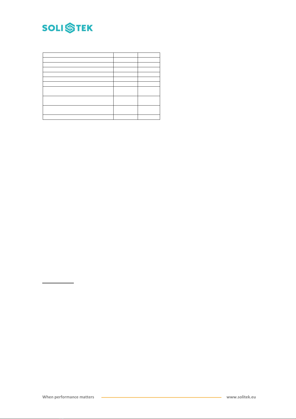
The electrical characteristics are within ±5 % of the indicated values of ISC, VOC, and PMPP under Standard
Test Conditions (irradiance of 1000 W/m2, AM 1.5 spectrum, and a cell temperature of 25°C / 77°F).
10. Disclaimer of liability
Because the use of this documentation and the conditions or methods of installation, operation, use and
maintenance of photovoltaic products are beyond JSC “Soli Tek Cells” control, JSC “Soli Tek Cells” does
not accept responsibility and expressly disclaims liability for loss, damage, or expense arising out of or in
any way connected with such installation, operation, use or maintenance. No responsibility is assumed by
JSC “Soli Tek Cells” for any infringement of patents or other rights of third parties, which may result from
use of the PV product. No license is granted by implication or otherwise under any patent or patent rights.
The information in this documentation is based on JSC “Soli Tek Cells” knowledge and experience and is
believed to be reliable, but such information including product specification (without limitations) and
suggestions does not constitute a warranty, expressed or implied. JSC “Soli Tek Cells” reserves the right
to change the manual, the product, the specifications, or product information sheets without prior notice.
Information about manufacturer:
JSC “Soli Tek Cells””
Mokslininku str. 6A
LT-08412 Vilnius
Tel: +370 52 63 8774
www.solitek.eu
Please consult your dealer or the manufacturer concerning the warranty of your modules. If you have any
further questions, your dealer will gladly assist you.
Open Circuit voltage at NMOT (VOC) 36.99 V -
Short Circuit current at STC (ISC) 9.26 A 9.9 A
Short Circuit current at NMOT(ISC) 7,6 A -
Maximum System Voltage 1’000 V 1’000 V
Fire Class (IEC 61730) C C
NMOT, °C 41,19 -
Maximum reverse current 12 A 12 A
Current temperature coefficient α
[%/°C] 0,03 -
Voltage temperature coefficient β
[%/°C] -0,22 -
Power temperature coefficient δ
[%/°C] -0,32 -
Low irradiance (200 w/m²) power, W 53,11 -
This manual suits for next models
1
Table of contents
Other SoliTek Control Unit manuals

Popular Control Unit manuals by other brands

Hi-Force
Hi-Force HFV66 Operating instructions manual

75F
75F SMART DAMPER Installation & operation instructions

Stone
Stone STWA043WT-01 Equipment manual

Keysight Technologies
Keysight Technologies 8494 Operating and service manual

FlexRadio Systems
FlexRadio Systems FlexControl quick start guide

A-T Controls
A-T Controls TRIAC 20 Series Installation & maintenance manual


