Hi-Force HFV66 Instruction Manual

Operating Instruction Manual:
OM-HFV66-01
From Serial Number:
ALL
1
OPERATING INSTRUCTION MANUAL
HFV66 | MANUAL CHECK VALVE
Hi-Force HFV66 control valves are designed to provide precise control of the hydraulic system flow during
load lowering. The HFV66 Manual check valve features a pressure relief valve that is factory set to 800-
850 BAR (11600-12300 PSI) to prevent cylinder overload.
This ‘original instructions’ document assumes that the operator carrying out any operation with this
product is trained and competent to do so. This manual does not attempt to cover all details or variations
in the equipment. Nor does this manual claim to provide for every possible contingency met in connection
with the installation, operation, or maintenance thereof. Should further information be desired, or should
a particular problem arise which is not covered in sufficient detail, the matter should be referred to
Hi
-
Force.

Operating Instruction Manual:
OM-HFV66-01
From Serial Number:
ALL
2
Table of Contents
1.0 Inspection upon Receipt ......................................................................................... 2
2.0 Safety Precautions .................................................................................................. 3
2.1 Introduction ........................................................................................................ 3
2.2 Work Area Safety ................................................................................................ 3
2.3 General Hydraulic System Safety Precautions ................................................. 3
2.4 Manual Check Valve Specific Safety Precautions ............................................ 5
3.0 Declaration of Incorporation / Conformity ............................................................ 5
4.0 Component Identification ....................................................................................... 6
5.0 Setup and Operation ............................................................................................... 7
6.0 System Diagram of HFV66 ...................................................................................... 7
7.0 Troubleshooting ...................................................................................................... 8
8.0 Contact Details ........................................................................................................ 9
1.0 Inspection upon Receipt
Upon receipt of the product, visually inspect the item for any evidence of shipping damage. Please note:
the warranty does not cover shipping damage. Notify the courier immediately if shipping damage is found
and refrain from putting the product into service. The carrier is responsible for repair and replacement costs
resulting from damage that occurred in transit.
NOTE: Images contained within this document are for illustrative purposes ONLY.

Operating Instruction Manual:
OM-HFV66-01
From Serial Number:
ALL
3
2.0 Safety Precautions
2.1 Introduction
Read and follow all the instructions and safety warnings carefully before handling, installation, or
use of any hydraulic equipment. Failure to do so could lead to equipment damage, equipment
failure, personal injury or even death. Hi-Force will not be held responsible for any damage to the
equipment, injury or death resulting from the unsafe use of, lack of maintenance to, or incorrect operation
of the product. If in doubt on the correct use of any Hi-Force equipment, contact your nearest Hi-Force office
or distributor. Only qualified personnel should be allowed to operate hydraulic equipment. If an operator has
not been trained on high-pressure hydraulic equipment and its safe usage, consult your local Hi-Force sales
office or distributor who can offer training courses for operators.
2.2 Work Area Safety
Keep work areas clean and well lit. Cluttered spaces and inadequate lighting can result in
unnecessary accidents.
Keep unauthorised persons at a safe distance from the task site.
NEVER use the tools in the presence of inflammable liquids, gases, or material.
DO NOT use the tools in potentially explosive atmospheres (ATEX) this tool is NOT ATEX approved.
2.3 General Hydraulic System Safety Precautions
Failure to observe and obey the following safety precautions could result
in property damage, significant personal injury or death;
When operating any hydraulic equipment, all operators should ensure that all necessary personal
protective equipment (PPE) is worn, as specified by their employer. Steel toe-cap safety shoes,
safety glasses/visor, ear protection and protective gloves should be always worn. All relevant risk
assessments should be completed before the use of the equipment.
Keep hydraulic equipment away from open flames and direct heat.
NEVER handle a pressurised hydraulic hose. Hydraulic oil escaping under pressure from a ruptured
hose can penetrate the skin and lead to a significant medical emergency, and in some cases, death.
Should this incident occur, seek out medical attention immediately.
Inspect hoses regularly for damage and wear.
Seek medical attention immediately if a hydraulic injection injury (no matter how minor) occurs.
The system operating pressure MUST NOT exceed the pressure rating of the lowest-rated
component in the system. It is good practice to use a pressure gauge to monitor the entire system.
Only use hydraulic tools/cylinders in a complete and tested, coupled system. NEVER attempt to use
a tool/cylinder that is not correctly coupled to its operational pump. NEVER pressurise an uncoupled
male coupler/s.

Operating Instruction Manual:
OM-HFV66-01
From Serial Number:
ALL
4
NEVER attempt to disconnect a hose from a hydraulic system until the systems pressure has been
completely released. Doing so can result in that pressure becoming trapped within the system and
relieving trapped pressure can be dangerous.
NEVER try to relieve trapped hydraulic pressure in the system by loosening or attempting to remove
the coupler. Trapped hydraulic pressure can cause a loosened coupler to dislodge unexpectedly
with great force. This action could result in serious personal injury or death, as the coupler could
become a projectile and hit operatives in the working area.
NEVER attempt to connect or disconnect, hydraulic equipment while the system is under pressure.
Loosening a coupler under pressure can result in the escape of hydraulic oil at high pressure, which
can penetrate the skin and cause significant injury or death.
NEVER use a hammer and punch to unseat a coupler check valve that is under pressure. Doing so
could result in the sudden, uncontrolled release of hydraulic oil at high pressure, which could cause
significant injury or death.
Immediately replace any worn or damaged parts using genuine Hi-Force parts only.
DO NOT remove any labels from the product. Replace any damaged or unreadable label
immediately.
DO NOT use any hydraulic equipment if you are under the influence of alcohol, drugs or medication.
Lack of attention whilst operating high-pressure hydraulic tools can result in personal injury or death.
NEVER over-stroke a cylinder that is not fitted with a piston stop ring. Equipment failure and injury
can occur. For cylinder safety guidelines and operation refer to the cylinder operating instructions.
Failure to observe and obey the following safety precautions could result
in property damage, equipment damage or minor/moderate personal
injury;
NEVER lift or carry any hydraulic components by the hose or hoses connected to them.
Avoid damaging hydraulic hose. ALWAYS route hoses to ensure that they are free from sharp bends
and kinks. Using a bent or kinked hose will result in severe back-pressure, which can lead to hose
failure.
ALWAYS operate the system under no-load conditions before the actual operation, to ensure there
is no air trapped in the hydraulic circuit.
NEVER use a coupler/s to lift, carry or position a tool.
Ensure that the lifting device/s are placed entirely under the load and that lifting is parallel.
Servicing of hydraulic equipment must only be undertaken by a qualified technician.

Operating Instruction Manual:
OM-HFV66-01
From Serial Number:
ALL
5
DO NOT drop or place heavy objects on a hydraulic hose, as this may cause
internal damage, which could result in rupture of the pressurised hose. A
ruptured hose could cause significant damage to components and possible
severe injury to personal operating nearby.
The manufacturer rated load capacity and stroke length for cylinders represent the maximum safe
limits. Good practice uses 80% of the rated figures, as the maximum values for load capacity and
stroke length.
Select cylinders with sufficient over-capacity. See the guidance above.
For multi-cylinder lifting operations, 50% of the total number of cylinders used should be able to
withstand the full weight of the load being lifted / lowered. I.e., The system capacity should be at
least twice that of the load being lifted/ lowered.
DO NOT let familiarity gained with any hydraulic tools allow you to become complacent.
Complacency with any tooling can result in a lack of discipline toward working guidelines and safety
principles.
loose clothing and jewellery that could get caught in moving parts, tie back long hair.
2.4 Manual Check Valve Specific Safety Precautions
Failure to observe and obey the following safety precautions could result
in property damage, serious personal injury or death;
Warning: The relief valve vents to atmosphere.
NEVER exceed the maximum rated capacity of any hydraulic cylinder/tool/valve. Hi-Force
manufactures its hydraulic pumps to operate at a maximum working pressure of 700 BAR (10,000
PSI). DO NOT connect a cylinder/tool/valve with a lower pressure capacity rating to any Hi-Force
pump of this model series.
Ensure that any Hi-Force hydraulic hoses are correctly fitted to the HFV66 manual check valve. All
ports are 3/8” NPT.
DO NOT weld any items to the valve or modify it in any way from its delivered condition. Your
warranty may be invalidated, and it could lead to serious personal injury.
NEVER leave a pressurised system unattended. If you must leave the area, release the pressure,
and ensure the hydraulic release valve on the pump unit if fully open.
Failure to observe and obey the following safety precautions could result
in property damage, equipment damage or minor/moderate personal
injury.
3.0 Declaration of Incorporation / Conformity
Hi-Force declares that this product has been tested and complies with the standards set out in the relevant
EU directives. The EU Declaration of Incorporation / Conformity is included as Annex A to this instruction
document and is supplied with all shipments of this product.

Operating Instruction Manual:
OM-HFV66-01
From Serial Number:
ALL
6
4.0 Component Identification
1 Control Handle -
2 Cylinder Connection -
3 Pump Connection -
4 Hexagon Plug -
- -
- -
- -
Figure 4.1: Component Identification

Operating Instruction Manual:
OM-HFV66-01
From Serial Number:
ALL
7
5.0 Setup and Operation
1. Apply suitable liquid thread sealant and ensure connections are correctly tightened before use.
Connect valve between pump and cylinder. Ensure that the valve is the correct way round. Hexagon
plug must be towards pump. (See figure 4.1).
2. Ensure that the manual valve is in the fully closed (clockwise) position. In this position the valve will
allow free flow from the pump to the cylinder but will automatically lock the cylinder in the advanced
position.
3. To allow retraction of the cylinder, open the manual valve by turning the control knob anti-clockwise.
The rate of oil flow can be controlled by the degree of opening of the valve.
NOTE: WHEN USING HFV66 VALVE WITH DOUBLE ACTING CYLINDERS THE VALVE
SHOULD NOT BE FULLY CLOSED WHEN PRESSURISING THE OPPOSITE PORT.
6.0 System Diagram of HFV66

Operating Instruction Manual:
OM-HFV66-01
From Serial Number:
ALL
8
7.0 Troubleshooting
Hi-Force HFV66 Manual check valve should be serviced and repaired only by authorised Hi-Force repair
centres. The following table gives possible causes and solutions for common problems.
TROUBLESHOOTING GUIDE
Problem Possible Cause Solution
Piston will not return. Control handle closed. Open handle.
Piston will not advance. HFV66 valve fitted incorrectly (wrong
way around).
Change HFV66 orientation. See figure 4.1 or
system diagram.
Piston returning on the
opening of the pump
release valve.
Control handles open. Close handle.
Ball seat fault. Contact your local Hi-Force office/distributor.
Control handle seat fault. Contact your local Hi-Force office/distributor.
Hydraulic oil escaping from
the relief valve.
Overloading of valve. Reduce load.
Relief valve set incorrectly. Contact your local Hi-Force office/distributor.
Relief valve fault. Contact your local Hi-Force office/distributor.

Operating Instruction Manual:
OM-HFV66-01
From Serial Number:
ALL
9
8.0 Contact Details
Head Office:
Hi-Force Limited
Prospect Way, Daventry
Northamptonshire NN11 8PL
United Kingdom
Tel: + 44 1327 301000 | Fax: + 44 1327 706555
www.hi-force.com
Regional Offices:
For information on our offices worldwide, scan the below QR code.
Table of contents
Popular Control Unit manuals by other brands

Reliable
Reliable N2-Blast DDX-LP PrePaK Instructions for installation, operation care and maintenance

King gates
King gates Star 2230 instruction manual

Cooper Wiring Devices
Cooper Wiring Devices Aspire RF user guide
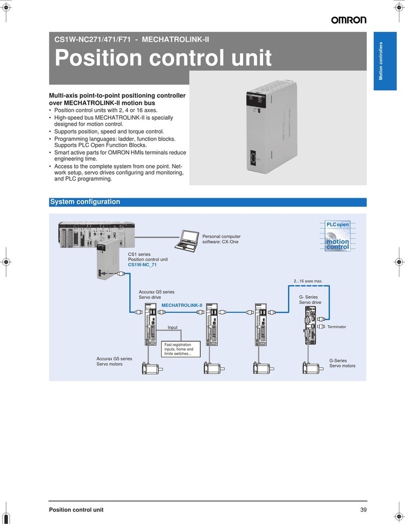
Omron
Omron CS1W-NC271 System configuration
Honeywell
Honeywell D15P installation instructions
SVF
SVF VB41 Series Installation operation & maintenance
Panasonic
Panasonic SF-AC instruction manual
Victaulic
Victaulic 867-7UF Installation, operation and maintenance manual

Crux
Crux Sightline ACPMB-50W manual
Enerwave
Enerwave ZWN-333M installation instructions
NXP Semiconductors
NXP Semiconductors Freescale MC9S12C32 user guide
GEM
GEM 651 Installation, operating and maintenance instructions

