Rauch E-CLICK User manual

E-CLICK AXIS-M
MDS
INSTRUCTION MANUAL
Please read carefully
before using the ma-
chine.
Keep for future reference.
This instruction manual/assembly in-
struction is to be considered as part of
the machine. Suppliers of new and se-
cond-hand machines are required to
document in writing that the instructi-
on manual/assembly instruction was
delivered with the machine and han-
ded over to the customer. Original instructions
5901360-c-en-0519

Foreword
Dear customer,
By purchasing the control unit E-CLICK for the mineral fertiliser spreaders AXIS and MDS, you
have shown confidence in our product. Thank you! We want to justify your trust. You have purcha-
sed a powerful and reliable control unit. Our customer service is always at your disposal, should
any problems arise.
Please read this operating manual and the operating manual of the mineral fertiliser sprea-
der carefully before commissioning the mineral fertiliser spreader and follow the advice gi-
ven.
This manual could also describe equipment and options that are not included in your control unit.
You should be aware that damage caused by incorrect operation or improper use may not be
covered by warranty claims.
Technical improvements
We are continuously improving our products. Therefore, we reserve the right to make any
improvements and changes to our machine that we consider necessary without notice.
This constitutes no obligation to make such improvements or changes on machines that
have already been sold.
We will be pleased to answer any other questions that you might have.
Yours sincerely
RAUCH
Landmaschinenfabrik GmbH

Table of Contents
I
Foreword
Technical improvements
1 User instructions 1
1.1 About this operating manual . . . . . . . . . . . . . . . . . . . . . . . . . . . . . . . . . . . . . . . . . . . 1
1.2 Notes on the depiction of information in this manual . . . . . . . . . . . . . . . . . . . . . . . . . 1
1.2.1 Significance of warnings . . . . . . . . . . . . . . . . . . . . . . . . . . . . . . . . . . . . . . . . 1
1.2.2 Instructions and procedures. . . . . . . . . . . . . . . . . . . . . . . . . . . . . . . . . . . . . . 2
1.2.3 Listings. . . . . . . . . . . . . . . . . . . . . . . . . . . . . . . . . . . . . . . . . . . . . . . . . . . . . . 3
1.2.4 References. . . . . . . . . . . . . . . . . . . . . . . . . . . . . . . . . . . . . . . . . . . . . . . . . . . 3
2 Layout and function 5
2.1 Overview of supported mineral fertiliser spreader versions. . . . . . . . . . . . . . . . . . . . 5
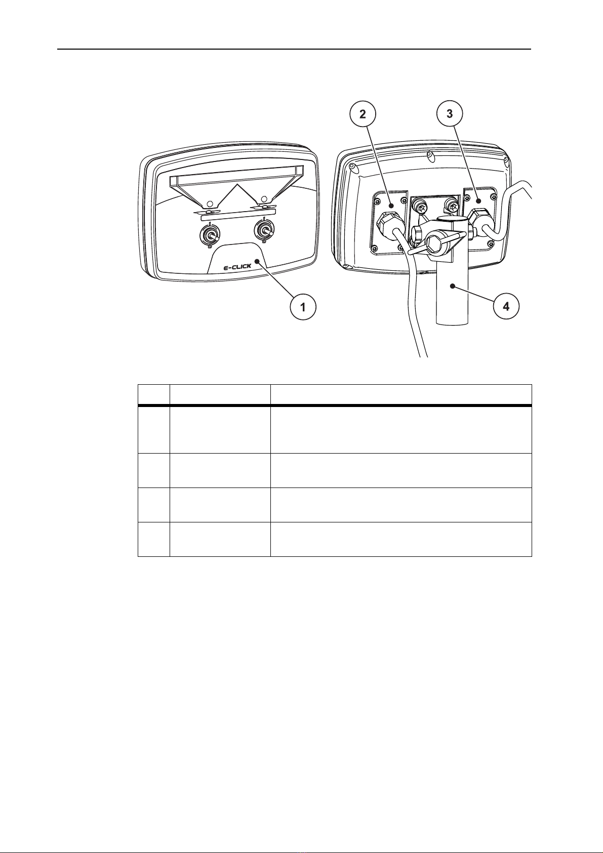
2.2 Layout of control unit - overview . . . . . . . . . . . . . . . . . . . . . . . . . . . . . . . . . . . . . . . . 6
2.3 Operating elements . . . . . . . . . . . . . . . . . . . . . . . . . . . . . . . . . . . . . . . . . . . . . . . . . . 7
2.4 Display . . . . . . . . . . . . . . . . . . . . . . . . . . . . . . . . . . . . . . . . . . . . . . . . . . . . . . . . . . . . 8
2.5 Nameplate . . . . . . . . . . . . . . . . . . . . . . . . . . . . . . . . . . . . . . . . . . . . . . . . . . . . . . . . . 9
3 Attachment and installation 11
3.1 Tractor requirements . . . . . . . . . . . . . . . . . . . . . . . . . . . . . . . . . . . . . . . . . . . . . . . . 11
3.2 Connections, sockets. . . . . . . . . . . . . . . . . . . . . . . . . . . . . . . . . . . . . . . . . . . . . . . . 11
3.3 Attaching the control unit . . . . . . . . . . . . . . . . . . . . . . . . . . . . . . . . . . . . . . . . . . . . . 12
3.4 Connecting the control unit . . . . . . . . . . . . . . . . . . . . . . . . . . . . . . . . . . . . . . . . . . . 13
4 Operation E-CLICK 15
4.1 Prepare the control unit . . . . . . . . . . . . . . . . . . . . . . . . . . . . . . . . . . . . . . . . . . . . . . 15
4.2 Switching positions of the toggle switches. . . . . . . . . . . . . . . . . . . . . . . . . . . . . . . . 16
4.3 Adjusting the application rate. . . . . . . . . . . . . . . . . . . . . . . . . . . . . . . . . . . . . . . . . . 17
4.4 Reference run . . . . . . . . . . . . . . . . . . . . . . . . . . . . . . . . . . . . . . . . . . . . . . . . . . . . . 18
4.5 Spreading using E-CLICK . . . . . . . . . . . . . . . . . . . . . . . . . . . . . . . . . . . . . . . . . . . . 19
4.6 Error indication. . . . . . . . . . . . . . . . . . . . . . . . . . . . . . . . . . . . . . . . . . . . . . . . . . . . . 20
4.6.1 Short circuit . . . . . . . . . . . . . . . . . . . . . . . . . . . . . . . . . . . . . . . . . . . . . . . . . 20
4.6.2 Not connected . . . . . . . . . . . . . . . . . . . . . . . . . . . . . . . . . . . . . . . . . . . . . . . 20
4.6.3 Close the metering slides. . . . . . . . . . . . . . . . . . . . . . . . . . . . . . . . . . . . . . . 21
Terms/conditions of warranty

Table of Contents
II

User instructions
3
1
1 User instructions
1.1 About this operating manual
This operating manual is an integral part of the control unit E-CLICK.
The manual contains important instructions for a safe, appropriate and
economic use as well as maintenance of the control unit. Compliance with its
stipulations helps to avoid risks, reduce maintenance costs and downtime and
to increase the machine's reliability and service life.
The operating manual is part of the machine. The complete documentation must
be kept in an easily accessible location close to where the control unit is used
(e. g. on the tractor).
The operating manual does not replace your own responsibility as the operator
and operating personnel of the control unit E-CLICK.
1.2 Notes on the depiction of information in this manual
1.2.1 Significance of warnings
The warning instructions in this manual have been structured according to the
degree of danger and the probability of their occurrence.
Danger signs and symbols inform the user about other construction-related and
unavoidable residual risks that may be encountered when operating the machine.
The warning notes used are structured as follows:
Example
Signal word
Symbol Explanation
n DANGER
Risk to life if warning is not observed
Description of the danger and possible consequences.
Ignoring these warnings will result in very serious or even fatal
injury.
Measures to prevent the danger.

User instructions1
4
Warning severity level
The degree of danger is indicated by the signal word. The levels are classified as
follows:
n DANGER
Type and source of danger
This warning warns of a danger posing an immediate threat to the
health and life of persons.
Ignoring these warnings will result in very serious or even fatal
injury.
Always observe the measures described to prevent this
danger.
n WARNING
Type and source of danger
This warning warns of a possible dangerous situation for the
health of persons.
Ignoring these warnings will result in very serious injury.
Always observe the measures described to prevent this
danger.
n CAUTION
Type and source of danger
This warning warns of a potentially dangerous situation for
personal health or of material and environmental damage.
Ignoring this warning can result in injuries and damage to the
product or the general area.
Always observe the measures described to prevent this
danger.
NOTICE
General information containing application tips and particularly useful
information, but which constitutes neither warnings nor hazards.

User instructions
5
1
1.2.2 Instructions and procedures
Steps that the operator must carry out are shown as a numbered list.
1. Instruction for action step 1
2. Instruction for action step 2
Instructions involving only one step are not numbered. The same applies for
action steps that do not have a specific sequence.
A bullet is placed in front of these instructions:
Handling instruction
1.2.3 Listings
Listings without a specific sequence are shown with bullet points (level 1) and
dashes (level 2):
Property A
- PointA
- PointB
Property B
1.2.4 References
References to other text passages in the document are indicated with section
number, headline text and page number:
Example: See also Chapter 3: Attachment and installation, page 11.
References to other documents are indicated as note or instruction without exact
chapter or page number:
Example: Please also observe the instructions contained in the manual for
the universal drive shaft.

User instructions1
6

Layout and function
5
2
2 Layout and function
2.1 Overview of supported mineral fertiliser spreader versions
AXIS C MDS
AXIS 20.1/20.2 C
AXIS 30.1/30.2 C
AXIS 40.1/40.2 C
AXIS 50.1/50.2 C
MDS 10.1 C
MDS 11.1 C
MDS 12.1 C
MDS 17.1 C
MDS 19.1 C

Layout and function2
6
2.2 Layout of control unit - overview
Figure 2.1: E-CLICK control unit
No. Description Function
1 Control panel Consists of toggle switches for controlling the unit
and multicolour LEDs for displaying machine
conditions.
2 Machine cable plug
connector
4-pin plug connector for connecting the machine
cable to the actuators.
3 Power supply 3-pin plug connector for connecting the power supply
according to DIN 9680 / ISO 12369.
4 Unit mounting
bracket
Fastens the control unit to the tractor.

Layout and function
7
2
2.3 Operating elements
Use the two toggle switches on the E-CLICK control unit to open and close the
metering slides while spreading.
Figure 2.2: Arrangement of toggle switches
[1] Toggle switch left: Controls the left metering slide
[2] Toggle switch right: Controls the right metering slide
2
1

Layout and function2
8
2.4 Display
Multicolour LEDs on the display area of the E-CLICK show the condition of the
metering slides. Changes in colour show whether the metering slides are open,
closed or in motion.
Figure 2.3: E-CLICK multicolour LEDs
[1] LED condition actuator left
[2] LED condition actuator right
LED Condition
LED green The metering slides are fully open
LED orange The metering slides are in motion
LED red The metering slides are fully closed
LED red flashing Error message, no metering slide movement
LED off The condition of the metering slides for the E-CLICK are
currently unknown
2
1

Layout and function
9
2
2.5 Nameplate
A nameplate is attached to the back of the E-CLICK control unit where you can
find important information about your unit.
NOTICE
Always have this information ready when contacting your RAUCH point of
contact!
E-CLICK technical data
Nominal voltage 12 V / DC
Voltage range 11.0 V to 16.5 V / DC
Nominal current 8.0 A
Operating temperature range −20 °C to +60 °C
Protection class according to
ISO 20653
IP54

Layout and function2
10

Attachment and installation
11
3
3 Attachment and installation
3.1 Tractor requirements
Before attaching the control unit, check that your tractor meets the following
requirements:
A minimum voltage 11 V must be guaranteed at all times, even when several
consumers are connected at the same time (e. g. air conditioning, lights).
3.2 Connections, sockets
Power supply
The control unit is supplied with power from the tractor using the 3-pin power
supply socket (DIN 9680/ISO 12369).
[1] PIN 1: not required
[2] PIN 2: (15/30): +12 V
[3] PIN 3: (31): Ground
Figure 3.1: Power socket pin layout

Attachment and installation3
12
3.3 Attaching the control unit
Perform the task steps in the following order.
1. Install the holder as shown in Step 1.
2. Tightly screw the installed holder onto the E-CLICK control unit with the four
fixing screws and washers (Step 2).
Figure 3.2: Installing the unit holder
3. Select a suitable location in the tractor cab (in the driver's field of vision)
where you wish to attach the E-CLICK control unit.
4. Attach the control unit with the holder at the selected location.
1
2

Attachment and installation
13
3
3.4 Connecting the control unit
Perform the task steps in the following order.
1. Connect the 4-pin machine cable with its counterpart on the E-CLICK control
unit.
2. Connect the E-CLICK control unit power supply with the power socket.
The E-CLICK control unit is ready to operate.
Schematic connection overview:
Figure 3.3: E-CLICK schematic connection overview
[1] Tractor
[2] Power socket
[3] 3-pin plug connector according to DIN 9680 / ISO 12369
[4] Actuator metering slide right
[5] Actuator metering slide left
[6] Plug connector machine cable for actuator left
[7] Plug connector machine cable for actuator right
[8] Machine cable
[9] 4-pin machine connector
[10] 4-pin machine connector
[11] E-CLICK control unit
L
1
2
3
4
5
6
7
8
9
10
11
R

Attachment and installation3
14

Operation E-CLICK
17
4
4 Operation E-CLICK
4.1 Prepare the control unit
Requirements:
The control unit is connected properly to the mineral fertiliser spreader and
the tractor (see chapter 3.3: Connecting the control unit, page 14).
A minimum voltage of 11 V is guaranteed.
NOTICE
The control unit E-CLICK is ready to operate once it is connected to the on-
board power supply of your tractor. Separate activation is not required!
n CAUTION
Risk of injury caused by ejected fertiliser
In the event of faults, the metering slide could open unexpectedly
en route to the spreading location. There is a danger of people
slipping on the discharged fertiliser and injuring themselves.
Before driving to the spreading location, the control unit
E-CLICK must be disconnected from the on-board power
supply!

Operation E-CLICK4
18
4.2 Switching positions of the toggle switches
Opening and closing the metering slides while spreading is controlled by means
of 2 toggle switches on the control E-CLICK unit.
In order that the actuator motors are not overloaded, the actuators are switched
off automatically when moving against a blockade.
Figure 4.1: Toggle switch position and switching state
[1] OPEN (I)
[2] Neutral
[3] CLOSE (0)
Switching state OPEN, the metering slide opens.
Switching state Neutral, actuator control is switched off.
Switching state CLOSE, the metering slide closes.
NOTICE
Requirements for spreading with the control unit E-CLICK: The slider openings
on the mineral fertiliser spreader are set properly!
NOTICE
The toggle switches have 3 locking switching positions. The required
switching state is set by operating the toggle switches.
NOTICE
Switching the toggle switch to the Neutral position stops the respective
metering slide being opened or closed at any time!
Table of contents
Other Rauch Control Unit manuals

Rauch
Rauch AXIS ISOBUS User manual

Rauch
Rauch Axent Isobus User manual

Rauch
Rauch QUANTRON-A AXIS-M 20 Q User manual

Rauch
Rauch AERO GT ISOBUS User manual

Rauch
Rauch QUANTRON-A User manual

Rauch
Rauch QUANTRON-A User manual

Rauch
Rauch QUANTRON-A User manual

Rauch
Rauch QUANTRON User manual

Rauch
Rauch AXMAT DUO User manual

Rauch
Rauch EcoTron User manual
Popular Control Unit manuals by other brands

Miele
Miele XKM 3200 WL LMD operating instructions

CALEFFI
CALEFFI 630 Series manual

White Rodgers
White Rodgers 36C03 installation instructions

Dixon
Dixon BAYCO 4040RD Installation & operating instructions

Rockwell Automation
Rockwell Automation 1797-IE8 installation instructions

EVVA
EVVA Xesar E.X.WL.CU0 Assembly manual