Solo 530 User manual

9 530 110 10/2007
530
Gebrauchsanweisung
Instruction manual
Instructions d'emploi
Manual de instrucciones
Istruzioni per l'uso
Achtung!
Lesen Sie vor der ersten Inbetriebnahme diese
Gebrauchsanweisung gründlich durch und
beachten Sie unbedingt die
Sicherheitsvorschriften!
Important!
Read this instruction manual carefully before first
operation and strictly observe the safety
regulations!
Attention!
Lire attentivement ce manuel avant la première
mise en service et observer absolument les
prescriptions de sécurité!
¡Atención!
Es indispensable leer con mucha atención las
instrucciones de manejo antes de utilizarla por
primera vez. ¡Preste especial atención a las
recomendaciones de seguridad!
Attenzione!
Prima della prima messa in funzione leggere a
fondo le presenti istruzioni per l'uso e osservare
assolutamente le norme di sicurezza.
Balkenm!her
Motormower
Motofaucheuse
Motosegadora
Motofalciatrice

2
ERLÄUTERUNG DER MASCHINENTEILE:
1- Radantriebshebel
2- Handgashebel
3- Messerantriebshebel
4- Führungsholm
5- Horizontaler Reversierstarter
6- Grasverteiler
7- Zentralmähwerk
8- Tankeinfüllstutzen
9- Primerpumpe
10- Ballengriff zur Holmbefestigung
11- Öleinfüllstutzen
-Abbildung Nr.1-
SPEZIFIKATIONEN UND TECHNISCHE DATEN
Modell: SOLO 530
Gewicht: 49 Kg.
Motor: 4 Takt Benzin
Marca: BRIGGS & STRATTON SPRINT 40
Model: 10D902
Hubraum: 158 cc.
Leistung PS: 4 (Kw 2,94) bei 3.200U/Min
•Kraftstoff: bleifreies Benzin
-Abb. Nr.2-
•Horizontaler Reversierstarter
•Unfallverhütungsvorrichtung am Holm zum Anhalten von Balken und
Rädern
•Luftfilter
•Benzinverbrauch bei 3200 U/Min :0,8 Kg/h
•Motorenöl: Reinigendes Öl SAE 30
•Ölinhalt des Motors: 0,6 Lt.
•Antrieb : Eingangbetrieb mit ölbadgeschmierter Mehrscheibenkupplung
•ANTRIEBSSCHMIERUNG MIT ÖL: SHELL TELLUS T22
•Vorschubgeschwindigkeit: 2,15 km/h
•Räder und Mähbalkenauskupplung per Handkupplungshebel
•Führungsholm mit Vibrationsschutz
•Räder 330 X 95 Typ "Traktor" 3.50.6
•Zentralmähwerk Balken 71 cm breit
•Riemenantrieb über Kupplungsriemenscheibe
Zur Identifikation der Maschine (Seriennummer, Motor, Gewicht etc.), beachten
Sie bitte das Typenschild (Position gemäß Abbildung 2, Buchstabe A).

3
-Abbildung Nr.3
VERPACKUNG UND TRANSPORT
BREITE:100cm. TIEFE:47cm. HÖHE:63cm.
-Abb.Nr.4-
!Nehmen Sie den Balkenmäher aus der Verpackung.
!Mit den beiden Schrauben und den beiden Ballengriffen, die am
Holm angebracht sind, befestigen Sie die Holme am Lenkerträger.
Dabei ist auf den korrekten Verlauf der Antriebskabel zu achten.
(Abb.1 - Pos.10)
!Befestigen Sie den Balken an der Maschine. Hierzu die Hakenfeder
(Abb.4 Pos.A) am Zapfen (Pos.B) herausziehen, den Zapfen in das
Gestell (Pos.C) stecken und die Feder (Pos.A) wieder in Richtung
der Bohrung einsetzen. Den Plastikmitnehmer nehmen (Abb.4
Pos.D) und ihn in den Grastrenner (Pos.E) stecken. Das Ganze in
den Zapfen von der Schwinge (Pos.F) stecken, wo sich das Loch auf
Mitnehmer und Halter befindet. Den Halter (Pos.E) am Balken
befestigen, indem die beiden Schrauben (Pos,G) in die
Gewindebohrungen am Balken selbst gesteckt werden.
!Für den Transport der Maschine den Benzintank entleeren und die Kunststoffabdeckung auf die Schnittfläche des
Mähbalkens aufsetzen.
WICHTIG: BEI DER VERPACKTEN MASCHINE BEFINDET SICH WEDER ÖL NOCH BENZIN IM MOTOR.
SICHERHEITSVORSCHRIFTEN
•Lesen Sie die Gebrauchsanweisung genau durch.
•Jugendliche unter 16 Jahren dürfen die Maschine nicht benutzen.
•Der Benutzer ist im Arbeitsbereich der Maschine gegenüber Dritten verantwortlich.
•Unerfahrene Personen dürfen die Maschine nicht verwenden, bevor Sie die Gebrauchsanweisung genau gelesen und
verstanden haben.
•Für den Transport muss der Führungsholm abmontiert und der Tank vorher geleert werden.
•Bevor man von der Maschine weggeht oder Regelungen an den Zusatzgeräten vornimmt, muss der Motor zum
Stillstand gebracht werden.
•Eventuell verschüttetes oder übergelaufenes Benzin entfernen.
•Füllen Sie nie bei laufendem oder zu heißem Motor Kraftstoff nach. Nur im Freien auftanken und dabei nicht rauchen.
Nicht in der Nähe eines offenen Feuers auftanken!

4
•Beim Mähen an Böschungen und Hängen ist besondere Vorsicht geboten (z.B. beim Mähen entlang der Schräglinie,
ist das Tragen von Schuhen mit rutschfester Sohle notwendig.)
•Vor einem eventuellen Messerwechseln stets Handschuhe anlegen
•Sollte der Mäher durch Auffahren auf ein Hindernis einen Stoß erlitten haben, ist eine fachgemäße Überprüfung
erforderlich.
•Halten Sie Hände und Füße vom laufenden Schneidwerkzeug fern.
•Motor nicht in einem geschlossenen Raum laufen lassen, wo sich die Abgase, die Kohlenmonoxid enthalten,
ansammeln können.
•Benutzen Sie immer komplettes Zubehör, das mit der Sicherheitsvorrichtung versehen ist.
•Für die Reinigung, den Zusammenbau, die Demontage muss der Motor immer abgestellt werden.
•WICHTIG: Mähen Sie nicht an Hängen mit mehr als 30% Neigung.
•Für Unfälle die aus der Nichtbeachtung dieser Gebrauchsanweisung entstehen, können wir nicht haftbar gemacht
werden.
STARTEN UND ABSTELLEN DES BALKENMÄHERS
-Abb. Nr.5-
Vor jedem Starten ist folgendes zu kontrollieren:
•Ob das Gerät aufgetankt ist
•Ölstand: Das Motorenöl bis zum Niveau des Ölmessstabes einfüllen und regelmäßig
kontrollieren.
•Dass alle Sicherheitsfunktionen richtig arbeiten.
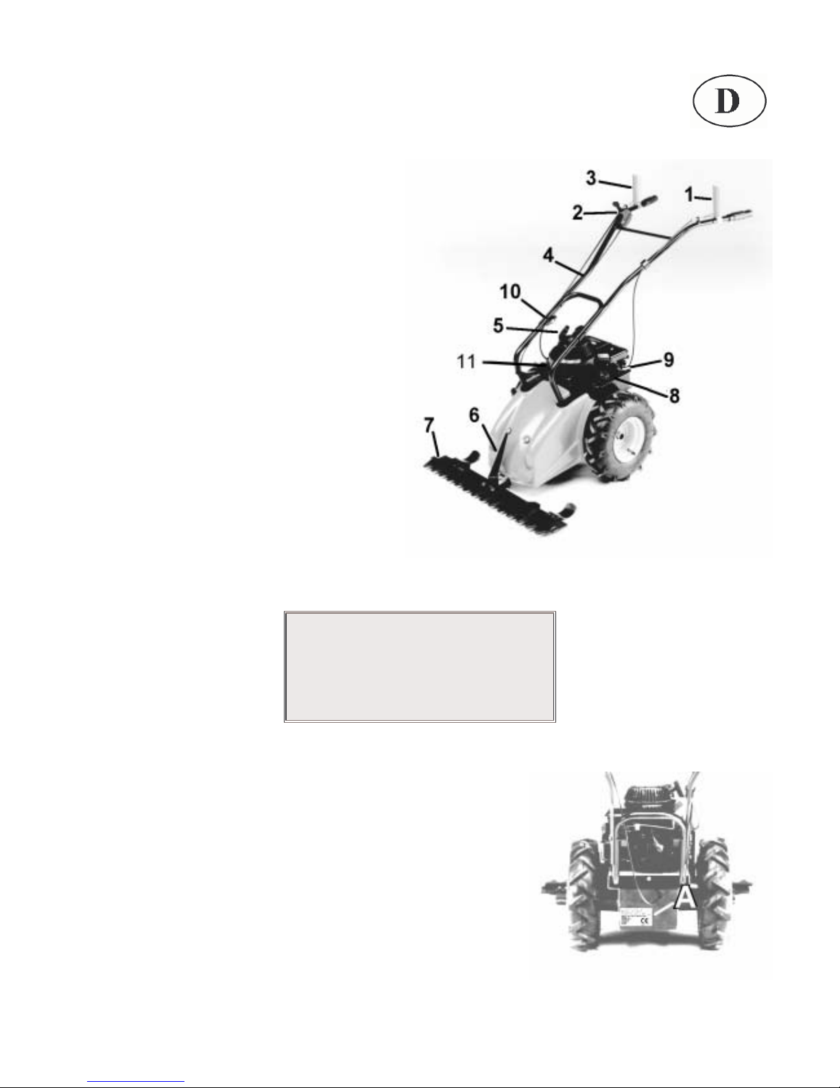
•Bei kaltem Motor drücken Sie dreimal die Primerpumpe (Abbildung 1, Nr. 9), bevor
Sie den Motor starten (siehe auch Motoren-Gebrauchsanweisung).
•Starten Sie die Maschine immer im Freien, in seitlicher Stellung.
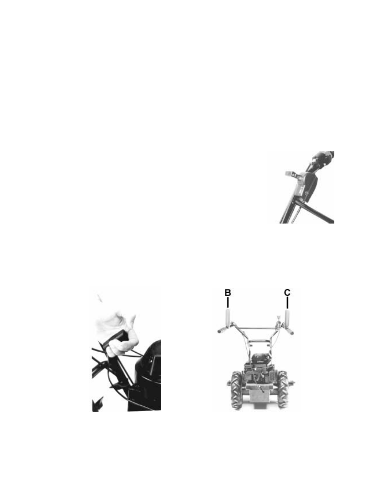
•Der Handgashebel muss auf "START" gestellt sein. Dann fassen Sie den
Starterhandgriff mit einer Hand (Abbildung 5), ziehen leicht bis ein Widerstand zu
spüren ist, dann kräftig ziehen. Nachdem der Motor läuft, lassen Sie das Starterseil
nicht einfach zurückschnellen, sondern führen Sie es von Hand ins Gehäuse zurück,
bis es ganz aufgerollt ist.
•Für ein richtiges Starten des Motors lesen Sie den Abschnitt "Starten" im Gebrauchs- und Wartungshandbuch Motor
durch.
•Wenn der Motor läuft, muss der Handgashebel auf mittlere Position zurückgestellt werden (Abbildung 5)
•Zum Vorschub der Maschine den Kupplungshebel drücken (Abb.7, Pos.B), beim Loslassen des Hebels hält die
Maschine an.
•Der Balkenmäher kann bei gelöstem Kupplungshebel frei vor - oder zurückgeschoben werden. (Leerlauf)
SICHERHEITSHEBEL
Die Hauptfunktion dieses Hebels besteht darin, den Motor auszuschalten, wenn die Griffe von dem Führungsholm
weggenommen werden. Vor dem Arbeitsbeginn sicherstellen, dass das Ein- und Ausrücken des Antriebs an Rädern und
Balken mit den Hebeln an den Holmen korrekt erfolgt.
-Abb. Nr.6- -Abb. Nr.7-

5
GEBRAUCH UND EINSTELLUNGEN
Vor Beginn der Mäharbeiten das Mähmesser ölen und dann den Motor unter Befolgung der Anweisungen anlassen.
•Das Einrücken der Kupplung mit dem Kupplungshebel zur Übertragung des Antriebs auf die Räder und auf den
Mähbalken muss stets im mittleren Drehzahlbereich erfolgen. Hierbei den Hebel langsam loslassen.
•Beim Mähbeginn den Gashebel auf 3/4-Position oder "MAX" stellen, um eine ausreichende Leistungsversorgung zu
gewährleisten.
•Wenn der Balkenmäher an einer Mauer oder am Rand eines Gehsteigs verwendet wird, auf einen ausreichenden
Sicherheitsabstand achten, um ein Anstoßen des Messers zu verhindern, wodurch der Mähbalken beschädigt werden
könnte.
•Wenn der Riemen abrutscht, den Regler am Kupplungshebel lockern und einen Vorlauf von ca. 5 mm vor dem
Einrücken der Kupplung einstellen.
•Zur Höhenverstellung der Sterze an den Ballengriffen drehen, mit denen die Sterze am Lenkerträger befestigt sind; 2
Höhenpositionen sind möglich (Abbildung 1, Pos.10).
•Zur Einstellung des Motors im Motorhandbuch unter "Einstellungen" nachlesen.
-Abb. Nr.8- -Abb. Nr.9-
WARTUNG
•Für den Ölwechsel und alle weiteren Wartungsarbeiten am Motor (Zündkerzen, Luftfilter, Einstellungen) siehe
mitgeliefertes Motorhandbuch.
•Hinweis: Um den Ölablassdeckel am Motor abschrauben zu können, den rückwärtigen Deckel abnehmen (Abbildung
8, D).
•Regelmäßig den Ölstand im Antriebsgehäuse über dem Deckel überprüfen und bei Bedarf nachfüllen.
•Das Öl vollständig auslaufen lassen. Den Deckel wieder fest aufsetzen und mit frischem Öl des empfohlenen Öltyps
bis zum korrekten Ölstand auffüllen.
•Sollte der Grasschnitt trotz der Einstellungen nicht einwandfrei ausfallen, muss das Messer geschärft, nachgestellt
oder ausgewechselt werden.
•Für alle mechanischen Wartungsarbeiten, insbesondere während des Garantiezeitraums, empfiehlt es sich, die
Fachwerkstätten unserer Vertragshändler aufzusuchen.
•Zur Erleichterung der Transports können die Holme über die beiden Ballengriffe (Abbildung 1, 10) abmontiert
werden. Dieselbe Empfehlung gilt für den Mähbalken. Zur Abnahme des Mähbalkens den Spezialsplint am
Balkenträger (Abbildung 9, Pos.E) herausziehen. Hierbei stets Arbeitshandschuhe tragen und die Abdeckung auf die
Schnittfläche aufsetzen.
•Regelmäßig den Anzug der Schrauben überprüfen; hierbei insbesondere die Feststellschrauben des Balkens an
seinen Träger.
•Periodisch den Zahnkranz für die Antriebsübertragung an die Räder fetten (Abb. 9, Pos. “F”).
•Das verbrauchte Öl ist umweltgerecht zu entsorgen.
ACHTUNG
Es wird empfohlen, den Motor nicht laufen zu lassen, wenn die Maschine
nicht für die Arbeit verwendet wird

6
SICHERHEITSPRÜFUNGEN UND ZERTIFIZIERUNG
CE-KONFORMITÄTSERKLÄRUNG entsprechend der Richtlinie 98/37 CE und der Richtlinie EMC 89/336/CE
Kleinmotoren GmbH, Stuttgarter Straße 41, D-71069 Sindelfingen
erklärt in alleiniger Verantwortung, dass die Maschine, auf die sich diese Erklärung bezieht, den einschlägigen
grundlegenden Sicherheits- und Gesundheitsanforderungen der Richtlinie 98/37/CE entspricht.
TYP BALKENMÄHER MODELL SOLO 530
Zur sachgerechten Umsetzung den EG-Richtlinien genannten Sicherheits- und Gesundheitsanforderungen wurden
folgende Normen und technische Spezifikationen herangezogen: UNI EN ISO 12100-1 und UNI EN ISO 12100-2; UNI
EN 12733 für handgeführte Balkenmäher mit rotierenden Schneidmessern oder mit Hin- und Herbewegung, die in der
Land- und Forstwirtschaft sowie im Gartenbau verwendet werden.
SOLO Kleinmotoren GmbH
SINDELFINGEN, den 18/10/2007
Wolfgang Emmerich
Geschäftsführer
PRÜFUNGSERGEBNIS
Typ BALKENMÄHER MODELL
SOLO 530
Schalleistungspegel LwA = von LdB (A) 92 bis 104 LdB (A).
Schalldruck am Ohr des Anwenders: LpA = von 81 dB (A) bis 91,5 dB (A)
Prüfbedingung: Höhe 1,6 m Holmmitte
Vibration am Holm mit Wiegung UNI EN 1033-1 von 8,4 m/s2bis 18,17 m/s2.
Diese Konformitätserklärung verliert ihre Gültigkeit, wenn das Produkt ohne Zustimmung umgebaut oder verändert wird.

7
LIST OF MACHINE PARTS
1. Wheel engage-release lever
2. Accelerator hand lever
3. Lever for blade motion
4. Handles
5. Motor ignition
6. Grass divider
7. Central cutting blade
8. Fuel inlet
9. “Primer” push-button
10. Handlebar regulator
11. Motor oil cap
-Fig. n°1-
IDENTIFICATION AND TECHNICAL CHARACTERISTICS
Model: SOLO 530
Weight: 49 Kg.
Motor: 4 stroke
Make: BRIGGS & STRATTON SPRINT 40
Model: 10D902
Swept volume: 158 cc.
Max. power to driving shaft:
HP: 4 (Kw 2,94) at 3.200 rpm/1’
•Motor fuel: unleaded petrol
-Fig. n°2-
•Complete with self-winding start-up device
•Safety device on handles to stop machine
•Dry air filter
•Consumption at 3600 r.p.m.: 0.8 Kg/hour
•Motor oil: AGIP DIESEL SIGMA SAE 30
•Oil quantity in gearbox : 0.6 lt
•Gearbox: oil bath single gear
•Gearbox oil: SHELL TELLUS T22
•Mowing speed : 2,15 Km/h
•Manually controlled wheel release and cutting bar
•Steering handles mounted on vibration-damping supports
•"Tractor" type rubber wheels 330 x 95 (3.50-6)
•Central mowing unit with bar cm.71
•Clutch with belt tightening pulley.
For machine identification (serial number, motor, weight, power) refer to the
data plate as shown in the photo. See Ref. "A in Fig. 2.

8
-Fig. n°3-
PACKING AND TRANSPORT
"WIDTH: 100 cm. "DEPTH:47cm. "HEIGHT:63cm.
-Fig.n.4-
•Remove the power mower from its packing.
•Fix the handles to the handlebar support using the two screws and two
knobs pre-mounted on the handle. Make sure to position the control
cables correctly.
•Fix the bar to the machine, removing the hooked spring (Fig.4 Ref.A)
located on the pin of the bar support (Ref.B). Insert the pin of the bar
support into the frame (Ref.C) and reinsert the spring (Ref.A) in the
direction of the hole. Take the plastic cylinder (Fig.4 ref.D), insert it into
the grass divider (Ref. E) and insert all into the pin of the bar (Ref.F)
correspondingly to the hole on the grass divider and on the cylinder. Fix
the grass divider (Ref. E) to the bar, inserting two screws (Ref.G) into the
threaded holes on the bar corresponding to the grass divider.
•If the machine is to be transported, empty out the petrol tank and always
apply the plastic protective strip to the E.S.M. cutting bar blade. Read
the E.S.M. sheet attached.
IMPORTANT: THE PACKED MACHINE IS SUPPLIED WITH THE MOTOR WITHOUT OIL OR PETROL.
SAFETY RULES
•Read carefully the operation and maintenance manual enclosed with the machine.
•The use of the machine is prohibited to persons under 16 years of age.
•The operator is liable for damages since the machine is under his control.
•Those unfamiliar with the machine or who have never used it are obliged to read the operation and maintenance
manual before operation.
•In case of transport, disassemble the bar and empty the petrol out of the tank.
•If the machine is left unattended, ensure that it cannot start up again.
•Before running the machine, the operator must havea5meterradiusoffreespacearound him.
•Dry any petrol leaks.

9
•Fill up the tank with the motor off. Filling the tank or transferring fuel must always be performed outdoors, away from
flames or heat sources. Do not smoke during this operation.
•When mowing in mountainous areas or on slopes, mow horizontally and use non-skid equipment on shoes and
wheels.
•If the blade needs replacement, observe E.S.M. operation and maintenance procedures.
•If the bar suffers impact, check the condition of the bar before resuming work.
•Keep feet and hands far away from the cutting bar and all rotating parts.
•Do not run the motor where exhaust containing carbon monoxide may accumulate.
•Never use the mower incomplete or without its safety device.
•Do not assemble/disassemble or clean the cutting bar or other equipment with the motor running.
•Caution! When the clutch is engaged the cutting bar is always in motion.
•Caution! Do not mow areas with slopes exceeding 30%.
•We will not be held liable for accidents caused by the failure to observe these rules.
STARTING AND STOPPING THE POWER MOWER
-Fig. n°5-
Every time you get ready to start the motor, make a careful check of the following:
•Make sure that fuel is in the tank.
•Check the motor oil level: CAUTION: MACHINES OUT OF THE FACTORY DO NOT
CONTAIN OIL IN THE MOTOR. Make sure to add oil up to the level on the dipstick.
•CONSULT THE OPERATION AND MAINTENANCE MANUAL OF THE MOTOR UNDER
"BEFORE START-UP"
•Check that all safety systems are released and functioning.
•Start the machine always in the open air and stay at its side.
•Bring the accelerator hand lever (Fig. 5) to the "MAX" position, grasp the cord handle
(Fig. 6) and pull it slightly until you feel some resistance, then pull harder. Make sure that
the cord does not return by itself -- accompany it with your hand.
•With the motor running, bring the accelerator lever (Fig. 5) to the middle position To
make the machine go forward squeeze the clutch lever (Fig. 7 Ref. B) ; if you leave the
lever, the machine stops.
•To move the mower freely forward or back, squeeze the wheel release lever (neutral position) after squeezing the
clutch lever.
SAFETY DEVICE FOR STOPPING THE MOTOR
The main function of the lever Fig. 7 is to turn off the motor when releasing your hands from the steering handles.
Every time you get ready to start the motor, check if the engaging and disengaging of the transmission to the wheels and
to the bar through the levers on the handlebars work regularly.
-Fig. n°6- -Fig. n°7-

10
OPERATING AND REGULATING THE MACHINE
Before you start mowing, oil the cutting blade, then start the motor as follows:
•
Engaging the transmission to the wheels and the cutting bar by means of the clutch lever must be carried out with
the motor at a middle r.p.m. and by slowly releasing the lever.
•
When starting to mow, position the accelerator lever at 3/4 or at "MAX" to ensure adequate power.
•
When mowing along a wall or the edge of a sidewalk, be careful to keep a safety distance so that the blade does not
suffer impact. If not, the cutting bar may undergo damage.
•
If the belt slips, loosen the register located on the clutch lever and leave a travel of approximately 5 mm before the
clutch engagement.
•
Adjusting the height of the handles is carried out by moving the knobs securing them on the handlebar support. This
will allow two positions (Fig. 1 Ref. 10).
•
To regulate the motor, read the manual on the motor under "REGULATIONS".
-Fig. n°8- -Fig. n°9-
MAINTENANCE
•
For changing the oil and other maintenance operations on the motor (spark plugs, air filter, regulations), refer to the
motor manual provided.
•
NB: To unscrew the oil drain plug of the motor, disassemble the rear cover (Fig. 8 Ref. D).
•
Empty the gearbox of oil by unscrewing the oil drain plug, let the oil drain completely. After screwing back the cap
tightly, fill to the correct level with new oil recommended by the manufacturer.
•
Do not leave the exhausted oil in the environment.
•
Check periodically the oil level and fill in with new oil if necessary.
•
If the grass is not cut in a satisfactory manner despite the adjustments, the blade must be sharpened or replaced.
Follow the instructions on the E.S.M. maintenance sheet.
•
For any mechanical repair, especially during the warranty period, we recommend to go to a specialized repair shop
of the dealer.
•
For transporting convenience, the handles can be disassembled by means of the two knobs (Fig. 1 Ref. 10). The
same is recommended for the cutting bar, which is easily disassembled by removing the special split pin on the bar
support (Fig. 9 Ref. E). Always use gloves and apply the protective strip to the blade.
•
Regularly check that screws are tight. Pay special attention to the screws fastening the bar to its support.
•
Lubricate periodically the crown wheel for the wheel transmission (Fig. 9 Ref. “F”).
CAUTION:!!
It is advised not to keep the motor running when the machine is not
being used for its specific purpose

11
SAFETY TESTS AND CERTIFICATION
Declaration of CE conformity in accordance with the directive 98/37 CE and the directive EMC 89/336/CE
Kleinmotoren GmbH, Stuttgarter Straße 41, D-71069 Sindelfingen
We declare that the machine complies with the essential requirements for health and safety in accordance with Directive
98/37/CE.
POWER MOWER TYPE MODEL SOLO 530
For verification of the conformity with the above-mentioned Directives reference has been made to following
specifications: UNI EN ISO 12100-1 and UNI EN ISO 12100-2; UNI EN 12733 for pushed motor mowers with rotating
cutting blades or with reciprocating motion used in agriculture, forestry and horticulture.
SOLO Kleinmotoren GmbH
SINDELFINGEN, 18/10/2007
Wolfgang Emmerich
Geschäftsführer
RESULT AND TESTS
TYPE POWER MOWER MODEL SOLO 530
Acoustic power level LwA = from LdB (A) 92 to 104 LdB (A).
Acoustic pressure to the operator’s ear: LpA = from 81 dB (A) to 91,5 dB (A)
Testing conditions height 1.6 m handle midpoint.
Vibration to handles with weighting UNI EN 1033-1 value from 8,4 m/s2to 18,17 m/s2.
This declaration of CE conformity is valid only if the product doesn’t undergo any changes or modifications without
authorization.

12
LEGENDE DE LA COMPOSITION DE LA MACHINE
1. Levier enclenchement,
traction aux roues
2. Poignée d'accélérateur
3. Levier- enclenchement barre
4. Mancheron
5. Démarrage moteur
6. Ecarte herbes (diviseur)
7. Barre faucheuse centrale
8. Remplissage carburant
9. Bouton poussoir primer
10. Bouton fixage mancheron
11. Bouchon de remplissage de
l’huile
-Fig. n°1-
DESCRIPTION ET CARACTERISTIQUES TECHNIQUES
Modèle: SOLO 530
Poids: 49 Kg.
Moteur: 4 temps essence
Modèle: BRIGGS & STRATTON SPRINT 40
Modèle: 10D902
Cylindrée: 158 cc.
Puissance max. a l’arbre moteur:
CV: 4 (Kw 2,94) a 3.200 tours/1’
•Fonctionne à l’essence sans plomb
-Fig. n°2-
•Complet avec lanceur
•Dispositif de sécurité sur le mancheron pour arrêter la barre et les roues
•Filtre a air du moteur: a sec
•Consommation a 3200 t/mn : 0,8 Kg/heure
•GRAISSAGE MOTEUR : huile détergent SAE 30
•Quantité d'huile dans le moteur 0,6 Lt.
•Transmission : monovitesse, avec embrayage avec disques en bain d’huile
•GRAISSAGE TRANSMISSION : SHEL TELLUS T 22
•Vitesse d’avancement : 2,15 Km/h
•Déclenchement des roues et de la barre de coupe par commandes
manuelles.
•Mancheron de conduite monte sur silentblocs antivibration
•Pneus a profil agraire dimension 330X95 type TRACTOR 3.50.6
•Barre de coupe centrale largeur 71 cm
•Embrayage avec tendeur de courroie
Pour identifier l’appareil (n°de série , type de moteur, poids, puissance) lire la
plaque se trouvant comme indique sur la photo Ref. “A” di Fig. 2.

13
-Fig. n°3-
EMBALLAGE ET TRANSPORT
Les dimensions de l’emballage sont: LONGUEUR: 100 cm. LARGEUR: 47 cm. HAUTEUR: 63 cm.
-Fig.n.4-
!Sortir la motofaucheuse de l’emballage.
!Fixer les mancherons au support mancheron, mettre les deux vis
et les deux papillons de serrage qui se trouvent déjà fixes sur le
mancheron. Faire attention au bon emplacement des câbles de
commande (Fig.1 Rif.10)
!Fixer la barre sur la machine, en retirant le ressort (Fig.4 Réf. A)
qui se trouve sur l’axe “B”. Enfiler ce dernier dans le supporte
barre “C” et remettre le ressort “A” en direction du trou. Prendre le
petit cylindre en plastique ( Fig.4 Réf.D), l’ enfiler dans le diviseur
d’herbes (Réf. “E”) et infiler le tout dans l’axe du bras (Réf.
“F”),dans les trous correspondant au diviseur d’herbes et au
cylindre. Fixer le diviseur d’herbes (Réf. “E”) à la barre, en utilisant
les deux vis (Réf.”G”).
!Si vous devez transporter le matériel, videz le réservoir d’essence
et mettez toujours la protection en plastique a la lame de coupe.
IMPORTANT : Le matériel dans l’emballage est toujours avec un moteur sans huile et sans essence.
NORMES DE SECURITE
•Lisez attentivement le manuel d’utilisation joint au matériel.
•Il est interdit aux enfants de moins de seize ans d’utiliser cette machine.
•L’utilisateur est responsable des dégâts qu’il pourrait occasionner puisque la machine répond aux commandes de
l’utilisateur.
•Quelque soit la personne qui ne connaît pas le matériel et qui ne l’a jamais utilise doit avant de s’en servir lire le
manuel d’utilisation.
•Pendant le transport démonter la barre de coupe et vider le réservoir d’essence.
•Faire le plein d’essence avec le Moteur toujours arrête.
•Essuyer les débordement d’essence.
•En cas d’abandon du matériel faire en sorte qu’il ne puisse pas redémarrer.

14
•Faire le plein, ou transvaser de l’essence doit toujours être effectue a l'extérieur, loin du feu et des sources de
chaleur.
•En montagne ou sur des pentes, utiliser la motofaucheuse avec un dispositif antidérapant sur les chaussures et sur
les roues.
•Dans le cas ou l’on doit changer la lame utiliser des gants.
•Dans le cas ou la barre de coupe aurait subit un choc, avant de reprendre le travail, vérifier le bon fonctionnement de
cette dernière.
•Tenir toujours les pieds et les mains loin de la barre de coupe et de toutes les parties en mouvement.
•Ne pas faire fonctionner le moteur ou peuvent s’accumuler des gaz d’échappement contenant de l’oxyde de carbone.
•Ne jamais utiliser un accessoire incomplet ou privé d’un dispositif de protection.
•Ne pas monter ou démonter , ni nettoyer la barre de coupe ou éventuelles accessoires avec le moteur en marche.
•ATTENTION: Ne pas fraiser sur une pente supérieure a 30%.
•Nous dégageons absolument toutes nos responsabilités dans le cas d’accidents qui seraient causes par la non
observation des règles ci-dessus.
DEMARRAGE ET ERRET DE LA MOTOFACHEUSE
-Fig. n°5-
Avant chaque démarrage il est nécessaire de suivre scrupuleusement les
indications suivantes:
•Contrôler la présence d’essence dans le réservoir.
•Contrôler le niveau d’huile du moteur et si la machine est neuve et donc sans huile
dans le moteur remplir avec le type d’huile déjà indique jusqu’au niveau max. de la
jauge sur le bouchon d’huile.
•Le démarrage doit être effectue toujours a l’extérieur, en se plaçant en position
latérale par rapport a la machine
•Consulter le livre d’utilisation et d’entretien du moteur au paragraphe : “AVANT
MISE EN ROUTE”
•Vérifier que tous les systèmes de sécurité sont libres et qu’ils fonctionnent.
•Appuyer trois fois sur le bouton ressort “primer” en cas de démarrage moteur froid
(Fig.1Rif9)
•Mettre le levier (Fig. 5) de al manette d’accélérateur en position “START”, prendre la manette (Fig. 6) , tirer
légèrement tant que l’on ne sent pas une résistance, ensuite tirer avec force. Le cordon du lanceur, moteur en route,
ne doit pas être lâche d’un seul coup mais accompagne progressivement jusqu’à ce qu’il soit entièrement enroule.
•Lire attentivement la notice d’entretien et d’utilisation du moteur du paragraphe “MISE EN ROUTE” pour un
démarrage optimal de la machine.
•Le moteur mis en route faire revenir le levier d’accélérateur (Fig. 5) a mi-course environ.
•Pour faire avancer la machine, serrer la poignée d’embrayage (Fig. 7 Rif. B) et lâcher progressivement, la machine
se met en marche ne tenant le stop moteur appuyé.
•Pour déplacer facilement la faucheuse(machine au point mort) soit en avant soit en arrière, soulever le levier
d’embrayage.
DISPOSITIF DE SECURITE POUR ARRET DU MOTEUR
La fonction principale de la poignée (Fig. 7) consiste a stopper la barre au moment ou l’on abandonne le mancheron.
Avant de commencer le travail, vérifier que l’enclenchement et le désenclanchement de la transmission aux roues et à la
barre au moyen des leviers situés sur le mancherons s’effectuent de façon régulière.
-Fig. n°6- -Fig. n°7-

15
UTILISATION
Avant le début de fauchage bien lubrifier la lame de coupe. Démarrer ensuite le moteur en suivant les indications.
•Pour transmettre le mouvement à la barre de coupe ou aux roues il est nécessaire de régler l’accélérateur du moteur
en position moyenne et de baisser lentement la commande d’embrayage.
•Pour embrayer la lame de coupe mettre le levier accélérateur à 3/4 ou à “MAX” de façon à avoir une réserve
suffisante de puissance.
•Si vous tes appelés à utiliser votre faucheuse le long d’un mur ou au bord d’un mur ou au bord d’une marche il est
nécessaire de maintenir une distance de sécurité pour que la lame ne puisse les heurter ce qui avant pour effet
d’endommager la lame de coupe.
•Si la courroie patine, intervenir sur le réglage qui se trouve à la poignée d’embrayage ou sur le levier enclenchement
barre une garde de 5 mm environ est préconisée.
•Il est possible de régler la hauteur des mancherons grâce au double perçage qui se trouve sur ces mancherons
(Fig.1 Rif 10).
•Toutes les instructions pour les réglages du moteur se trouvent dans le livret du moteur au paragraphe “Réglages”.
-Fig. n°8- -Fig. n°9-
ENTRETIEN
•Pour le contrôle du niveau d’huile ou de la vidange moteur, le changement du filtre a air, ou le nettoyage de la
bougie, lisez les instruction de la notice moteur au paragraphe “UTILISATION”.
•NB: Afin de dévisser le bouchon de vidange d’huile moteur démonter le moteur en dévissant les 3 vis du plateau
(Fig. 8 Rif. D).
•Périodiquement contrôler le niveau d’huile dans la boite a vitesse en enlevant le bouchon et remettre de l’huile si
nécessaire.
•Dévisser le bouchon de vidange, laisser l’huile s’écouler. Remettre le bouchon et s’assurer de son blocage.
•Remplir d’huile neuve du type conseille jusqu’au bon niveau.
•Si la coupe de l’herbe ne s’avère pas satisfaisante il est nécessaire d’affûter ou de remplacer la lame. Ou de régler
la barre en agissant sur les vis.
•En ce qui concerne une intervention d’ordre mécanique en particulier pendant la période de garantie il est
recommande de s’adresser à un concessionnaire spécialisé et agréé par nous même.
•Pour des commodités de transport les mancherons peuvent se démonter par l’intermédiaire des deux vis papillons
(Fig. 1 Rif. 10) .La même chose est conseille pour la barre de coupe qui peut se démonter facilement en enlevant la
goupille spéciale sur le support barre (Fig. 9 Rif “E”). Utiliser toujours les gants et mettre le protecteur de lame.
•Contrôler périodiquement le serrage de vis, et en particulier celles qui fixent l’ écarte herbe et le pivot qui fixe le bras
•Graisser périodiquement la couronne dentée pour la transmission aux roues. (Fig.9 Rif “F”)
•Ne pas disperser l’huile dans l’environnement.
ATTENTION
Il est conseillé d’ éteindre le moteur lorsque la machine n’est pas utilisée
pour ses fonctions spécifiques

16
ESSAIS DE CERTIFICATION POUR SECURITE
Déclaration CE de conformité aux sens de la directive 98/37 CE et de la directive EMC 89/336/CE
Kleinmotoren GmbH, Stuttgarter Straße 41, D-71069 Sindelfingen
Nous déclarons sous notre pleine responsabilité que la machine est conforme aux prescriptions essentielles en matière
de sécurité et de santé selon la Directive 89/37/CE.
TYPE MOTOFAUCHEUSE MODELE SOLO 530
Afin de vérifier la conformité aux directives susmentionnées, les normes suivantes ont été consultées: UNI EN ISO
12100-1 et UNI EN ISO 12100-2, UNI EN 12733 pour moto faucheuses poussées avec lames de coupe rotatives ou à
mouvement alternatif utilisées en agriculture, sylviculture et horticulture.
SOLO Kleinmotoren GmbH
SINDELFINGEN, le 18/10/2007
Wolfgang Emmerich
Geschäftsführer
RESULTAT ET ESSAIS
TYPE MOTOFAUCHEUSE MODELE SOLO 530
Niveau de puissance acoustique LwA : de LdB (A) 92 à 104 LdB (A).
Puissance acoustique à l’oreille de l’opérateur: LpA = de 81 dB (A) à 91,5 dB (A)
Conditions d'essai, hauteur 1,6 mètres centre du mancheron
Vibrations aux mancherons avec pondération UNI EN 1033-1 de 8,4 m/s2à 18,17 m/s2.
Cette déclaration CE de conformité perd sa validité si le produit est modifié sans autorisation.

17
PARTES DE LA MAQUINA:
1. Leva traccion ruedas
2. Maneta acelerador
3. Leva movimiento barra corte
4. Manillar
5. Arranque motor
6. Apartahierba
7. Barra segadora central
8. Introduccion carburante
9. Pulsador primer
10. Pomo fijacion manillar
11. Llenado aceite motor
-Fig. n°1-
IDENTIFICACION Y CARACTERISTICAS TECNICAS
Modelo: SOLO 530
Peso: 49 Kg.
Motor: 4 tiempos gasolina
Marca: BRIGGS & STRATTON SPRINT 40
Modelo: 10D902
Cilindrada: 158 cc.
Potencia max. salida eje :
CV: 4 (Kw 2,94) a 3.200 R.P.M./1’
•Funciona a gasolina sin plomo
-Fig. n°2-
•Completo de arranque autoenvolvente
•Dispositivo de seguridad “Stop motor” en el manillar
•Filtro aire a seco
•Consumo a 3200 giri/min.: 0,8 Kg./hora
•LUBRIFICACION MOTOR : ACEITE DETERGENTE SAE 30 0,6 litros
•Transmision: monomarcha a bano de aceite
•LUBRIFICACION TRANSMISION : SHELL TELLUS T22
•marcha adelante : 2,15 Km/h
•Desbloqueo rueda y barra de corte con mando manual.
•Manillar montado sobre antivibrantes
•Ruedas neumaticas 330 X 95 tipo “Tractor” 3.50-6
•Grupo de siega central con barra de 71 cm de ancho
•Embrague con tensor correa.
Para identificar la maquina (numer , motor , peso , y potencia) leer la tarjeta que
se encuentra posicionada como se indica en la foto. Ver Rif. “A” de Fig. 2.

18
-Fig. n°3-
EMBALAJE Y TRANSPORTE
ANCHURA: 100 cm PROFUNDIDAD : 47 cm. ALTURA: 63 cm.
-Fig.n.4-
!Sacar la motosegadora de la caja embalaje.
!Fijar el manillar al soporte por mediacion de los dos tornillos y los dos
pomos que se encuentran premontados en el manillar. Tener cuitado
de poner correctamente los cables de mando.
!Fijar la barra a la maquina, quitar el muelle gancho (Fig.4 Ref.A) que
se encuentra en el eje (Ref.B) insertar éste ultimo a la maquina
(Ref.C) y posteriormente colocar el muelle (Ref.A) en el agujero del
eje. Cojer el cilindrito de plastico (Fig.4 Ref.D), ponerlo en el cabezal
apartahierba (Ref.E), y conectarlo todo en el eje del brazo (Ref.F) que
coincida con el agujero del cabezal apartahierba y el cilindrito. Fijar el
cabezal apartahierba (Ref.E) a la barra de corte por medio de dos
tornillos (Ref.G) en los dos agujeros roscados en la barra
correspondiente al cabezal apartahierba.
!Si debe transportar la maquina, vaciar el deposito de la gasolina y
poner siempre la proteccion de plastico en la cuchilla de corte E.S.M.
(Leer atentamente el libro de la barra adjunto).
IMPORTANTE: LA MAQUINA NO LLEVA EN EL MOTOR, NI ACEITE NI GASOLINA.
NORMAS DE SEGURIDAD
•Leer atentamente el libro de uso y mantenimiento incluido con la màquina.
•Esta prohibido usar la maquina los menores de 16 anos.
•El usuario es responsable de los danos ya que la maquina responde a sus mandos.
•El usuario debe accionar la barra de siega solo en el momento de utilizarla
•Cualquier persona que no conozca la màquina y que no la haya nunca usado debe antes de utilizarla, leer el uso y
mantenimiento .
•En caso de trasporte, vaciar el deposito de la gasolina.
•En caso de dejar la maquina sola, asegurarse de pararla.
•El usuario antes de poner en marcha la maquina debe tener un campo libre de un radio de 5 metros.
•Secar la flurocidad de la gasolina.

19
•Rallenar siempre el deposito de gasolina con el motor parado. El llenado o el trasvase de carburante debe ser
siempre efectuato al exterior, lejos del fuego y de fuentes de calor, no fumar durante esta operacion.
•En montana o en pendientes usar la motosegadora en pòsicion horizontal, utilizando un dispositivo antideslizante
en los patines y las ruedas.
•En caso que se deba sostituir la cuchilla seguir las instrucciones del manual uso y mantenimiento.
•En el caso que la barra sufra un incidente antes de ponerla en marcha verifique el buen estado de la misma.
•Tener siempre los pies y manos lejos de la barra de corte y de todas las parte rotativas.
•No hacer funcionar el motor donde se puedan acumular los gases del motor que contienen oxido de carbono.
•No utilizar nunca algun accesorio incompleto o desprovisto de relativo dispositivo de proteccion.
•No montar, desmontar, ni limpiar la barra de corte o eventuales accesorios con el motor en marcha.
•ATENCION: no trabajar en pendientes superiores al 50%.
•ATENCION: con el embrague bloqueado la barra de corte esta siempre en movimiento.
•Por incidentes causantes por el incumplimiento de ver normas, nos consideramos exentos de toda responsabilidad.
PUESTA EN MARCHA Y PARO DE LA MAQUINA
-Fig.n.5-
Cada vez que quiera poner en marcha el motor verificar siempre y seguir
escrupulosamente cuanto se indica:
•Que en el deposito haya carburante.
•Controlar el nivel de aceite del motor. SI LA MAQUINA ES NUEVA Y SIN ACEITE
EN EL MOTOR, llenar con aceite indicado hasta el nivel de la varilla tapon aceite.
•POR FAVOR CONSULTAR EL LIBRO DE USO Y MANTENIMIENTO DEL
MOTOR EN EL APARTADO “ANTES DE LA PUESTA EN MARCHA”
•Verificar que todos los sistemas des seguridad esten libres y que funcionen
•En la caja de la trasmision haya aceite hasta el nivel.
•Efectuar siempre la puesta en marcha del motor al aire libre Poniendose en posicion
lateral respecto a la maquina.
•Posicionar la leva (Fig. 5) de l maneta acelerador en posicion “MAX”, cojer la
maneta (Fig. 6) tirar ligeramente hasta que no sienta resistencia, tirar con fuerza. La
cuerda no debbe dejarse de golpe, debe acompanarla hasta que quede completamente enrrollada.
•Una vez el motor en marcha debe ponerse la maneta acelerador (Fig.5) a mitad de su recorrido.
•Para poner en movimento la maquina se debe bajar la leva embrague (Fig. 7 Rif. B). Quitando la mano de la leva la
maquina se para.
•Para poder desplazar la maquina libremente hacia adelante o hacia atras, la leva embrague debe estar sin
accionarla.
DISPOSITIVO DE SEGURIDAD STOP MOTOR
La funcion principal de la leva Fig. 7 consiste en parar la barra de corte en el momento que se quitan las manos del
manillar.
Antes de iniciar a trabajar verificar si se para el motor con la leva “e” STOP MOTOR hacia arriba.
Verificar que la leva (posicionada para el manillar Ref. B, C Fig.7) desblocaje y blocaje ruedas y barra de corte
funcionen.
PARO MOTOR: leva “e“ hacia arriba ; FUNCIONANDO: leva “e“ hacia abajo.
-Fig. n°6- -Fig. n°7-

20
USO Y REGULACIONES
Antes de iniciar el trabajo lubrificar con aceite la cuchilla de corte.
Poner en marcha el motor siguiendo las indicaciones:
•El bloqueo de la transmision a la rueda y a la barra de corte por mediacion de la maneta embrague debe estar
siempre con el motor a midad gas y dejar lentamente la palanca.
•Quando se inicia la siega posicionar la leva del acelerador a 3/4 o todo el gas para asegurar una suficiente potencia.
•Si se trabaja al lado de una pared o de una acera, tener la precaucion de mantener la distancia de seguridad para
que la cuchilla no se golpee, porque se podrian ocasionar danos en la barra.
•Para los desplazamientos adelante o hacia atras de la motosegadora en marcha, tirar siempre antes de la palanca
embrague, bloqueando la barra , despues tirar la palanca desblocaje rueda (Fig. 1 Rif. 3) y hacer los
desplazamientos necesarios.
•Si la correa patina, aflojar el regulador que se encuentra en la palanca embrague teniendo la precaucion de dejar una
distancia de 5 mm aproximadamente antes del bloqueo del embrague.
•El manillar puede permitir una pequena regulacion en altura girando el soporte manillar despues de haber aflojado el
tornillo que lo fija en el cuerpo de la maquina acontinuacion apretar de nuevo las tuercas (Fig.5 Rif B)
Otra regulacion en altura del manillar se puede tener tramite los pomos que fijan el soporte del mismo, esto permite 2
posiciones (Fig 9 Rif A).
•Para la regulacion y mantenimiento de la barra de corte ver las instrucciones del fabricante E.S.M.
•Para la regulacion del motor ver las instrucciones del motor en el apartado “Regulaciones”.
-Fig. n°8- -Fig. n°9-
MANTENIMIENTO
•Para el cambio de aceite y otras operaciones de mantenimiento del motor (bujia, filtro aire, regulaciones) consultar el
libro motor.
•NB: Para poder quitar el tapon vaciado aceite del motor, desmontar los tornillos (Fig. 8 Rif. D).
•No tirar el aceite en el medio ambiente.
•Periodicamente controlar el nivel de aceite del motor y rallenar si es necesario.
•Si el corte de la hierba aunque la regulacion sea correcta no es del todo satisfactoria, se debe afilar la cuchilla o
sustituirla por una nueva.
•Para cualquier tipo de intervencion mecanico, y en particular durante el periodo de garantia, es aconsejable dirigirse
a los talleres especializados de nuestros concesionarios.
•Para comodidad de transporte el manillar puede desmontarse aflojando los dos pomos (Fig. 1 Rif. 10) . La misma
cosa es aconsejable para la barra de que esta situada en el soporte barra (Rif. “E” Fig.9). Usar siempre los guantes y
poner la proteccion en la cuchilla.
•Periodocamente controlar el apretado de los tornillos, en particular los que fijan la barra al soporte.
•Periodicamente engrasar la corona dentada para la transmision a la rueda (Fig.9 Rif.”F”)
ATENCIÓN Les aconsejamos que no tengan el motor en
marcha cuando no se utilize la máquina para el trabajo
Table of contents
Languages:
Other Solo Lawn Mower manuals
Popular Lawn Mower manuals by other brands

MTD
MTD 126-350A Owner's operating service instruction manual

FUXTEC
FUXTEC FX-E1RM20 Original user manual

Husqvarna
Husqvarna YT48CS Operator's manual

Craftsman
Craftsman 944.101781 owner's manual

Ferris
Ferris HydroCut Series Operator's manual

Venture Products
Venture Products Ventrac LM440 Operator's manual & parts drawings