Solo 9300 User manual

10/2/21, 10:04 AM
Solo 9300 Assembly
test.leecomputers.com/9300disassembly.htm?fbclid=IwAR0A2pg8Rg5bOAJkNG53Q8njngRJE4gH_Zpo6A8LBkZuLi_xylKNr49AFGs
1/9
Solo 9300 Assembly/Disassembly Instructions
(Please be patient while all the graphics load.)
As with any dismantling of computer equipment, you do so at your own risk.
Take appropriate electrostatic measures to avoid causing unnecessary damage to equipment.
1. Remove all power (AC and battery), drives (CD, HDD, FDD), RAM and any PCMCIA cards that may be in
the slots..
2. Remove Keyboard.
Start by moving the locking sliders located at the bottom of the keyboard up. There are
five and they are located as shown. After they are moved up the keyboard lifts up and
moves away. It is connected by two (three, if it uses the stickpoint) cables.
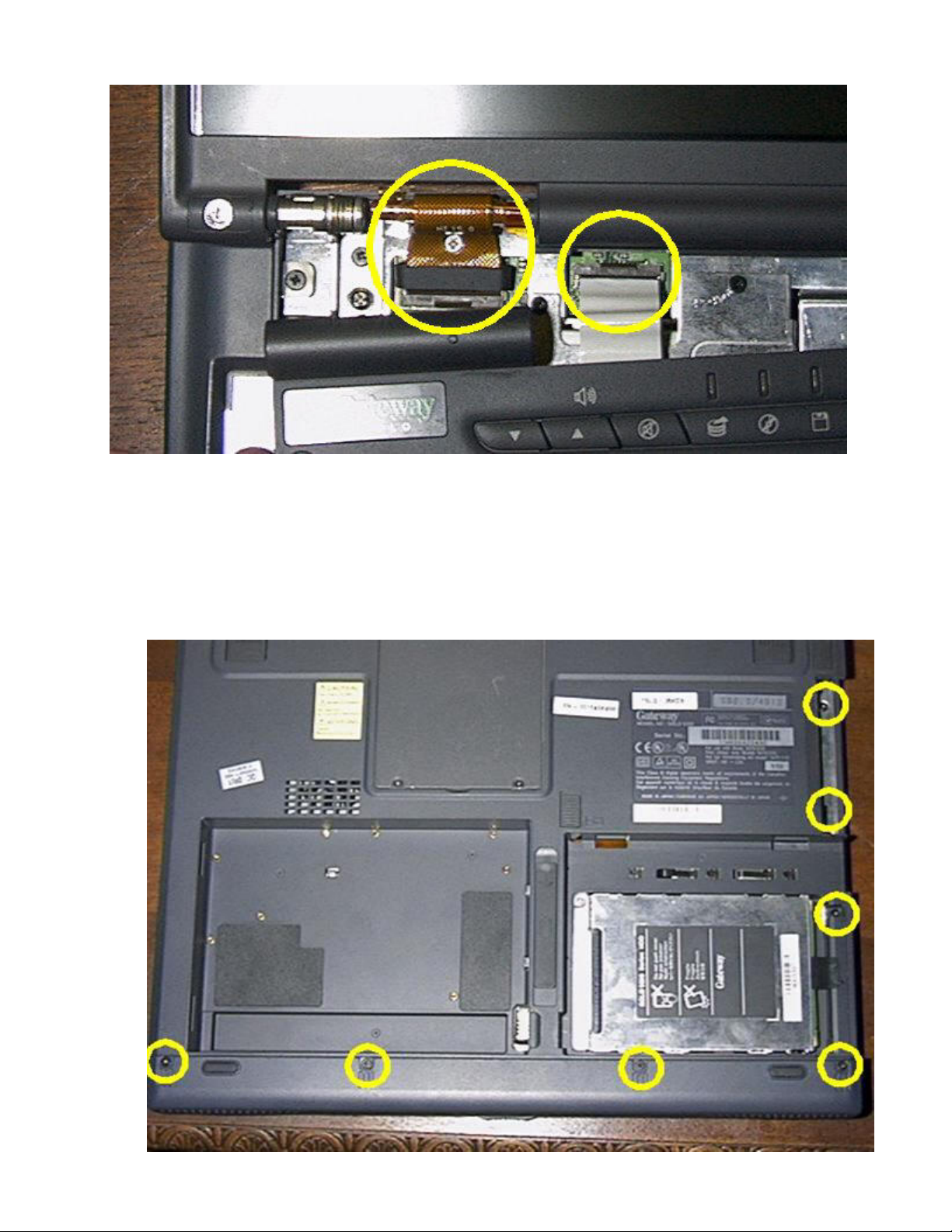
3. Remove On/Off Power LED Bezel.
The bezel is held onto the laptop by three screws. Two are located to the left and right
sides of the bezel and are located under black plastic covers. The third is located in the
middle and screws into the heat sink/fan assembly.
4. Lift off “On/Off Bezel”.
The bezel may take a little bit of prying to get off the laptop. The LCD screen will have
to be lowered to a flat level. Take care when separating the bezel from the chassis as
10/2/21, 10:04 AM
Solo 9300 Assembly
test.leecomputers.com/9300disassembly.htm?fbclid=IwAR0A2pg8Rg5bOAJkNG53Q8njngRJE4gH_Zpo6A8LBkZuLi_xylKNr49AFGs
2/9
the ribbon cable that connects the two is very very fragile and is susceptible to damage.
5. Remove Audio Bar.
The bar is attached via four screws on the bottom of the chassis. Once the screws are
removed the bar comes off with an up and out motion once the chassis is turned over.
Once removed it also makes visible four additional screws that are used to attach the
upper plastic assembly.

10/2/21, 10:04 AM
Solo 9300 Assembly
test.leecomputers.com/9300disassembly.htm?fbclid=IwAR0A2pg8Rg5bOAJkNG53Q8njngRJE4gH_Zpo6A8LBkZuLi_xylKNr49AFGs
3/9
There are also three additional screws that can be removed at this time if the chassis
will be dismantled to actually get to the chassis. After the Audio Bar is removed, it is
fairly easy to determine which screws will need to be removed to access the required
part. I must also note that if the Video board must be changed, the heat sink/fan and
processor will have to be removed.
6. Remove the Heat Sink / Fan Assembly
NOTE: This section is before removal of the LCD screen because I feel
that the processor is the most sensitive portion of laptop and there may be
stray stored energy in the LCD inverter that may potentially cause damage
to the CPU.
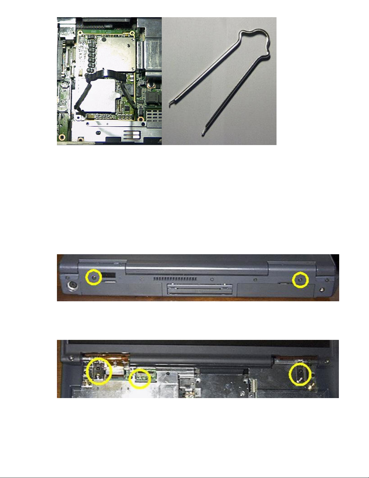
The assembly is secured to the processor by five screws (shown in RED). The
assembly is secured to the chassis by six screws (shown in BLUE). Remove all screws
and lift the assembly up. Gently pull up on the power cable then set the assembly to the
side.
7. Removal of the CPU.
NOTE: Store the CPU in a anti-static bag, if possible
I used a chip puller to remove the CPU. The puller can be found in most computer
toolkits and resembles a set of mini tongs. Looking at the CPU there are white stripes
on either side of where the MMC-2 connector is located. Place the puller on both sides
of the CPU with the puller and gently pull up. Place the CPU in the anti-static bag.
10/2/21, 10:04 AM
Solo 9300 Assembly
test.leecomputers.com/9300disassembly.htm?fbclid=IwAR0A2pg8Rg5bOAJkNG53Q8njngRJE4gH_Zpo6A8LBkZuLi_xylKNr49AFGs
4/9
8. Remove top plastic. (Refer to picture from 6 above)
The top plastic is held in place by eight screws, four of which are visible after the
Audio Bar has been removed. The other four are are located under the touchpad
assembly (2) and on either side of where the LCD hinges attach (2).
9. Remove LCD.
The LCD bezel/lid is held on by six screws. Three on each side, as well as the LVDS
cable connector. Disconnect the LVDS cable prior to removing the screws. The first
set of screws to be removed is the two located on the back of the chassis. These screw
into the LCD hinge and provide support.
The second set is located on the top of the chassis. Also while the On/Off bezel is off
you can determine which Video Board you are using. This one happens to be an “A”.
The LVDS cable will match (and if your building – must match!)
If you are removing the Modem and or Audio board proceed to step 15, if you are removing/replacing the LCD
video board connector continue with Step 10.
10. Remove metal CD/DVD area cover. It is held in place by six screws.

10/2/21, 10:04 AM
Solo 9300 Assembly
test.leecomputers.com/9300disassembly.htm?fbclid=IwAR0A2pg8Rg5bOAJkNG53Q8njngRJE4gH_Zpo6A8LBkZuLi_xylKNr49AFGs
5/9
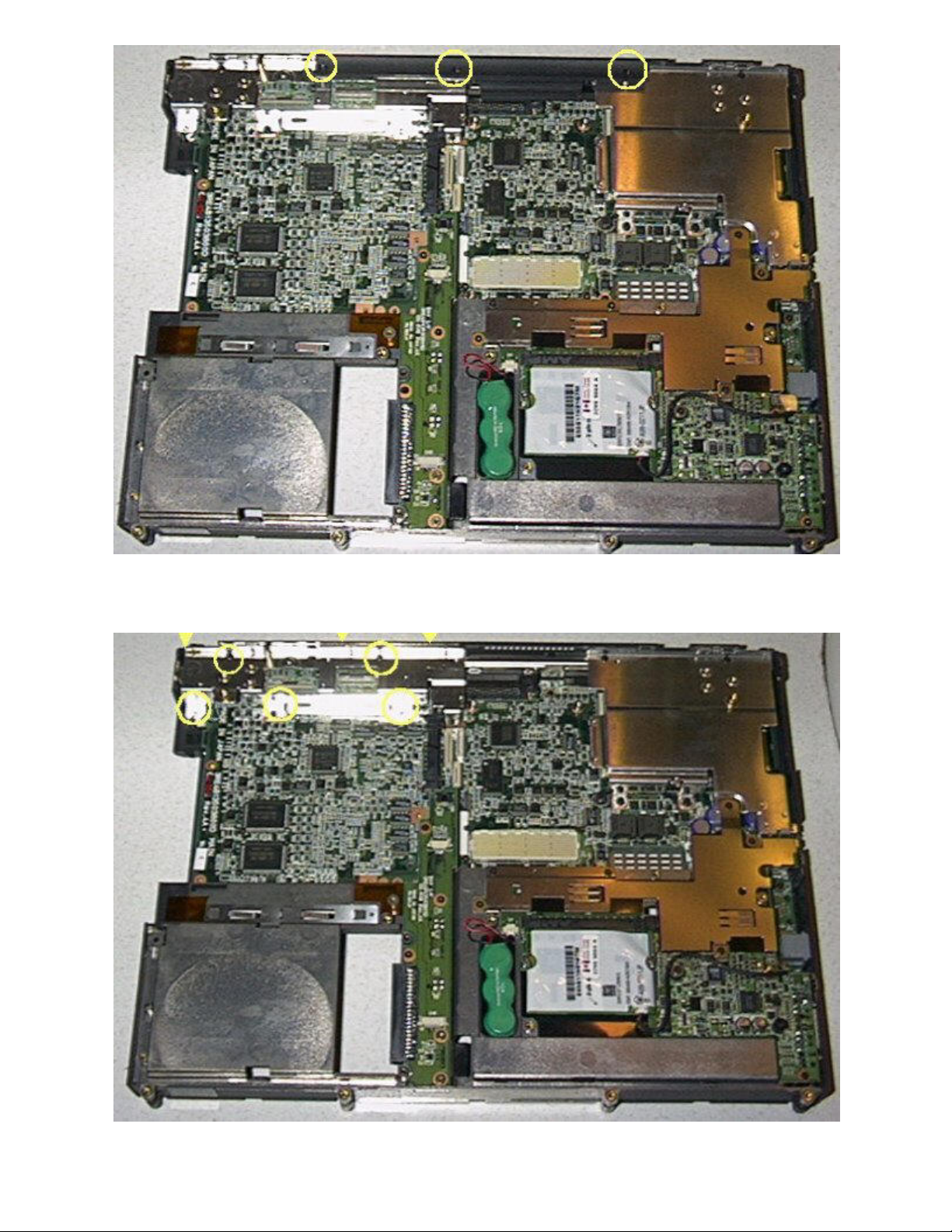
11. Remove metal motherboard area cover. It is held in place by three screws,
12. Remove the bezel plastic. Held in place by three screws.
10/2/21, 10:04 AM
Solo 9300 Assembly
test.leecomputers.com/9300disassembly.htm?fbclid=IwAR0A2pg8Rg5bOAJkNG53Q8njngRJE4gH_Zpo6A8LBkZuLi_xylKNr49AFGs
6/9
13. Remove the LCD mounting bracket. Held in place by eight screws. Three screws are located on the
backside of the chassis (denoted by the yellow triangle).
14. Remove the LCD video adapter board. It is held in place by two screws. Change out for the board you
need, etc.
10/2/21, 10:04 AM
Solo 9300 Assembly
test.leecomputers.com/9300disassembly.htm?fbclid=IwAR0A2pg8Rg5bOAJkNG53Q8njngRJE4gH_Zpo6A8LBkZuLi_xylKNr49AFGs
7/9
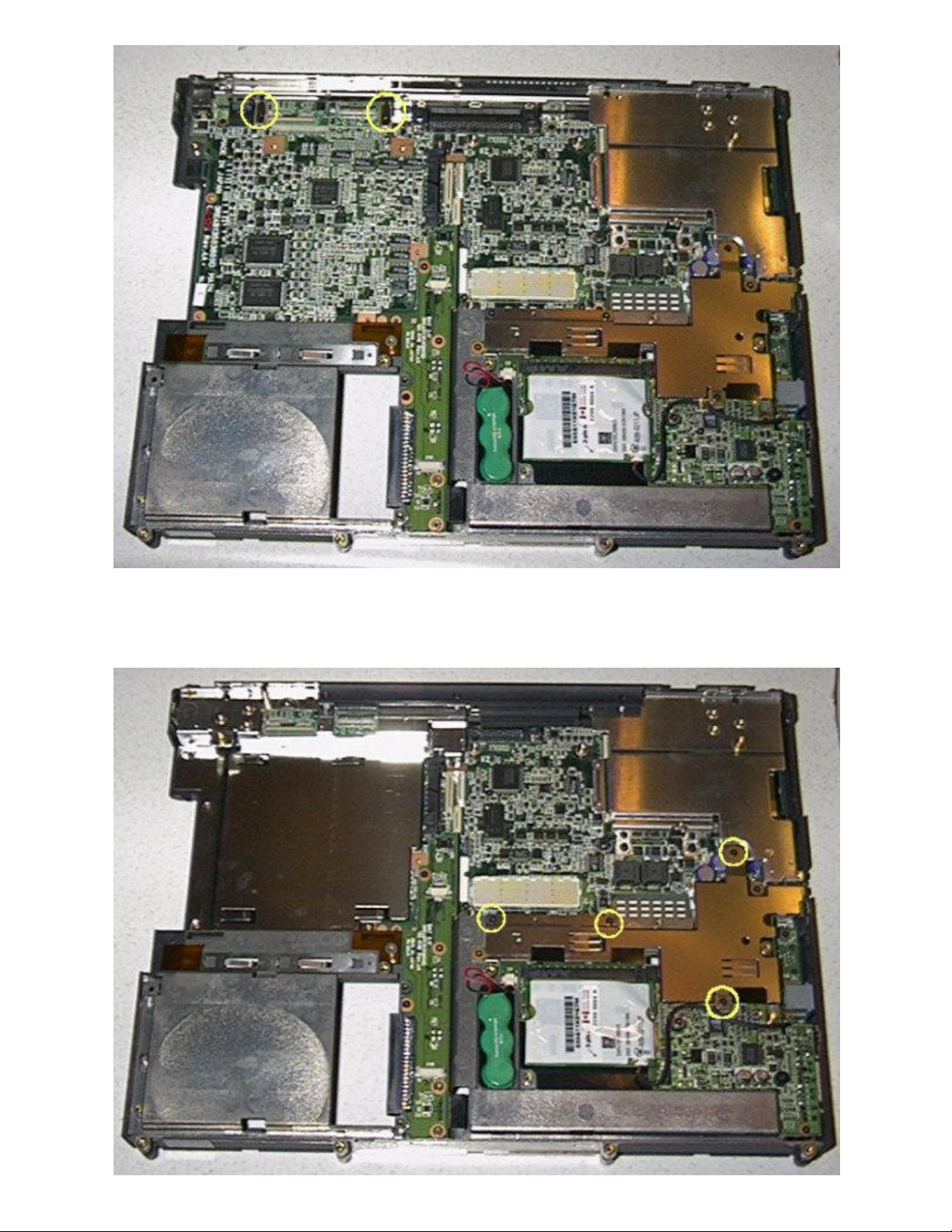
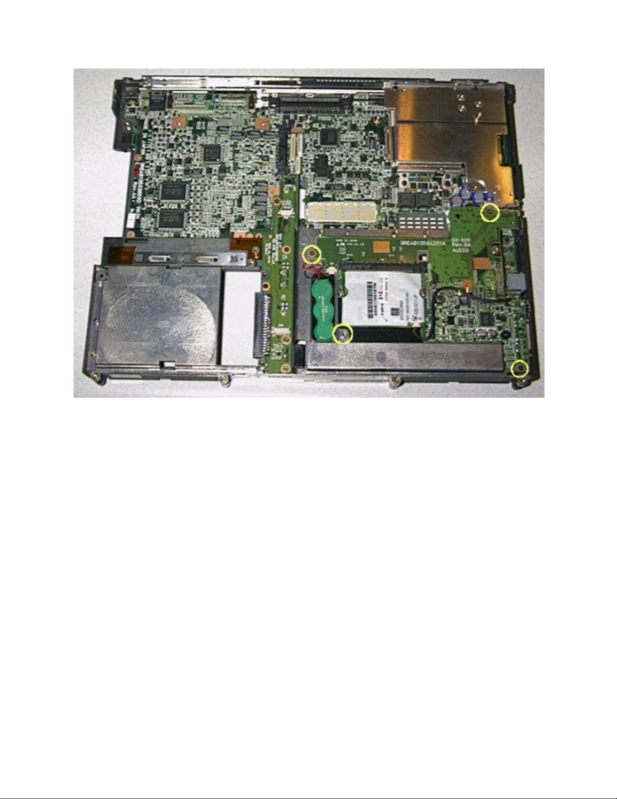
15. Remove of the modem is simple, as it is of the MiniPCI type and can be remove from its connector and
disconnected from the cable. To remove the audio board, first remove the metal board protector. It is held in
place by four screws.
10/2/21, 10:04 AM
Solo 9300 Assembly
test.leecomputers.com/9300disassembly.htm?fbclid=IwAR0A2pg8Rg5bOAJkNG53Q8njngRJE4gH_Zpo6A8LBkZuLi_xylKNr49AFGs
8/9
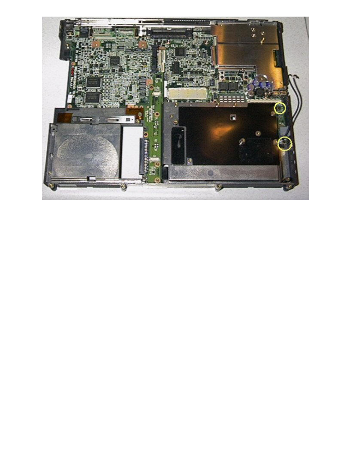
16. Remove the audio board. Held in place by four screws. The audio ports are in through the chassis plastic,
so you may have to wiggle the board to get it removed.
17. Remove the modem/LAN bezel, if desired. It is held in place by two screws. NOTE: to remove the
modem/LAN bezel it is not necessary to remove the audio board. While any MiniPCI board should work in the
slot, Gateway used ActionTec and 3Com MiniPCI modems and 3Com MiniPCI LAN/modem combo cards.
10/2/21, 10:04 AM
Solo 9300 Assembly
test.leecomputers.com/9300disassembly.htm?fbclid=IwAR0A2pg8Rg5bOAJkNG53Q8njngRJE4gH_Zpo6A8LBkZuLi_xylKNr49AFGs
9/9


