EnerSys alpha CXPS-E3 User manual
CXPS-E3 200A - 600A
Power System
User Guide ID: 9400016-J0
Eective: 04/2021
Read this manual carefully.
Learn how to protect your equipment from damage and fully understand its functions.

CXPS-E3 Power System
200A - 600A
Copyright
Copyright © 2021 Alpha Technologies Ltd. All rights reserved. Alpha is a registered trademark of Alpha
Technologies.
No part of this documentation shall be reproduced, stored in a retrieval system, translated, transcribed, or
transmitted in any form or by any means manual, electric, electronic, electromechanical, chemical, optical, or
otherwise without prior explicit written permission from Alpha Technologies.
This document, the software it describes, and the information and know-how they contain constitute the
proprietary, confidential and valuable trade secret information of Alpha Technologies, and may not be used for
any unauthorized purpose, or disclosed to others without the prior written permission of Alpha Technologies.
The material contained in this document is for information only and is subject to change without notice.
While reasonable efforts have been made in the preparation of this document to assure its accuracy, Alpha
Technologies assumes no liability resulting from errors or omissions in this document, or from the use of the
information contained herein. Alpha Technologies reserves the right to make changes in the product design
without reservation and without notification to its users.
Alpha shall not be held liable for any damage or injury involving its enclosures, power supplies,
generators, batteries, or other hardware if used or operated in any manner or subject to any
condition inconsistent with its intended purpose, or if installed or operated in an unapproved
manner, or improperly maintained.
Photographs contained in this manual are for illustrative purposes only. These photographs
may not match your installation.
NOTE
Operator is cautioned to review the drawings and illustrations contained in this manual before
proceeding. If there are questions regarding the safe operation of this powering system, contact
Alpha Technologies or your nearest Alpha representative.
NOTE
NOTE
For technical support, contact Alpha Technologies:
Canada and USA: +1.888.462.7487
International: +1.604.436.5547
Email: [email protected]

9400016-J0 Rev E
2
User Guide
CXPS-E3
Contents
1. Safety..............................................................................................6
1.1 Safety symbols........................................................................................................................... 6
1.2 General safety............................................................................................................................ 6
1.3 Electrical safety.......................................................................................................................... 7
1.4 Battery safety ............................................................................................................................. 7
2. Introduction .....................................................................................8
2.1 Scope of the manual .................................................................................................................. 8
2.2 Product overview ....................................................................................................................... 8
2.3 System congurations................................................................................................................ 9
3. Specications................................................................................12
4. Features........................................................................................14
4.1 Seismic racks........................................................................................................................... 14
4.2 Distribution centers .................................................................................................................. 14
4.3 Front panel with a Cordex HP controller .................................................................................. 16
4.4 L-ADIO ..................................................................................................................................... 17
4.5 2.4kW rectier .......................................................................................................................... 19
4.6 3.0kW rectier .......................................................................................................................... 19
4.7 4.0kW rectier .......................................................................................................................... 19
4.8 4.6kW rectier .......................................................................................................................... 19
4.9 Rectier front panel LEDs ........................................................................................................ 20
4.10 400A LVD override ................................................................................................................ 21
4.11 600A LVD override ................................................................................................................. 23
4.12 Integrated battery trays .......................................................................................................... 26
4.13 Battery landing busbar kit ...................................................................................................... 26
5. Inspection......................................................................................28
5.1 Packing materials..................................................................................................................... 28
5.2 Check for damage.................................................................................................................... 28
5.3 General receipt of shipment..................................................................................................... 28
6. Installation.....................................................................................29

39400016-J0 Rev E
CXPS-E3User Guide
6.1 Safety precautions ................................................................................................................... 29
6.2 Tools required .......................................................................................................................... 29
6.3 Installation of external batteries ............................................................................................... 29
6.4 Battery maintenance report...................................................................................................... 31
6.5 Power system assembly and mounting ................................................................................... 32
6.6 Breaker installation .................................................................................................................. 34
7. Wiring............................................................................................35
7.1 Installation notes ...................................................................................................................... 35
7.2 Grounding ................................................................................................................................ 36
7.3 AC wiring.................................................................................................................................. 39
7.4 DC wiring ................................................................................................................................. 40
7.5 Distribution cabling................................................................................................................... 41
7.6 Alarm and signal connection .................................................................................................... 42
7.7 Network and remote communication ....................................................................................... 43
7.8 Connecting battery temperature probes .................................................................................. 43
7.9 Signal wiring............................................................................................................................. 44
8. System startup..............................................................................45
9. Maintenance .................................................................................47
9.1 400A LVD override operation ................................................................................................... 48
9.2 600A LVD override operation ................................................................................................... 48
10. Acronyms and denitions............................................................49
11. Warranty statement and service information...............................50
11.1 Technical support ................................................................................................................... 50
11.2 Warranty statement ................................................................................................................ 50
11.3 Product warranty .................................................................................................................... 50
11.4 Battery warranty ..................................................................................................................... 50
11.5 Warranty claims...................................................................................................................... 50
11.6 Service information ................................................................................................................ 50
12. Certication.................................................................................51

9400016-J0 Rev E
4
User Guide
CXPS-E3
Figures
Figure 1 — CXPS-E3 system ........................................................................................................... 8
Figure 2 — 19 inch CXPS-E3 with 2.4kW | 3.0kW rectiers............................................................. 9
Figure 3 — 23 inch CXPS-E3 with 2.4kW | 3.0kW rectiers........................................................... 10
Figure 4 — 19 inch CXPS-E3 with 4.0kW | 4.6kW rectiers........................................................... 10
Figure 5 — 23 inch CXPS-E3 with 4.0kW | 4.6kW rectiers............................................................11
Figure 6 — 23 inch CXPS-E3 with 3.0kW rectiers .........................................................................11
Figure 7 — Front panel with L-ADIO and Cordex HP controller ..................................................... 16
Figure 8 — Cordex HP controller.................................................................................................... 16
Figure 9 — L-ADIO IO peripheral ................................................................................................... 18
Figure 10 — LVD override............................................................................................................... 21
Figure 11 — LVD override interface ................................................................................................ 21
Figure 12 — LVD override connections .......................................................................................... 22
Figure 13 — Integrated battery tray ................................................................................................ 26
Figure 14 — Battery landing busbar kit........................................................................................... 27
Figure 15 — Rack mounting details (top view), welded rack .......................................................... 33
Figure 16 — Rack mounting details (top view), bolted rack............................................................ 33
Figure 17 — Breaker installation..................................................................................................... 34
Figure 18 — Connecting the frame ground to the CXPS-E3 .......................................................... 37
Figure 19 — Connecting the frame ground to overhead trays........................................................ 37
Figure 20 — AC input and ground for 23inch shelf ......................................................................... 39
Figure 21 — Shelf AC connection (three-phase, three-wire shown with back cover removed) ...... 40
Figure 22 — Alarm (relay) connections........................................................................................... 42
Figure 23 — Digital input connection method ................................................................................. 42
Figure 24 — Battery temperature probes ....................................................................................... 43
Figure 25 — Battery temperature probes, battery bay.................................................................... 43
Figure 26 — Relay connections, not energized state ..................................................................... 44
Figure 27 — Alarm relay pinouts..................................................................................................... 44

59400016-J0 Rev E
CXPS-E3User Guide

9400016-J0 Rev E
6
User Guide
CXPS-E3
1. Safety
Save these instructions
This manual contains important safety instructions that must be followed during the installation, servicing, and
maintenance of the product. Keep it in a safe place. Review the drawings and illustrations contained in this
manual before proceeding. If there are any questions regarding the safe installation or operation of this product,
contact Alpha Technologies or the nearest Alpha representative.
1.1 Safety symbols
To reduce the risk of injury or death, and to ensure the continued safe operation of this product, the following
symbols have been placed throughout this manual. Where these symbols appear, use extra care and attention.
The use of ATTENTION indicates specific regulatory/code requirements that may affect the placement of
equipment and /or installation procedures.
WARNING!
WARNING presents safety information to PREVENT INJURY OR DEATH to personnel. Warnings
are indicated by a shock hazard icon, the word WARNING, and a rule beneath which the
information appears.
WARNING!
You must read and understand the following warnings before installing the enclosure and its
component. Failure to do so could result in personal injury or death.
CAUTION!
CAUTION indicates safety information intended to PREVENT DAMAGE to material or equipment.
Cautions are designated with a yellow warning triangle, the word CAUTION, and a rule beneath
which the information appears.
NOTE
are designated with a checkmark, the word NOTE, and a rule beneath which the information
appears
HOT!
The use of HOT presents safety information to PREVENT BURNS to the technician or user.
1.2 General safety
• Read and follow all instructions included in this manual.
• Only trained personnel are qualied to install or replace this equipment and its components.
• Use proper lifting techniques whenever handling equipment, parts, or batteries.

79400016-J0 Rev E
CXPS-E3User Guide
1.3 Electrical safety
WARNING!
WARNING!
WARNING!
Before working with any live battery or power system, follow these precautions:
a. Remove all metallic jewelry, such as watches, rings, metal rimmed glasses, or necklaces.
b. Wear safety glasses with side shields at all times during the installation.
c. Use OSHA (or international equivalent) approved insulated hand tools.
Lethal voltages are present within the power system. Always assume that an electrical
connection or conductor is energized. Check the circuit with a voltmeter with respect to the
grounded portion of the enclosure (both AC and DC) before performing any installation or
removal procedure.
• Do not work alone under hazardous conditions.
• A licensed electrician is required to install permanently wired equipment. Input voltages can range up to
480 Vac. Ensure that the utility power is disconnected and locked out before performing any installation
or removal procedure.
• Ensure that no liquids or wet clothes come into contact with internal components.
• Hazardous electrically live parts inside this unit are energized from the batteries even when the AC input
power is disconnected.
Follow battery manufacturer’s safety recommendations when working around battery systems.
charging. When charging, batteries vent hydrogen gas, which can explode.
Batteries are hazardous to the environment and should be disposed at a recycling facility. Consult the battery
manufacturer for recommended local authorized recyclers.
and batteries, though not dangerous in voltage, has a high short-circuit current capacity that
may cause severe burns and electrical arcing.
WARNING!
High leakage current, earth connection essential before connecting the supply.
1.4 Battery safety
• Servicing and connection of batteries must be performed by, or under the direct supervision of, personnel
knowledgeable of batteries and the required safety precautions.
• Always wear eye protection, rubber gloves, and a protective vest when working near batteries. Remove
all metallic objects from your hands and neck.
• Use OSHA (or international equivalent) approved insulated hand tools. Do not rest tools on top of
batteries.
• Batteries contain or emit chemicals known to cause cancer and birth defects or other reproductive harm.
Battery post terminals and related accessories contain lead and lead compounds. Wash your hands after
9400016-J0 Rev E
8
User Guide
CXPS-E3
2. Introduction
2.1 Scope of the manual
This manual covers the features, options, installation, and startup of Alpha Technologies CXPS-E3 power
system. Images contained in this document are for illustrative purposes only and may not exactly match your
installation. To assist with installation, refer to the drawings at the end of this manual.
In addition to this manual, the following documents may be included in the documentation package that ships with
the CXPS-E3:
• Cordex HP Controller Software manual: 0350058-J0
• Cordex HP Controller and IO Peripherals Hardware manual: 0180036-J0
• Cordex 48-2.4kW Rectier and Shelf manual: 0300040-J0
• Cordex 48-3.0kW Rectier and Shelf manual: 0100037-J0
• Cordex 48-4.0kW | 4.6kW Rectier and Shelf manual: 9400000-J0
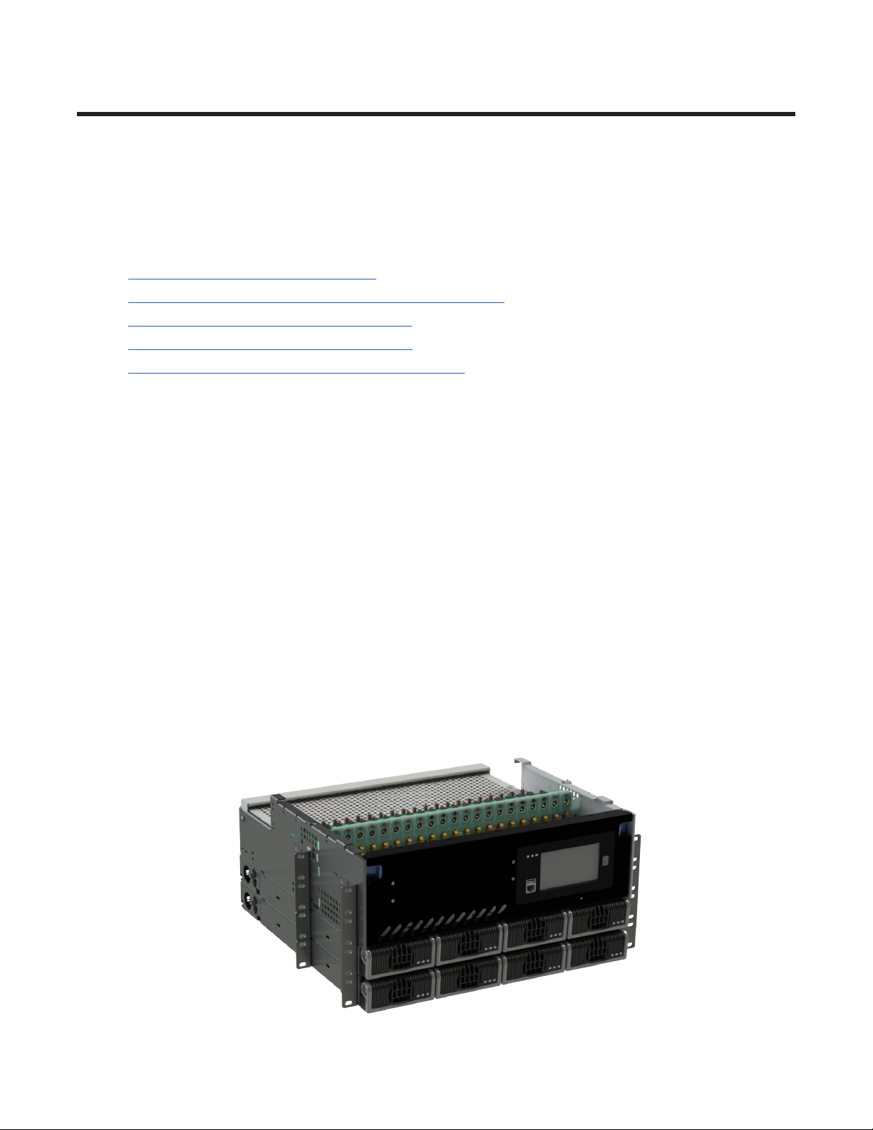
2.2 Product overview
The CXPS-E3 uses high-density rectifiers, a front access distribution center, and the advanced Cordex HP
controller. The CXPS-E3 is the ideal solution for small to medium-sized 48Vdc applications, providing up to 600
Amps of output current. With universal 19" or 23" mounting, high temperature operation, and high power density,
it is the perfect solution for a wide variety of installation scenarios including those in harsh, outdoor environments.
The distribution center provides up to 26 load breaker positions, integrated shunt, and optional low-voltage
battery disconnect (LVBD). All distribution connections and controller IO contacts are front accessible.
The Cordex HP controller includes a touch screen display for simple and convenient local setup. A built-in web
server provides alternate setup via local or remote IP access, using a standard internet browser. The CXPS-E3
can be easily integrated into customer-provided relay racks or enclosures, or can be ordered factory installed into
various Alpha relay rack configurations, including systems with pre-wired battery trays.
• Integrated 48V, 600A power system with front access distribution
• Industry leading power system density
• Up to 600A, 26 distribution positions in 5RU
• Advanced Cordex HP controller with touch screen display for full local control
• High temperature rated design for harsh outdoor applications
• Wide range AC input for exible worldwide deployment
Figure 1 — CXPS-E3 system

99400016-J0 Rev E
CXPS-E3User Guide
2.3 System congurations
The following five configurations are currently available for the CXPS-E3 power system. For more ordering
information, refer to the CXPS-E3 Ordering Guide on the Alpha website.
Table A —
Rack size Controller Expanded
IO
Current
rating
Load
breakers
Battery
breakers
Shunt LVBD
(optional)
Height
19" CXC HP L-ADIO 400A 8× 2.4kW | 3.0kW
(2 shelves)
21 0 Load No 5 RU
16 5 Battery LVBD 5 RU
23" CXC HP L-ADIO 400A 10× 2.4kW | 3.0kW
(2 shelves)
26 0 Load No 5 RU
21 5 Battery LVBD 5 RU
19" CXC HP L-ADIO 400A 5× 4.0kW | 4.6kW
(1 shelf)
21 0 Load No 7 RU
16 5 Battery LVBD 7 RU
23" CXC HP L-ADIO 400A 6× 4.0kW | 4.6kW
(1 shelf)
26 0 Load No 7 RU
21 5 Battery LVBD 7 RU
23" CXC HP L-ADIO 600A 10× 2.4kW | 3.0kW
(2 shelves)
26 0 Battery No 5 RU
26 0 Battery LVBD 5 RU
2.3.1 CXPS-E3 19inch systems with 2.4kW | 3.0kW rectiers
• Rated for 400A with two 2.4kW | 3.0kW shelves
• 5RU with two 2.4kW | 3.0kW shelves
• 21 load breakers with load shunt or 16 load and 5 battery breakers with LVBD
• Cordex HP controller
• L-ADIO module with extensive IO capability
• Option for LVBD for battery breaker conguration
Figure 2 — 19 inch CXPS-E3 with 2.4kW | 3.0kW rectifiers

9400016-J0 Rev E
10
User Guide
CXPS-E3
2.3.3 CXPS-E3 19 inch systems with 4.0kW | 4.6kW rectiers
• Rated for 400A with one 4.0kW | 4.6kW shelf
• 7RU with one 4.0kW | 4.6kW shelf
• 21 load breakers with load shunt or 16 load and 5 battery breakers with LVBD
• Cordex HP controller
• L-ADIO module with extensive IO capability
• Option for LVBD for battery breaker conguration
Figure 4 — 19 inch CXPS-E3 with 4.0kW | 4.6kW rectifiers
2.3.2 CXPS-E3 23 inch systems with 2.4kW | 3.0kW rectiers
• Rated for 400A with two 2.4kW | 3.0kW shelves
• 5RU with two 2.4kW | 3.0kW shelves
• 26 load breakers with load shunt or 21 load and 5 battery breakers with LVBD
• Cordex HP controller
• L-ADIO module with extensive IO capability
• Option for LVBD for battery breaker conguration
Figure 3 — 23 inch CXPS-E3 with 2.4kW | 3.0kW rectifiers

119400016-J0 Rev E
CXPS-E3User Guide
2.3.4 CXPS-E3 23 inch systems with 4.0kW | 4.6kW rectiers
• Rated for 400A with one 4.0kW | 4.6kW shelf
• 7RU with one 4.0kW | 4.6kW shelf
• 26 load breakers with load shunt or 21 load and 5 battery breakers with LVBD
• Cordex HP controller
• L-ADIO module with extensive IO capability
• Option for LVBD for battery breaker conguration
• Option for dierent AC input congurations individual feed, 208 three phase 480/277 three phase
Figure 5 — 23 inch CXPS-E3 with 4.0kW | 4.6kW rectifiers
2.3.5 CXPS-E3 23 inch systems with 3.0kW rectiers
• Rated for 600A with two 3.0kW shelves
• 5RU with two 3.0kW shelves
• 26 load breakers with load shunt or 26 load breakers with battery shunt and LVBD
• Cordex HP controller
• L-ADIO module with extensive IO capability
Figure 6 — 23 inch CXPS-E3 with 3.0kW rectifiers

9400016-J0 Rev E
12
User Guide
CXPS-E3
3. Specifications
Table B — 48V–2.4kW | 3.0kW, 4.0kW | 4.6kW 400A CXPS-E3 systems
Electrical
48V, 2.4kW | 3.0kW 48V, 4.0kW | 4.6kW
System capacity (max.) 400A 400A
Input
Operating voltage 208 to 277Vac (nominal) 208 to 277Vac (nominal)
Extended (high) 277 to 310Vac 277 to 310Vac
Extended (low)
90 to 187Vac (de-rated O/P power) 90 to 187Vac (de-rated O/P power)
Recommended AC
breakers
19" system: Up to 8× 20A feeds
23" system: Up to 4× 40A feeds &
2× 20A feeds
19" system: Up to 5
×
30A feeds
(208-277single phase)
23" system: Up to 6
×
30A feeds
(208-277single phase)
Up to 2
×
50A feeds (208 three
phase)
Up to 2
×
30A feeds (480/277 three
phase)
Eciency >96% Peak eciency >95% Peak eciency
Output Rectier positions 19" system: Up to 8 rectiers
23" system: Up to 10 rectiers
19" system: Up to 5 rectiers
23" system: Up to 6 rectiers
Mechanical
19" system
Mounting Flush/center Flush/center
Dimensions (H × W × D) 8.75" × 19" × 17.4" 12.25" × 19" × 16.6"
Hot positions
21× load breakers (or) 16 load
+ 5 battery breakers
21× load breakers (or) 16 load
+ 5 battery breakers
21× sets of 1/4" studs on 5/8"
centers
21× sets of 1/4" studs on 5/8"
centers
Return Positions 21× sets of 1/4" studs on 5/8"
centers
21× sets of 1/4" studs on 5/8"
centers
Weight (System) 20.4kg (45lbs) 20kg (44lbs)
23" system
Mounting Flush/center Flush/center
Dimensions (H × W × D) 8.75" × 23" × 17.4" 12.25" × 23" × 17.75"
Hot Positions
26× load breakers (or) 21 load
+ 5 battery breakers
26× load breakers (or) 21 load
+ 5 battery breakers
26× sets of 1/4" studs on 5/8"
centers
26× sets of 1/4" studs on 5/8"
centers
Return Positions 26× sets of 1/4" studs on 5/8"
centers
26× sets of 1/4" studs on 5/8"
centers
Weight (System) 25.8kg (57lbs) 22.7kg (50lbs)
1.76kg (3.9lbs) per module 3.9kg (8.6lbs) per module
System access Front access after initial installation
Controller Cordex HP
Environmental
Temperature -40 to 55°C (-40 to 131°F) 4.6kW derated at 40°C
55 to 65°C (-40 to 149°F) de-rated output
Humidity 0 to 95% RH non-condensing
Elevation -500 to 2000m (-1640 to 6600ft)
-500 to 4000m (-1640 to 13100ft) with de-rated output
Compliance
Safety CSA C22.2 No. 60950-1-07
UL 60950-1

139400016-J0 Rev E
CXPS-E3User Guide
Table C — 48V–3.0kW 600A systems
Electrical
System Capacity (max)
Systems with LVBD Systems without LVBD
Amperage
625A total
550A load
550A battery
625A total
Input
Operating voltage 208 to 277Vac (nominal)
Extended (high) 277 to 310Vac
Extended (low)
90 to 187Vac (de-rated O/P power)
Recommended AC
breakers 23" system: Up to 4× 40A feeds & 2× 20A Ffeeds
Eciency >96% peak eciency
Output
Current per module
(nominal input)
62.5A at 48Vdc
55.5A at 54Vdc
Rectier positions 23" system: up to 10 rectiers
Mechanical
23" system
Mounting Flush/center
Dimensions (H × W × D) 10.1" × 23" × 19.5"
Hot positions 26× load breakers 26x sets of ¼" studs on 5/8" centers
Return positions 26× sets of 1/4" studs on 5/8" centers
Weight (system) 27.2kg (60lbs)
1.76kg (3.88lbs) per module
System access Front access after initial installation
Controller Cordex HP
Environmental
Temperature -40 to 55°C (-40 to 131°F)
55 to 65°C (-40 to 149°F) de-rated output
Humidity 0 to 95% RH non-condensing
Elevation -500 to 2000m (-1640 to 6600ft)
Compliance
Safety CSA C22.2 No. 60950-1-07
UL 60950-1

9400016-J0 Rev E
14
User Guide
CXPS-E3
4. Features
4.1 Seismic racks
The CXPS-E3 system can be installed in a variety of Alpha provided, 19" and 23" seismic racks. These racks
have been Z4 rated and NEBS L3 certified. The racks vary in their Z4 seismic capabilities from 500lb to 2500lb
and in their heights from a 3.5' to 9' (standard 7' racks are available as well). For more ordering information, refer
to the CXPS-E3 Ordering Guide (0470209-00) on the Alpha website.
19" or 23" seismic rack
4.2 Distribution centers
The CXPS-E3 power system has been designed with high density breaker or fuse count for use in 48V
applications and is rated for a total ampacity of 400A or 600A. It is available either in a 19" or 23" configuration.
All systems include a back top cover for the protection of live customer connections.
4. 2.1 400A 19inch power center
Provides up to 21 breakers which can be configured as all load breakers (21 load breakers) or a mix of load and
battery breakers (16 load breakers and 5 battery breakers).
The all load breaker configurations have a shunt that monitors the total load current supplied by the rectifiers to
the load.
Both load and battery hot and return connections are made on 1/4" studs on 5/8" centers using narrow tongue
lugs. Adapter kits for landing larger cables are available when higher capacity 2 or 3 pole breakers are required.

159400016-J0 Rev E
CXPS-E3User Guide
4.2.2 400A 23inch power center
Provides up to 26 breakers which can be configured as all load breakers (26 load breakers) or a mix of load and
battery breakers (21 load breakers and 5 battery breakers).
The all load breaker configuration has a shunt that monitors the total load current supplied by the rectifiers to the
load.
The load and battery configuration has a shunt that monitors the total battery charge and discharge current and
includes a low voltage battery disconnect (LVBD).
Both the hot and return connections are made on ¼" studs on 5/8" centers using narrow tongue lugs. Adapter
kits for landing larger cables are available when higher capacity 2 or 3 pole breakers are required.
4.2.3 600A 23inch power center
Provides up to 26 load breakers with configurable battery landing outputs. The all load breaker configuration
has a shunt that monitors the total load current supplied by the rectifiers to the load. The low voltage battery
disconnect configuration has a shunt that monitors the total battery charge and discharge current and includes a
low voltage battery disconnect (LVBD).
Both the hot and return connections are made on ¼" studs on 5/8" centers using narrow tongue lugs. Adapter kits
for landing larger cables are available when higher capacity 2 or 3 pole breakers are required.
4.2.4 Control and monitoring methods
The CXPS-E3 front panel provides inputs and outputs for load and battery voltage, battery or load current,
breaker alarms and disconnect control as well as monitoring. Additional IO (expansion) is available for customer
use. See the following table for the details.
Table D — Control and monitoring methods
Features
L-ADIO
Dedicated IO: Bus voltage monitoring (2)
Breaker alarm monitoring (2)
Dry contact– breaker alarm (2)
Bus voltage sense (2)
Expansion IO
(customer use):
Temperature sensor inputs (4)
Form C relay outputs (12)
Digital inputs (6)
Voltage sense Inputs (2)
Current shunt Inputs (4)
Cordex HP controller
Local connection to L-ADIO
Advanced UI
Ethernet connection
4.2.5 Breaker labelling
For systems with load only outputs, the numbering goes from left (1) to right ( 21 for a 19" or 26 for a 23")
For systems with batteries and loads the load numbering goes from left (1) to center/right (16 for a 19" or 21 for a
23") and the battery labelling goes from right (1) to left (5).
There is a label on top of the front door which can be seen from the top when the door is closed, and from the
front when the door is open. This label is larger and suitable for writing information about the breaker position.
There are two additional labels for breaker identification: a thin label above the breaker which can be read from
the front (not writable), and one on the back/top near the return breakers which identify the positions of the return
(not writable).

9400016-J0 Rev E
16
User Guide
CXPS-E3
4.3 Front panel with a Cordex HP controller
The front panel includes the Cordex HP controller and a pre-wired L-ADIO module.
The Cordex HP family of products provide centralized setup, control and monitoring of power systems. This can
range from simple monitoring and threshold alarms for temperature, voltage and current, to advanced battery
charging and diagnostic features. The controller has a 4.3-inch, full color touch screen display.
The Cordex HP provides dual Ethernet ports allowing for simultaneous network, LCD and local laptop access to
the controller including both web and SNMP interfaces.
The Cordex HP supports dual CAN ports to allow up to 254 power and/or ADIO modules to be controlled and
monitored. The Cordex HP uses external analog and digital input and output (ADIO) peripherals to monitor
electrical signals (for example temperature, voltage) and generate electrical signals through relays.
Detailed operation of the controller is provided in the Cordex HP software manual.
The most commonly used ADIO peripheral is the L-ADIO for low voltage systems which includes:
• 8 digital inputs
• 4 voltage sensors
• 4 temperature sensors
• 4 current sensors
• 12 Form C relay outputs
Figure 7 — Front panel with L-ADIO and Cordex HP controller
Ethernet
(rear
USB (rear)
USB (front)
Ethernet (front)
Status LEDsLCD screen
Home
Reset
Figure 8 — Cordex HP controller

179400016-J0 Rev E
CXPS-E3User Guide
The Cordex HP has the following features:
Front touch screen Full color LCD touch screen display, to access controls and menu items by using
ngertip touch or a stylus.
Home button Provides the ability to go directly back to the home screen from any menu.
Front panel reset For emergency use only to restart the Cordex HP if the unit touch screen or home
button are not responding.
Front panel LEDs For alarms, progress and status indication.
Audio speaker Built-in audio speaker tones during active alarms and can be disabled if required.
Dual Ethernet ports 10/100BASE-T Ethernet connection on both the front and back of the controller for
remote or local communication.
USB Dual ports on both the front and back of the controller for upgrades or le
management via a standard USB ash drive.
CAN Dual independent CAN bus ports for communication with the Cordex and AMPS
family of products, allowing for a greater number of devices.
Real-time clock With eld replaceable lithium battery, allows for timestamps on alarms and events.
System fail alarm/relay Which activates when there is a major internal failure. During such a condition the
unit attempts to reset.
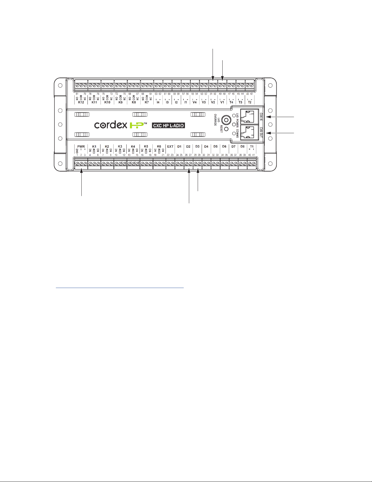
4.4 L-ADIO
4.4.1 Analog input channels
The controller is supplied with analog input channels for voltage, current, and temperature.
4.4.2 Voltage inputs
Two voltage input channels, V1 and V2, are used to monitor the discharge and charge voltage. V1 for Bus A
Voltage and V2 for Bus B Voltage. Voltage inputs V3 and V4 are not used in the CXPS-E3 and are available for
customer use.
4.4.3 Temperature inputs
The CXPS-E3 panel can accept up to four temperature probes to monitor the surrounding ambient temperatures.
These analog values can be used to report high or low temperature alarms.
4.4.4 Digital input channels
The CXPS-E3 panel can accept up to eight digital inputs. Digital Inputs D1 and D2 are wired for Bus 'A' Breaker
Alarm and Bus 'B' Breaker Alarm respectively. Digital inputs D3 to D8 are available for customer use.
4.4.5 Alarm and control output relays
The controller contains 12 Form C digital alarm output relays, that are used to extend alarms and control to
external apparatus. Each internally generated alarm or control signal may be mapped to any one of these relays,
or several signals may be mapped to just one relay or none at all. None of the output relays are pre-configured on
the (K1-K12) are available for customer use.
9400016-J0 Rev E
18
User Guide
CXPS-E3
4.4.6 Network connection and remote communications
The system can be set up, monitored, and tested via an Ethernet 10/100 Base-T serial data connection. The
communication protocol supports a web interface. A CAN bus is used to transmit all alarm and control functions
between the controller and rectifiers.
Refer to Cordex HP System Controller Software Manual (0350058-J0) for operation of controller.
4.4.7 Front panel wiring notes
The terminal blocks on the indicator boards are suitable for #26-16AWG wire. As both signals are low current, it is
recommend to use thinner wire were possible to make routing easier and to minimize space consumed by in the
system. This is especially important with the L-ADIO if many of the expansion IO capabilities are to be used.
Added wiring should be routed along the same path as the bus connection cable and then extend through the
back of the unit. Take care to restrain the wiring sufficiently while providing enough slack so as not to interfere
with operation of the door. Use the cable tie locations on the L-ADIO to restrain the cables within the front panel,
and use the lance features on the chassis side panels to guide the cabling to the back of the unit.
Figure 9 — L-ADIO IO peripheral
CAN Ports
CAN Ports
Power Input Bus B Alarm
Bus B Voltage
Bus A Alarm
Bus A Voltage

199400016-J0 Rev E
CXPS-E3User Guide
4.5 2.4kW rectier
4.5.1 Rectier features
• High performance compact 50A rectier for 48Vdc telecom applications
• High eciency (96 +%) for reduced OPEX and carbon footprint
• High temperature operating range for installation in non-controlled environments
• Multiple congurations providing 250A or 12kW in a compact 1RU shelf
• High power density (28W/in3) yields more space for revenue generating equipment
• Wide AC input operating range for global installation requirements
• Extended operating temperature range up to 75°C for deployment in the harshest outdoor environments
4.6 3.0kW rectier
4.6.1 Rectier features
• High performance compact 62.5A rectier for 48Vdc telecom applications
• High eciency (96.2 +%) for reduced OPEX and carbon footprint
• High temperature operating range for installation in non-controlled environments
• Multiple congurations providing 312.5A or 15kW in a compact 1RU shelf
• High power density (35W/in³) yields more space for revenue generating equipment
• Wide AC input operating range for global installation requirements
• Extended operating temperature range up to 75°C for deployment in the harshest outdoor environments
4.7 4.0kW rectier
4.7.1 Rectier features
• High performance 83.3A rectier for 48V telecom applications
• 95.3% eciency for increased OPEX savings and reduced carbon footprint
• High power density 4RU compact design delivering up to 24kW per 23 inch shelf
• Power limiting and wide range AC input for global installation requirements
• Extended operating temperature range up to 75°C for deployment in the harshest outdoor environments
4.8 4.6kW rectier
4.8.1 Rectier features
• High performance 95.8A rectier for 48V telecom applications
• 95.3% eciency for increased OPEX savings and reduced carbon footprint
• High power density 4RU compact design delivering up to 27.6kW per 23 inch shelf
• Power limiting and wide range AC input for global installation requirements
• Extended operating temperature range up to 75°C for deployment in the harshest outdoor environments
Table of contents
Other EnerSys Power Supply manuals

EnerSys
EnerSys alpha APX3-G Series User manual

EnerSys
EnerSys Alpha Broadband UPS User manual

EnerSys
EnerSys Alpha XRT-TPPL User manual

EnerSys
EnerSys alpha Cordex CXRF 48-3.6kW Quick start guide

EnerSys
EnerSys alpha LPS36 Quick start guide

EnerSys
EnerSys alpha APX3 Series User manual

EnerSys
EnerSys Alpha FMPS FTTP User manual


