Solon Blue 230/07 User manual

TechnicalService
asat:08.07.2009 phone: +49 30 81879 0 fax: +49 30 81879 9999 www.solon.com
ASSEMBLY INSTRUCTIONS
S O L O N
STANDARD MODULES
SOLON Blue 230/07
SOLON Black 230/07 (01, 02)
SOLON Blue 220/03 (01, 07)
SOLON Black 280/10
SOLON Black 300/10
SOLON P220/6+/07
SOLON M230/6+/07 (01)
SOLON P220/6+
SOLON M230/6+
SOLON P180/6+
SOLON P130/6+
SOLON SE
Am Studio 16
12489 Berlin
phone:+4930–818790
fax: +4930–818799999
www.solon.com
TechnicalService
asat:08/07/2009 phone: +49 30 81879 0 fax: +49 30 81879 9999 www.solon.com 2
Contents of the Assembly Instructions for Standard Modules by the SOLON SE
Assembly Instructions SOLON Standard Modules
Assembly Instructions - Abstract
Annex 1
Snow Load on the Ground sk(Snow Load Zones) According to DIN 1055 Part 5
Annex 2
Speed Pressure (Wind Zones and Location of Site) according to DIN 1055 Sheet Part 4
Annex 3
Allowable Snow Loads on the Ground skallow According to DIN 1055 (07/2005) for SOLON Blue 230/07, SOLON
Black 230/07 (01, 02), SOLON Blue 220/03 (01, 07), SOLON P220/6+/07, SOLON M230/6+/07, SOLON M230/6+/01
Sheet 1.1. – 1.2 :
Maximumsupportandattachmentarea(insertingsystem)
verticalassembly/pitchedrooforslantedroof
Sheet 2.1. – 2.2 :
Maximumsupportandattachmentarea(insertingsystem)
verticalassembly/flatroof
Sheet 3.1. – 3.2 :
Maximumloadcapacity–Optimumsupportandattachmentarea
verticalassembly/pitchedrooforslantedroof
Sheet 4.1. – 4.2 :
Maximumloadcapacity-Optimumsupportandattachmentarea
verticalassembly/flatroof
Sheet 5.1. – 5.2 :
Onlyoptimumsupportandattachmentareaallowed
horizontalassembly/pitchedrooforslantedroof
Sheet 6.1. – 6.2 :
Onlyoptimumsupportandattachmentareaallowed
horizontalassembly/flatroof
Annex 4
Allowable Snow Loads on the Ground skallow for SOLON P220/6+ and SOLON M230/6+
Sheet 1.1. – 1.2 :
Maximumsupportandattachmentarea(insertingsystem)
verticalassembly/pitchedrooforslantedroof
Sheet 2.1. – 2.2 :
Maximumsupportandattachmentarea(insertingsystem)
verticalassembly/flatroof
Sheet 3.1. – 3.2 :
Maximumloadcapacity-Optimumsupportandattachmentarea
verticalassembly/pitchedrooforslantedroof
Sheet 4.1. – 4.2 :
Maximumloadcapacity-Optimumsupportandattachmentarea
verticalassembly/flatroof
Sheet 5.1. – 5.2 :
Onlyoptimumsupportandattachmentareaallowed
horizontalassembly/pitchedrooforslantedroof
Sheet 6.1. – 6.2 :
Onlyoptimumsupportandattachmentareaallowed
horizontalassembly/flatroof

TechnicalService
asat:08/07/2009 phone: +49 30 81879 0 fax: +49 30 81879 9999 www.solon.com 3
Annex 5
Allowable Snow Loads on the Ground skallow for SOLON P180/6+
Sheet 1.1. – 1.2 :
Maximumsupportandattachmentarea(insertingsystem)
verticalassembly/pitchedrooforslantedroof
Sheet 2.1. – 2.2 :
Maximumsupportandattachmentarea(insertingsystem)
verticalassembly/flatroof
Sheet 3.1. – 3.2 :
Maximumloadcapacity-Optimumsupportandattachmentarea
verticalassembly/pitchedrooforslantedroof
Sheet 4.1. – 4.2 :
Maximumloadcapacity-Optimumsupportandattachmentarea
verticalassembly/flatroof
Sheet 5.1. – 5.2 :
Onlyoptimumsupportandattachmentareaallowed
horizontalassembly/pitchedrooforslantedroof
Sheet 6.1. – 6.2 :
Onlyoptimumsupportandattachmentareaallowed
horizontalassembly/flatroof
Annex 6
Allowable Snow Loads on the Ground skallow for SOLON P130/6+
Sheet 1.1. – 1.2 :
Maximumsupportandattachmentarea(insertingsystem)
verticalassembly/pitchedrooforslantedroof
Sheet 2.1. – 2.2 :
Maximumsupportandattachmentarea(insertingsystem)
verticalassembly/flatroof
Sheet 3.1. – 3.2 :
Maximumloadcapacity-Optimumsupportandattachmentarea
verticalassembly/pitchedrooforslantedroof
Sheet 4.1. – 4.2 :
Maximumloadcapacity-Optimumsupportandattachmentarea
verticalassembly/flatroof
Sheet 5.1. – 5.2 :
Onlyoptimumsupportandattachmentareaallowed
horizontalassembly/pitchedrooforslantedroof
Sheet 6.1. – 6.2 :
Onlyoptimumsupportandattachmentareaallowed
horizontalassembly/flatroof
Annex 7
Allowable Snow Loads on the Ground skallow for SOLON Black 280/10 and SOLON Black 300/10
Sheet 1.1. – 1.2 :
Maximumsupportandattachmentarea(insertingsystem)
verticalassembly/pitchedrooforslantedroof
Sheet 2.1. – 2.2 :
Maximumsupportandattachmentarea(insertingsystem)
verticalassembly/flatroof
Sheet 3.1. – 3.2 :
Maximumloadcapacity-Optimumsupportandattachmentarea
verticalassembly/pitchedrooforslantedroof
Sheet 4.1. – 4.2 :
Maximumloadcapacity-Optimumsupportandattachmentarea
verticalassembly/flatroof

TechnicalService
asat:08/07/2009 phone: +49 30 81879 0 fax: +49 30 81879 9999 www.solon.com 4
Annex 8
Usage Instructions – Examples
Annex 9
Check-list for Structural Engineer According to DIN 1055

TechnicalService
asat:08/07/2009 phone: +49 30 81879 0 fax: +49 30 81879 9999 www.solon.com 5
ASSEMBLY INSTRUCTIONS SOLON STANDARD MODULES
SOLONmodulesmayonlybeassembledbyqualifiedspecialistfirms.Pleaseobservethestandardsand
regulationsrelevantforPVsystems,likeVDEregulations(GermanAssociationforElectrical,Electronic&
InformationTechnologies),DINstandards,VDEWguideline(GermanPowerIndustriesAssociation),theTAB
(technicalconnectionconditions)oftheresponsiblenetworkoperatorsaswellastherulesoftheEmployer's
LiabilityInsuranceAssociationsforindustrialsafety.Non-compliancemayresultinconsiderablepersonal
injuriesanddamagetoproperty.
Thebasisforthedimensioning,theratingandtheconstructiverealizationofsolarsystemswithSOLON
modulesonroofconstructionsandsupportframesarethecurrentlyvalidstandardsandregulationslike
DIN 1055 Part 4 Wind Load(VersionMarch2005)andDIN 1055 Part 5 Snow Load(VersionJuly2005).
ThenewseriesofstandardsthathavebeguntogoverntheeffectsandloadassumptionsinGermanysince
January2007,containvaluesfortheformulationofwindandsnowloadsthatareconsiderablymore
precise.
Thesnow load on the groundskin kN/m²to be consideredinGermanyresultsfromtherespective
snowloadzone,thelocationofthebuildingandthegroundlevelelevationaboveseallevel(seeAnnex1
forsnowloadontheground).
Thewind load to be consideredmustbedeterminedforthelocationoftheprojectfromthewindzones
mapwhichallowsforthelocationofthesiteaswellasforfourwindzones.Forbuildingsuptoaheightof
25m,thewindloadcanbedeterminedusingasimplifiedprocedure.Dependingontheheightofthe
building,thewindloadisspecifiedasSpeed Pressure q in kN/m² (Annex2).
Inordertoretainapracticaldefault,theallowable snow load to the ground skallow mustbetakenfrom
thetablesandcomparedwiththesnow load to the ground to be appliedsk.Therequirementsforan
assemblyapprovalforthemodulesaremetiftheallowablesnowloadaccordingtothetableislargerthan
thesnowloadtobeappliedforthelocationoftheassembly,thusskallow≥sk.Favorableassemblyconditions
willallowtheuseofthemodulesatthelargestapplicablewindandsnowloadsaccordingtoDIN1055.In
ordertoavoidincreasedstressonthemodulesintheedgezonesandcornerareas,itisnecessaryto
maintainminimumdistancesfromtheedgesofbuildingsortocarryoutseparatecalculations.
Thecalculationresults(Annex3through6)arealsobasedontheDIN 1055-100,Effects on Supporting
Structures(March2001)andtheDIN 4113,Aluminum Constructions (September2002).Theeffects
resultingfromthedeadweightofthemodules,windandsnowhavenotbeenconsideredindividually,but
havebeencombinedwithregardtotheirprobabilityofoccurrence.
Clearanceofthedepictedtypesofassemblyisgranteduptothemaximumresulting load carrying
capacity of the surface in kg per m2of module surface (Table1)thatisspecifiedforthemoduletype
andwhichmaynotbeexceeded.Dependingonthesupportandattachmentarea(maximumoroptimal)
andonthearrangementofthemodules(verticalorhorizontal),themaximumresultingloadcarrying
capacityofthesurfacecanbedetermined.

TechnicalService
asat:08/07/2009 phone: +49 30 81879 0 fax: +49 30 81879 9999 www.solon.com 6
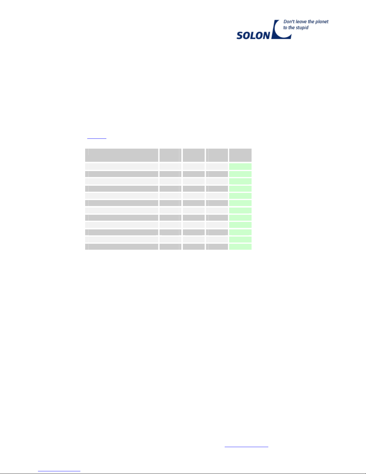
Table 1:Maximum resulting load carrying capacity of the surface
Vertical arrangement of the modules Horizontal arrangementModul type
Maximumeditionand
Connectionarea
(forexample,inlaying
System)
Optimumeditionand
connectionarea
Optimumeditionand
connectionarea
SOLONBlue230/07≤125kg/m² ≤155kg/m² ≤125kg/m²
SOLONBlack230/07(01,02)≤125kg/m² ≤155kg/m² ≤125kg/m²
SOLONBlue220/03(01,07)≤125kg/m² ≤155kg/m² ≤125kg/m²
SOLONBlack280/10≤135kg/m² ≤150kg/m² ≤135kg/m²
SOLONBlack300/10≤135kg/m² ≤150kg/m² ≤135kg/m²
SOLONP220/6+/07≤125kg/m² ≤155kg/m² ≤125kg/m²
SOLONM230/6+/07≤125kg/m²≤155kg/m²≤125kg/m²
SOLONM230/6+/01≤125kg/m²≤155kg/m²≤125kg/m²
SOLONP220/6+≤125kg/m²≤155kg/m²≤125kg/m²
SOLONM230/6+≤125kg/m²≤155kg/m²≤125kg/m²
SOLONP180/6+≤150kg/m²≤195kg/m²≤150kg/m²
SOLONP130/6+≤230kg/m²≤275kg/m²≤230kg/m²
1. Assembly of Modules on Pitched or Slanted Roofs
(assembly parallel to the roof):
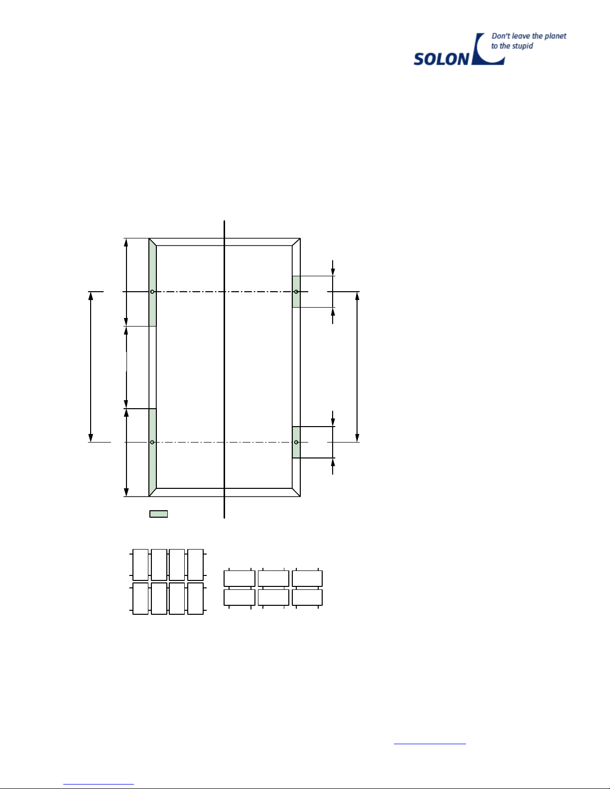
a) Vertical arrangement / assembly of the modules in the "Ms" area
>20
>20
optimal
M
s
M
s
a
min
a
Figure 1: Horizontal girder profiles
Sollbefestigungs- bzw. Sollauflagebereich
Attention!
Theframeofthemodulemustbeattachedto
therailsofthesubstructure(girderprofiles)at
fourpointsinthesameplaneinthearea
"Ms".
An attachment on the short spars is
not allowed on principle.
Slip protection:
Toprotectthemodulesfromslipping
duringtheinstallationonaninclined
plane, socketheadcapscrewsareinstalled
intheboreholesprovidedforthispurpose
(distanceaoptimal)inthelongitudinalspars.
Securingthescrewsisaccomplishedwith
toothedlockwashersandnutsorwith
self-lockingnuts.Recommended:Screw
DIN912-M6x10VAwithtoothedlock
washerDIN6797-A6,4andnutDIN555-
M6VA.
Re
q
uiredareaforattachmentandsu
pp
ort

TechnicalService
asat:08/07/2009 phone: +49 30 81879 0 fax: +49 30 81879 9999 www.solon.com 7
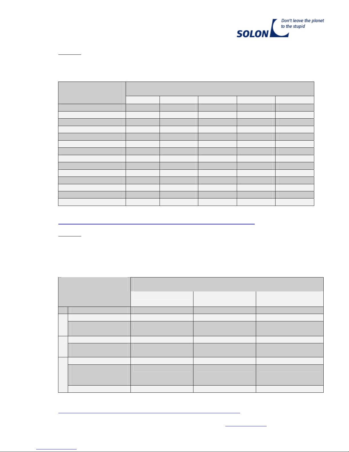
Table 2: Assembly area "MS" – vertical assembly
Standardmodule L
[mm]
B
[mm]
aoptimal
[mm]
amin
[mm]
MS
[mm]
SOLON Blue 230/07 1.640
1.000
980
510
565
SOLON Black 230/07 (01, 02) 1.640
1.000
980
510
565
SOLON Blue 220/03 (01, 07) 1.640
1.000
980
510
565
SOLON Black 280/10, 1.580
1.070
940
540
520
SOLON Black 300/10 1.580
1.070
940
540
520
SOLON P220/6+/07 1.640
1.000
980
510
565
SOLON M230/6+/07 1.640
1.000
980
510
565
SOLON M230/6+/01 1.640
1.000
980
510
565
SOLON P220/6+ 1.660
990
1.000
530
565
SOLON M230/6+ 1.660
990
1.000
530
565
SOLON P180/6+ 1.660
830
1.000
530
565
SOLON P130/6+ 1.500
680
900
470
515
b) Horizontal arrangement / assembly of the modules in the "Mw" area
M
w
M
w
a
optimal
M
w
a
optimal
M
w
Figure 2: Insertion profiles (a) Girder profiles (b) horizontal
Note!
UsageofanInsertion System
(Figure2)withsupportofthe
modulesontheouteredgeofthe
longsparsconstitutesthemost
extremestressfoeamodule,butis
approvedhoweverifthemoduleis
attachedorsupportedat4points
ofthelongsparsintherequired
area for attachment and
support.
(a)
(b)
(b)
(a)
TechnicalService
asat:08/07/2009 phone: +49 30 81879 0 fax: +49 30 81879 9999 www.solon.com 8
Figure 3: Horizontal insertion profiles Figure 4: Vertical girder profiles
Standardmodule L
[mm]
B
[mm]
aoptimal
[mm]
MW
[mm]
SOLON Blue 230/07 1.640
1.000
980
150
SOLON Black 230/07 (01, 02)
1.640
1.000
980
150
SOLON Blue 220/03 (01, 07) 1.640
1.000
980
150
SOLON Black 280/10, 1.580
1.070
940
145
SOLON Black 300/10 1.580
1.070
940
145
SOLON P220/6+/07 1.640
1.000
980
150
SOLON M230/6+/07 1.640
1.000
980
150
SOLON M230/6+/01 1.640
1.000
980
150
SOLON P220/6+ 1.660
990
1.000
150
SOLON M230/6+ 1.660
990
1.000
150
SOLON P180/6+ 1.660
830
1.000
200
SOLON P130/6+ 1.500
680
900
300
2. Assembly of Modules on Flat Roofs (installation on supports, assembly non-parallel to
the roof):
Wheninstallingmodulesonflatroofs,itisrecommendedtouseasubstructurewhichprovidesanoptimal
supportintheareaoftheslipprotectionboreholeswithoutspecialefforts.
Dependingonthetypeofassembly(horizontalorvertical),theframeofthemodulemustalwaysbe
attached(withoutdeformation)totherailsofthesubstructure(girderprofiles)atfourpointsinoneplane
intherespectivelyspecifiedinstallationarea"Mw" or "Ms".Otherwisethedetailsfrom"Assemblyof
ModulesonPitchedorSlantedRoofs"(Item1.)apply.
3. General Notes
Whenusingcommerciallyavailableassemblysystems,minimalstressforthemodulesisachievedby
optimalpositioningofthemountingrailsaswellassupportandattachmentintheareaoftheboreholes
(distanceaoptimal)!Atthis,itisalwaysassumedthatthecommerciallyavailableassemblysystemsthatare
used,whichcannotbeconsideredintheassemblyinstructions,correspondtothelateststateof
technology.Thedimensioningofthesubstructuremustberealizedinawaythatallowsdeflectionof
l/200,butnotexceedingamaximumof15mm.Makesurethattheroofconstructionitselfissuitable!
Attachmentdirectlyontheframe(usingtheslipprotectionboreholesofthelongspar)withhigh-strength
boltsM6madeofstainlesssteelwithoutpre-stressingisallowedifwasherswithadiameterofatleast14
mmareusedandtheconnectioniscarriedoutwithoutstress.
Table 3: Assembly area "MW" – horizontal assembly
Attention!
Wheninstallingmoduleshorizontally,approvalisonlygivenfortheoptimalattachmentarea"Mw",
irregardlessoftheassemblysystem.
Theframeofthemodulemustbeconnectedtotherailsofthesubstructure(girderprofiles)at
fourpointsinthearea"Mw".

TechnicalService
asat:08/07/2009 phone: +49 30 81879 0 fax: +49 30 81879 9999 www.solon.com 9
Attention! When attaching the modules, bear in mind that the material expands with
temperature changes. Therefore, we recommend a minimum distance of 20 mm between
modules.
Modules may not be allowed to stand in water. Rain and snowmelt must be allowed to drain
freely. Drainage boreholes may not be used for the assembly.
The entrance of the modules can cause irreparable damages. These damages are not secured by
the product guarantee and achievement guarantee.
Shoulditberequiredbythecircumstances,forinstanceforpersonalprotectionmeasureswhenusing
transformer-lessd.c/a.cconvertersaccordingtotheinstructionsoftheconvertermanufacturer,the
SOLONmodulesprovideapossibilitytoconnectpotentialequalizationcablesforgroundingallmetallic
componentsofanelectricalsystem(eachindividualmoduleframe)withthe4.5mmboreholesinall4
spars.
Alternativelytheslipprotectionboreholescanbeusedforthistooiftheyarenotneeded(e.g.ininsertion
systems).
Subjecttotechnicalchanges.Theassemblyinstructionsareonlyvalidincombinationwiththedata
sheets,thegeneraltermsandconditionsandthewarrantyandperformanceguaranteesoftheSOLONPV
GmbHandSOLONNordGmbHintheirrespectivelyvalidversion.SOLONdoesnotassumeliabilityfor
theseassemblyinstructionsandpossibleconsequentialdamage,withtheexceptionoftheliability
regardingproductliabilitylawandtheliabilityresultingfromdeliberateactsandgrossnegligence.
Detailed calculation results of the allowable snow loads skallow for the modules SOLON BLUE
230/07, SOLON BLACK 230/07 (01, 02), SOLON Blue 220/03 (01,07),
SOLON P220/6+/07, SOLON M230/6+/07, SOLON M230/6+/01, SOLON P220/6+,
SOLON P180/6+ und SOLON P130/6+are described in the Annexes 3 through 6 for the following
assembly variants:
1. Vertical assembly of the modules
Maximumattachmentandsupportarea(pitchedroof) (Annexes3-6,sheets1.1and1.2)
Maximumattachmentandsupportarea(flatroof) (Annexes3-6,sheets2.1and2.2)
Optimumattachmentandsupportarea(pitchedroof) (Annexes3-6,sheets3.1and3.2)
Optimumattachmentandsupportarea(flatroof) (Annexes3-6,sheets4.1and4.2)
2. Horizontal assembly of the modules
Onlyoptimumattachmentandsupportarea(pitchedroof) (Annexes3-6,sheets5.1and5.2)
Onlyoptimumattachmentandsupportarea(flatroof) (Annexes3-6,sheets6.1and6.2)
Incaseofquestionsorlackofclarity,thespecialistfirmscarryingouttheassemblycandirectlyreferto
theircontractualpartneroranaccreditedstructuralengineer.SOLONcannametherespectiveexperts
uponrequest.Pleasealsousethechecklist"Technical Dimensioning Guide for the Assembly of
SOLON Modules"forthis.Youcanfinddetailsforthisonourhomepage(www.solonag.com).
TechnicalService
asat:08/07/2009 phone: +49 30 81879 0 fax: +49 30 81879 9999 www.solon.com 10
ABSTRACT OF THE ASSEMBLY INSTRUCTIONS FOR SOLON STANDARD MODULES
Approvaloftheassemblymethodsshownhereisonlygivenuptothespecifiedresultingloadcarrying
capacityofthesurfaceinkNperm²ofmodulesurface,whichcanbefoundintheassemblyinstructions
fortherespectivemodule(Table1).Thisisthebasisforthecalculationoftheallowablesnowloadonthe
groundskallow(Annexes3through6oftheAssemblyinstructions).Allresultsconformtothecurrentlyvalid
standardsandregulations(e.g.windloadaccordingtoDIN1055-Part4(03/2005)andsnowload
accordingtoDIN1055-Part5(07/2005)).
1. Vertical Assembly 2. Horizontal Assembly
Horizontal girder profiles Vertical girder profiles
Theframeofthemodulemustbeconnectedwithoutdeformationatfourpointsintheareas"Ms"and
"Mw",respectively,totherailsofthesubstructure(girderprofiles).Anattachmenttotheshortsparsis
notallowedonprinciple.
M
w
M
w
a
optimal
a
min
M
s
M
s
Required area for attachment and support
a optimal

TechnicalService
asat:08/07/2009 phone: +49 30 81879 0 fax: +49 30 81879 9999 www.solon.com 11
StandardmoduleL
[mm]
B
[mm]
aoptimal
[mm]
amin
[mm]
MS
[mm]
MW
[mm]
SOLON Blue 230/07 1.640
1.000
980
510
565
150
SOLON Black 230/07 (01, 02) 1.640
1.000
980
510
565
150
SOLON Blue 220/03 (01, 07) 1.640
1.000
980
510
565
150
SOLON Black 280/10 1.580
1.070
940
540
520
145
SOLON Black 300/10 1.580
1.070
940
540
520
145
SOLON P220/6+/07 1.640
1.000
980
510
565
150
SOLON M230/6+/07 1.640
1.000
980
510
565
150
SOLON M230/6+/01 1.640
1.000
980
510
565
150
SOLON P220/6+ 1.660
990
1.000
530
565
150
SOLON M230/6+ 1.660
990
1.000
530
565
150
SOLON P180/6+ 1.660
830
1.000
530
565
200
SOLON P130/6+ 1.500
680
900
470
515
300
Follow please the detailed
assembly tips under
www.solon.com
SOLON SE
Am Studio 16
12489 Berlin
phone.: 030 81879 0
fax: 030 81879 9999
TechnicalService
asat:08/07/2009 phone: +49 30 81879 0 fax: +49 30 81879 9999 www.solon.com 12
Annex 1
Snow load on the ground skin kN/m² according to DIN 1055 (Part 5) depending on the snow
load zone and the ground level elevation of the location of the building above sea level (m)
Snow load zone
sk(kN/m²)
Ground elevation of
the building site
above sea level (m) 1 1a 2 2a 3
<200 0.65 0.81 0.85 1.06 1.10
300 0.65 0.81 0.89 1.11 1.29
400 0.65 0.81 1.21 1.51 1.78
500 0.84 1.05 1.60 2.00 2.38
600 1.05 1.30 2.06 2.58 3.08
700 1.30 1.59 2.58 3.24 3.86
800 1.59 1.99 3.17 3.97 4.76
900 - - 3.82 4.79 5.76
1000 - - 4.55 5.69 6.86
1100 - - 5.34 6.68 8.06
1200 - - 6.19 7.74 9.36
1300 - - - - 10.76
1400 - - - - 12.26
1500 - - - - 13.88
Note:DeterminationofthesnowloadzoneforsitesinGermanyispossibleat:
www.dibt.de/de/Data/Schneelastzonen_nach_Verwaltungsgrenzen.xls
Annex 2
Speed pressure q in kN/m² according to DIN 1055 (Part 4) depending on the wind zone and
the location of the site as well as the height of the building h (simplified procedure for
building heights up to 25 m. On islands in the North Sea, this table applies only for
buildings up to 10 m)
Speed pressure q in kN/m²
for building heights h within the limits of …..
Wind zone and
location of site
up to 10 m above 10 m up to 18
m
above 18 m up to 25
m
1 inland0.50 0.65 0.75
inland0.65 0.80 0.902
BalticSeacoast/
islands
0.85 1.00 1.10
inland0.80 0.95 1.103
BalticSeacoast/
islands
1.05 1.20 1.30
inland 0.95 1.15 1.30
NorthSeacoast
BalticSeacoast/
islands
1.25 1.40 1.55
4
NorthSeaislands1.40 - -
Note:DeterminationofthewindzoneforsitesinGermanyispossibleat:
www.dibt.de/de/Data/Windzonen_nach_Verwaltungsgrenzen.xls

TechnicalService
asat:08/07/2009 phone: +49 30 81879 0 fax: +49 30 81879 9999 www.solon.com 13
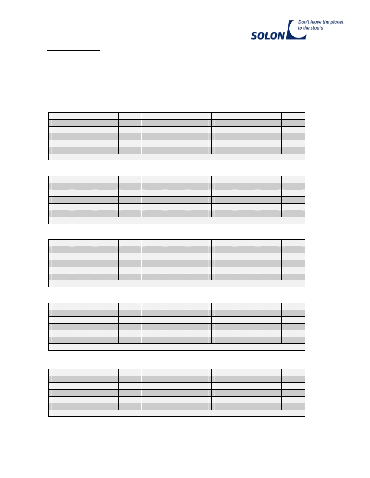
Annex 3 Sheet 1.1
SOLON Blue 230/07, SOLON Black 230/07 (01, 02), SOLON Blue 220/03 (01, 07),
SOLON P220/6+/07 (Vertical Assembly / Pitched Roof or Slanted Roof)
AllowablesnowloadsonthegroundskallowinkN/m²accordingtoDIN1055-5(Version07.2005)
dependingonthepitchoftheroofandthemoduleandthespeedpressureqinkN/m²
Maximumsupportandattachmentarea
Speed pressure q = 0.65 kN/m²
α= β0° 1° 2° 3° 4° 5° 6° 7° 8° 9°
10° 1.42 1.43 1.44 1.46 1.47 1.48 1.49 1.50 1.51 1.52
20° 1.54 1.55 1.57 1.58 1.60 1.62 1.64 1.66 1.69 1.71
30° 1.74 1.83 1.93 2.04 2.16 2.29 2.44 2.60 2.78 2.99
40° 3.22 3.48 3.77 4.11 4.50 4.95 5.50 6.12 6.90 7.83
50° 8.94 10.37 12.20 14.54 17.81 22.49 29.39 41.43 66.03 137.18
60° No calculative consideration of the snow load, usable in all snow load zones.
Speed pressure q = 0.75 kN/m²
α= β0° 1° 2° 3° 4° 5° 6° 7° 8° 9°
10° 1.41 1.42 1.43 1.44 1.45 1.47 1.47 1.48 1.49 1.50
20° 1.51 1.53 1.54 1.55 1.57 1.59 1.61 1.63 1.65 1.67
30° 1.70 1.79 1.88 1.99 2.10 2.23 2.37 2.53 2.70 2.90
40° 3.12 3.36 3.65 3.97 4.34 4.77 5.29 5.90 6.64 7.53
50° 8.60 9.97 11.72 13.96 17.09 21.57 28.19 39.71 63.26 131.37
60° No calculative consideration of the snow load, usable in all snow load zones.
Speed pressure q = 0.85 kN/m²
α= β0° 1° 2° 3° 4° 5° 6° 7° 8° 9°
10° 1.39 1.40 1.41 1.42 1.44 1.45 1.46 1.46 1.47 1.48
20° 1.49 1.50 1.51 1.53 1.54 1.56 1.58 1.59 1.62 1.64
30° 1.66 1.74 1.83 1.93 2.05 2.17 2.30 2.45 2.62 2.80
40° 3.02 3.25 3.52 3.83 4.18 4.59 5.09 5.67 6.38 7.23
50° 8.25 9.57 11.24 13.39 16.37 20.66 26.98 37.99 60.50 125.56
60° No calculative consideration of the snow load, usable in all snow load zones.
Speed pressure q = 0.95 kN/m²
α= β0° 1° 2° 3° 4° 5° 6° 7° 8° 9°
10° 1.38 1.39 1.40 1.41 1.42 1.44 1.44 1.45 1.45 1.46
20° 1.47 1.48 1.49 1.50 1.51 1.53 1.54 1.56 1.58 1.60
30° 1.62 1.70 1.79 1.88 1.99 2.10 2.23 2.38 2.53 2.71
40° 2.91 3.13 3.39 3.69 4.02 4.41 4.89 5.44 6.12 6.93
50° 7.91 9.16 10.76 12.81 15.66 19.74 25.77 36.28 57.73 119.75
60° No calculative consideration of the snow load, usable in all snow load zones.
Speed pressure q = 1.00 kN/m²
α= β0° 1° 2° 3° 4° 5° 6° 7° 8° 9°
10° 1.37 1.38 1.39 1.40 1.41 1.43 1.43 1.44 1.44 1.45
20° 1.46 1.47 1.48 1.49 1.50 1.51 1.53 1.54 1.56 1.58
30° 1.60 1.68 1.76 1.86 1.96 2.07 2.20 2.34 2.49 2.67
40° 2.86 3.08 3.33 3.62 3.94 4.32 4.79 5.33 5.99 6.78
50° 7.74 8.96 10.52 12.52 15.30 19.29 25.17 35.42 56.34 116.85
60° No calculative consideration of the snow load, usable in all snow load zones.
SOLON BLUE 230/07, SOLON BLACK 230/07 (01, 02), SOLON Blue 220/03 (01,07), SOLON P220/6+/07,
SOLON M230/6+/07 (01) are structurally identical.

TechnicalService
asat:08/07/2009 phone: +49 30 81879 0 fax: +49 30 81879 9999 www.solon.com 14
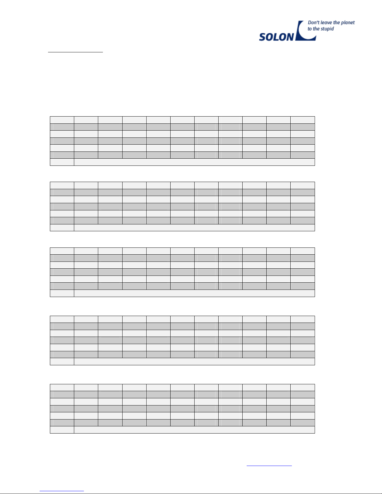
Annex 3 Sheet 1.2
SOLON Blue 230/07, SOLON Black 230/07 (01, 02), SOLON Blue 220/03 (01, 07),
SOLON P220/6+/07 (Vertical Assembly / Pitched Roof or Slanted Roof)
AllowablesnowloadsonthegroundskallowinkN/m²accordingtoDIN1055-5(Version07.2005)
dependingonthepitchoftheroofandthemoduleandthespeedpressureqinkN/m²
Maximumsupportandattachmentarea
Speed pressure q = 1.05 kN/m²
α= β0° 1° 2° 3° 4° 5° 6° 7° 8° 9°
10° 1.36 1.37 1.38 1.39 1.41 1.42 1.42 1.43 1.43 1.44
20° 1.45 1.45 1.46 1.47 1.49 1.50 1.51 1.53 1.54 1.56
30° 1.58 1.66 1.74 1.83 1.93 2.04 2.16 2.30 2.45 2.62
40° 2.81 3.02 3.27 3.55 3.86 4.23 4.69 5.21 5.86 6.63
50° 7.57 8.76 10.28 12.23 14.94 18.83 24.57 34.56 54.96 113.95
60° No calculative consideration of the snow load, usable in all snow load zones.
Speed pressure q = 1.15 kN/m²
α= β0° 1° 2° 3° 4° 5° 6° 7° 8° 9°
10° 1.35 1.36 1.37 1.38 1.39 1.40 1.40 1.41 1.41 1.42
20° 1.42 1.43 1.44 1.45 1.46 1.47 1.48 1.49 1.51 1.52
30° 1.54 1.61 1.69 1.78 1.87 1.98 2.09 2.22 2.37 2.53
40° 2.71 2.91 3.14 3.40 3.70 4.05 4.48 4.98 5.60 6.34
50° 7.22 8.35 9.80 11.65 14.23 17.91 23.36 32.84 52.19 108.14
60° No calculative consideration of the snow load, usable in all snow load zones.
Speed pressure q = 1.25 kN/m²
α= β0° 1° 2° 3° 4° 5° 6° 7° 8° 9°
10° 1.33 1.34 1.35 1.36 1.37 1.39 1.39 1.39 1.39 1.40
20° 1.40 1.41 1.41 1.42 1.43 1.44 1.45 1.46 1.47 1.49
30° 1.50 1.57 1.64 1.73 1.82 1.91 2.03 2.15 2.28 2.43
40° 2.61 2.79 3.01 3.26 3.54 3.87 4.28 4.76 5.34 6.04
50° 6.88 7.95 9.32 11.07 13.51 17.00 22.15 31.12 49.42 102.33
60° No calculative consideration of the snow load, usable in all snow load zones.
Speed pressure q = 1.30 kN/m²
α= β0° 1° 2° 3° 4° 5° 6° 7° 8° 9°
10° 1.32 1.33 1.34 1.35 1.37 1.38 1.38 1.38 1.38 1.39
20° 1.39 1.39 1.40 1.41 1.41 1.42 1.43 1.44 1.45 1.47
30° 1.48 1.55 1.62 1.70 1.79 1.88 1.99 2.11 2.24 2.39
40° 2.56 2.74 2.95 3.19 3.46 3.78 4.18 4.64 5.21 5.89
50° 6.70 7.75 9.08 10.78 13.15 16.54 21.55 30.26 48.04 99.42
60° No calculative consideration of the snow load, usable in all snow load zones.
Speed pressure q = 1.40 kN/m²
α= β0° 1° 2° 3° 4° 5° 6° 7° 8° 9°
10° 1.31 1.32 1.33 1.34 1.35 1.36 1.36 1.36 1.36 1.36
20° 1.37 1.37 1.37 1.38 1.38 1.39 1.40 1.41 1.42 1.43
30° 1.44 1.50 1.57 1.65 1.73 1.82 1.92 2.04 2.16 2.30
40° 2.45 2.62 2.82 3.05 3.30 3.60 3.98 4.41 4.95 5.59
50° 6.36 7.34 8.60 10.20 12.44 15.63 20.34 28.54 45.27 93.61
60° No calculative consideration of the snow load, usable in all snow load zones.
SOLON Blue 230/07, SOLON Black 230/07 (01, 02), SOLON Blue 220/03 (01, 07), SOLON P220/6+/07,
SOLON M230/6+/07 (01) are structurally identical.
Annex 3 Sheet 2.1

TechnicalService
asat:08/07/2009 phone: +49 30 81879 0 fax: +49 30 81879 9999 www.solon.com 15
SOLON Blue 230/07, SOLON Black 230/07 (01, 02), SOLON Blue 220/03 (01, 07),
SOLON P220/6+/07 (Vertical Assembly / Flat Roof)
AllowablesnowloadsonthegroundskallowinkN/m²accordingtoDIN1055-5(Version07.2005)
dependingonthepitchofthemoduleandthespeedpressureqinkN/m²
Maximumsupportandattachmentarea
Speed pressure q = 0.65 kN/m²
β0° 1° 2° 3° 4° 5° 6° 7° 8° 9°
10° 1.12 1.13 1.14 1.15 1.16 1.17 1.17 1.18 1.19 1.20
20° 1.20 1.21 1.23 1.24 1.25 1.26 1.28 1.29 1.31 1.33
30° 1.35 1.42 1.49 1.58 1.67 1.77 1.88 2.00 2.14 2.30
40° 2.47 2.67 2.89 3.15 3.44 3.78 4.20 4.67 5.26 5.97
50° 6.82 7.91 9.31 11.09 13.57 17.14 22.40 31.57 50.31 104.50
60° No calculative consideration of the snow load, usable in all snow load zones.
Speed pressure q = 0.75 kN/m²
β0° 1° 2° 3° 4° 5° 6° 7° 8° 9°
10° 1.06 1.07 1.08 1.08 1.09 1.11 1.11 1.11 1.12 1.12
20° 1.13 1.14 1.15 1.16 1.17 1.18 1.19 1.20 1.22 1.23
30° 1.25 1.31 1.38 1.45 1.54 1.62 1.73 1.84 1.96 2.10
40° 2.25 2.43 2.63 2.86 3.11 3.42 3.79 4.22 4.75 5.39
50° 6.15 7.13 8.38 9.98 12.21 15.40 20.12 28.34 45.12 93.67
60° No calculative consideration of the snow load, usable in all snow load zones.
Speed pressure q = 0.85 kN/m²
β0° 1° 2° 3° 4° 5° 6° 7° 8° 9°
10° 1.00 1.01 1.01 1.02 1.03 1.04 1.04 1.05 1.05 1.05
20° 1.06 1.06 1.07 1.08 1.08 1.09 1.10 1.11 1.12 1.14
30° 1.15 1.21 1.26 1.33 1.40 1.48 1.57 1.67 1.78 1.90
40° 2.04 2.19 2.37 2.57 2.79 3.06 3.39 3.77 4.24 4.80
50° 5.48 6.35 7.45 8.87 10.84 13.66 17.83 25.10 39.93 82.83
60° No calculative consideration of the snow load, usable in all snow load zones.
Speed pressure q = 0.95 kN/m²
β0° 1° 2° 3° 4° 5° 6° 7° 8° 9°
10° 0.94 0.94 0.95 0.96 0.97 0.98 0.98 0.98 0.98 0.98
20° 0.98 0.99 0.99 1.00 1.00 1.01 1.01 1.02 1.03 1.04
30° 1.05 1.10 1.15 1.21 1.27 1.34 1.42 1.50 1.59 1.70
40° 1.82 1.95 2.10 2.28 2.47 2.70 2.99 3.32 3.73 4.22
50° 4.81 5.56 6.53 7.76 9.47 11.93 15.55 21.86 34.75 72.00
60° No calculative consideration of the snow load, usable in all snow load zones.
Speed pressure q = 1.00 kN/m²
β0° 1° 2° 3° 4° 5° 6° 7° 8° 9°
10° 0.91 0.91 0.92 0.93 0.94 0.94 0.94 0.94 0.94 0.95
20° 0.95 0.95 0.95 0.96 0.96 0.96 0.97 0.98 0.98 0.99
30° 1.00 1.04 1.09 1.15 1.20 1.27 1.34 1.42 1.50 1.60
40° 1.71 1.83 1.97 2.13 2.31 2.52 2.79 3.10 3.47 3.93
50° 4.47 5.17 6.06 7.20 8.79 11.06 14.41 20.24 32.15 66.58
60° No calculative consideration of the snow load, usable in all snow load zones.
SOLON Blue 230/07, SOLON Black 230/07 (01, 02), SOLON Blue 220/03 (01, 07), SOLON P220/6+/07,
SOLON M230/6+/07 (01) are structurally identical.

TechnicalService
asat:08/07/2009 phone: +49 30 81879 0 fax: +49 30 81879 9999 www.solon.com 16
Annex 3 Sheet 2.2
SOLON Blue 230/07, SOLON Black 230/07 (01, 02), SOLON Blue 220/03 (01, 07),
SOLON P220/6+/07 (Vertical Assembly / Flat Roof)
AllowablesnowloadsonthegroundskallowinkN/m²accordingtoDIN1055-5(Version07.2005)
dependingonthepitchofthemoduleandthespeedpressureqinkN/m²
Maximumsupportandattachmentarea
Speed pressure q = 1.05 kN/m²
β0° 1° 2° 3° 4° 5° 6° 7° 8° 9°
10° 0.87 0.88 0.89 0.90 0.90 0.91 0.91 0.91 0.91 0.91
20° 0.91 0.91 0.91 0.92 0.92 0.92 0.93 0.93 0.94 0.94
30° 0.95 0.99 1.04 1.08 1.14 1.20 1.26 1.33 1.41 1.50
40° 1.60 1.71 1.84 1.99 2.15 2.34 2.59 2.87 3.22 3.64
50° 4.14 4.78 5.60 6.65 8.10 10.19 13.27 18.62 29.56 61.16
60° No calculative consideration of the snow load, usable in all snow load zones.
Speed pressure q = 1.15 kN/m²
β0° 1° 2° 3° 4° 5° 6° 7° 8° 9°
10° 0.81 0.82 0.82 0.83 0.84 0.85 0.84 0.84 0.84 0.84
20° 0.84 0.84 0.84 0.84 0.84 0.84 0.84 0.84 0.84 0.85
30° 0.85 0.88 0.92 0.96 1.01 1.05 1.11 1.17 1.23 1.30
40° 1.38 1.47 1.58 1.69 1.83 1.98 2.18 2.42 2.71 3.05
50° 3.47 4.00 4.67 5.54 6.74 8.45 10.98 15.39 24.37 50.32
60° No calculative consideration of the snow load, usable in all snow load zones.
Speed pressure q = 1.25 kN/m²
β0° 1° 2° 3° 4° 5° 6° 7° 8° 9°
10° 0.75 0.76 0.76 0.77 0.78 0.78 0.78 0.77 0.77 0.77
20° 0.76 0.76 0.76 0.76 0.75 0.75 0.75 0.75 0.75 0.75
30° 0.75 0.78 0.81 0.84 0.87 0.91 0.95 1.00 1.05 1.10
40° 1.17 1.24 1.31 1.40 1.50 1.62 1.78 1.97 2.20 2.47
50° 2.80 3.22 3.75 4.43 5.37 6.72 8.70 12.15 19.18 39.49
60° No calculative consideration of the snow load, usable in all snow load zones.
Speed pressure q = 1.30 kN/m²
β0° 1° 2° 3° 4° 5° 6° 7° 8° 9°
10° 0.72 0.72 0.73 0.74 0.74 0.75 0.75 0.74 0.74 0.73
20° 0.73 0.72 0.72 0.72 0.71 0.71 0.71 0.70 0.70 0.70
30° 0.70 0.72 0.75 0.78 0.81 0.84 0.87 0.91 0.96 1.00
40° 1.06 1.12 1.18 1.26 1.34 1.44 1.58 1.74 1.94 2.18
50° 2.46 2.82 3.28 3.87 4.69 5.85 7.56 10.53 16.59 34.07
60° No calculative consideration of the snow load, usable in all snow load zones.
Speed pressure q = 1.40 kN/m²
β0° 1° 2° 3° 4° 5° 6° 7° 8° 9°
10° 0.66 0.66 0.67 0.67 0.68 0.69 0.68 0.67 0.67 0.66
20° 0.65 0.65 0.64 0.63 0.63 0.62 0.62 0.61 0.61 0.60
30° 0.60 0.62 0.63 0.65 0.67 0.69 0.72 0.75 0.77 0.81
40° 0.84 0.88 0.92 0.97 1.02 1.08 1.18 1.29 1.43 1.59
50° 1.79 2.04 2.36 2.76 3.32 4.11 5.28 7.30 11.40 23.23
60° No calculative consideration of the snow load, usable in all snow load zones.
SOLON Blue 230/07, SOLON Black 230/07 (01, 02), SOLON Blue 220/03 (01, 07),SOLON P220/6+/07,
SOLON M230/6+/07 (01) are structurally identical
TechnicalService
asat:08/07/2009 phone: +49 30 81879 0 fax: +49 30 81879 9999 www.solon.com 17
Annex 3 Sheet 3.1
SOLON Blue 230/07, SOLON Black 230/07 (01, 02), SOLON Blue 220/03 (01, 07),
SOLON P220/6+/07 (Vertical Assembly / Pitched Roof or Slanted Roof)
AllowablesnowloadsonthegroundskallowinkN/m²accordingtoDIN1055-5(Version07.2005)
dependingonthepitchoftheroofandthemoduleandthespeedpressureqinkN/m²
Maximumloadcapacity–Optimumsupportandattachmentarea
Speed pressure q = 0.65 kN/m²
α= β0° 1° 2° 3° 4° 5° 6° 7° 8° 9°
10° 1.71 1.72 1.73 1.75 1.76 1.78 1.79 1.80 1.82 1.83
20° 1.85 1.87 1.89 1.91 1.93 1.95 1.98 2.01 2.04 2.07
30° 2.11 2.22 2.34 2.47 2.62 2.78 2.96 3.17 3.39 3.64
40° 3.92 4.24 4.60 5.02 5.49 6.05 6.72 7.49 8.43 9.57
50° 10.94 12.69 14.93 17.79 21.79 27.51 35.97 50.71 80.82 167.90
60° No calculative consideration of the snow load, usable in all snow load zones.
Speed pressure q = 0.75 kN/m²
α= β0° 1° 2° 3° 4° 5° 6° 7° 8° 9°
10° 1.69 1.70 1.72 1.73 1.75 1.76 1.77 1.78 1.80 1.81
20° 1.82 1.84 1.86 1.88 1.90 1.92 1.95 1.98 2.00 2.03
30° 2.07 2.18 2.29 2.42 2.57 2.72 2.90 3.09 3.30 3.55
40° 3.82 4.12 4.48 4.88 5.33 5.87 6.51 7.26 8.17 9.27
50° 10.59 12.28 14.45 17.21 21.07 26.60 34.76 48.99 78.05 162.09
60° No calculative consideration of the snow load, usable in all snow load zones.
Speed pressure q = 0.85 kN/m²
α= β0° 1° 2° 3° 4° 5° 6° 7° 8° 9°
10° 1.68 1.69 1.70 1.71 1.73 1.75 1.75 1.76 1.78 1.79
20° 1.80 1.82 1.83 1.85 1.87 1.89 1.92 1.94 1.97 2.00
30° 2.03 2.13 2.24 2.37 2.51 2.66 2.83 3.01 3.22 3.45
40° 3.72 4.01 4.35 4.74 5.17 5.69 6.31 7.03 7.91 8.97
50° 10.25 11.88 13.97 16.63 20.35 25.68 33.56 47.27 75.28 156.28
60° No calculative consideration of the snow load, usable in all snow load zones.
Speed pressure q = 0.95 kN/m²
α= β0° 1° 2° 3° 4° 5° 6° 7° 8° 9°
10° 1.66 1.67 1.68 1.70 1.71 1.73 1.74 1.75 1.76 1.77
20° 1.78 1.79 1.81 1.83 1.84 1.86 1.88 1.91 1.93 1.96
30° 1.99 2.09 2.20 2.32 2.45 2.59 2.76 2.94 3.14 3.36
40° 3.62 3.90 4.22 4.60 5.01 5.51 6.11 6.80 7.65 8.68
50° 9.90 11.48 13.49 16.06 19.64 24.77 32.35 45.55 72.51 150.48
60° No calculative consideration of the snow load, usable in all snow load zones.
Speed pressure q = 1.00 kN/m²
α= β0° 1° 2° 3° 4° 5° 6° 7° 8° 9°
10° 1.65 1.66 1.68 1.69 1.71 1.72 1.73 1.74 1.75 1.76
20° 1.77 1.78 1.80 1.81 1.83 1.85 1.87 1.89 1.91 1.94
30° 1.97 2.07 2.17 2.29 2.42 2.56 2.72 2.90 3.09 3.32
40° 3.57 3.84 4.16 4.52 4.93 5.42 6.01 6.69 7.52 8.53
50° 9.73 11.27 13.25 15.77 19.28 24.31 31.74 44.69 71.13 147.57
60° No calculative consideration of the snow load, usable in all snow load zones.
SOLON Blue 230/07, SOLON Black 230/07 (01, 02), SOLON Blue 220/03 (01, 07), SOLON P220/6+/07,
SOLON M230/6+/07 (01) are structurally identical.

TechnicalService
asat:08/07/2009 phone: +49 30 81879 0 fax: +49 30 81879 9999 www.solon.com 18
Annex 3 Sheet 3.2
SOLON Blue 230/07, SOLON Black 230/07 (01, 02), SOLON Blue 220/03 (01, 07),
SOLON P220/6+/07 (Vertical Assembly / Pitched Roof or Slanted Roof)
AllowablesnowloadsonthegroundskallowinkN/m²accordingtoDIN1055-5(Version07.2005)
dependingonthepitchoftheroofandthemoduleandthespeedpressureqinkN/m²
Maximumloadcapacity-Optimumsupportandattachmentarea
Speed pressure q = 1.05 kN/m²
α= β0° 1° 2° 3° 4° 5° 6° 7° 8° 9°
10° 1.64 1.66 1.67 1.68 1.70 1.71 1.72 1.73 1.74 1.75
20° 1.76 1.77 1.78 1.80 1.81 1.83 1.85 1.87 1.90 1.92
30° 1.95 2.04 2.15 2.26 2.39 2.53 2.69 2.86 3.05 3.27
40° 3.51 3.78 4.10 4.45 4.85 5.33 5.91 6.58 7.39 8.38
50° 9.56 11.07 13.01 15.48 18.92 23.86 31.14 43.83 69.74 144.67
60° No calculative consideration of the snow load, usable in all snow load zones.
Speed pressure q = 1.15 kN/m²
α= β0° 1° 2° 3° 4° 5° 6° 7° 8° 9°
10° 1.63 1.64 1.65 1.67 1.68 1.70 1.70 1.71 1.72 1.72
20° 1.73 1.74 1.76 1.77 1.79 1.80 1.82 1.84 1.86 1.88
30° 1.91 2.00 2.10 2.21 2.34 2.47 2.62 2.79 2.97 3.18
40° 3.41 3.67 3.97 4.31 4.70 5.15 5.71 6.35 7.13 8.08
50° 9.21 10.67 12.53 14.90 18.21 22.94 29.93 42.11 66.97 138.86
60° No calculative consideration of the snow load, usable in all snow load zones.
Speed pressure q = 1.25 kN/m²
α= β0° 1° 2° 3° 4° 5° 6° 7° 8° 9°
10° 1.61 1.63 1.64 1.65 1.67 1.68 1.69 1.69 1.70 1.70
20° 1.71 1.72 1.73 1.74 1.76 1.77 1.79 1.80 1.82 1.84
30° 1.87 1.96 2.05 2.16 2.28 2.41 2.55 2.71 2.89 3.09
40° 3.31 3.56 3.84 4.17 4.54 4.97 5.50 6.12 6.87 7.78
50° 8.87 10.26 12.05 14.32 17.49 22.03 28.73 40.39 64.20 133.05
60° No calculative consideration of the snow load, usable in all snow load zones.
Speed pressure q = 1.30 kN/m²
α= β0° 1° 2° 3° 4° 5° 6° 7° 8° 9°
10° 1.61 1.62 1.63 1.64 1.66 1.67 1.68 1.68 1.69 1.69
20° 1.70 1.71 1.72 1.73 1.74 1.76 1.77 1.79 1.81 1.83
30° 1.85 1.93 2.03 2.13 2.25 2.38 2.52 2.67 2.84 3.04
40° 3.26 3.50 3.78 4.10 4.46 4.88 5.40 6.01 6.74 7.63
50° 8.70 10.06 11.81 14.03 17.13 21.57 28.12 39.53 62.82 130.14
60° No calculative consideration of the snow load, usable in all snow load zones.
Speed pressure q = 1.40 kN/m²
α= β0° 1° 2° 3° 4° 5° 6° 7° 8° 9°
10° 1.59 1.60 1.61 1.63 1.64 1.66 1.66 1.66 1.67 1.67
20° 1.68 1.68 1.69 1.70 1.71 1.73 1.74 1.75 1.77 1.79
30° 1.81 1.89 1.98 2.08 2.19 2.31 2.45 2.60 2.76 2.95
40° 3.16 3.39 3.65 3.96 4.30 4.70 5.20 5.78 6.48 7.34
50° 8.35 9.66 11.32 13.45 16.41 20.66 26.91 37.81 60.05 124.34
60° No calculative consideration of the snow load, usable in all snow load zones.
SOLON Blue 230/07, SOLON Black 230/07 (01, 02), SOLON Blue 220/03 (01, 07), SOLON P220/6+/07,
SOLON M230/6+/07 (01) are structurally identical.

TechnicalService
asat:08/07/2009 phone: +49 30 81879 0 fax: +49 30 81879 9999 www.solon.com 19
Annex 3 Sheet 4.1
SOLON Blue 230/07, SOLON Black 230/07 (01, 02), SOLON Blue 220/03 (01, 07),
SOLON P220/6+/07 (Vertical Assembly / Flat Roof)
AllowablesnowloadsonthegroundskallowinkN/m²accordingtoDIN1055-5(Version07.2005)
dependingonthepitchofthemoduleandthespeedpressureqinkN/m²
Maximumloadcapacity-Optimumsupportandattachmentarea
Speed pressure q = 0.65 kN/m²
β0° 1° 2° 3° 4° 5° 6° 7° 8° 9°
10° 1.41 1.42 1.43 1.44 1.45 1.46 1.47 1.48 1.49 1.50
20° 1.52 1.53 1.54 1.56 1.58 1.60 1.62 1.64 1.66 1.69
30° 1.72 1.81 1.90 2.01 2.13 2.26 2.41 2.57 2.74 2.95
40° 3.18 3.43 3.72 4.06 4.43 4.88 5.42 6.04 6.80 7.72
50° 8.82 10.23 12.03 14.34 17.55 22.17 28.98 40.84 65.09 135.23
60° No calculative consideration of the snow load, usable in all snow load zones.
Speed pressure q = 0.75 kN/m²
β0° 1° 2° 3° 4° 5° 6° 7° 8° 9°
10° 1.34 1.35 1.36 1.37 1.39 1.40 1.41 1.41 1.42 1.43
20° 1.44 1.45 1.47 1.48 1.50 1.51 1.53 1.55 1.57 1.59
30° 1.62 1.70 1.79 1.89 2.00 2.12 2.25 2.40 2.56 2.75
40° 2.96 3.19 3.46 3.76 4.11 4.52 5.02 5.59 6.29 7.13
50° 8.15 9.44 11.10 13.23 16.19 20.43 26.69 37.61 59.90 124.39
60° No calculative consideration of the snow load, usable in all snow load zones.
Speed pressure q = 0.85 kN/m²
β0° 1° 2° 3° 4° 5° 6° 7° 8° 9°
10° 1.28 1.29 1.30 1.31 1.32 1.34 1.34 1.35 1.35 1.36
20° 1.37 1.38 1.39 1.40 1.41 1.43 1.44 1.46 1.48 1.50
30° 1.52 1.59 1.67 1.76 1.87 1.97 2.10 2.23 2.38 2.55
40° 2.74 2.95 3.20 3.47 3.79 4.16 4.61 5.14 5.78 6.55
50° 7.47 8.66 10.18 12.12 14.82 18.69 24.41 34.37 54.72 113.55
60° No calculative consideration of the snow load, usable in all snow load zones.
Speed pressure q = 0.95 kN/m²
β0° 1° 2° 3° 4° 5° 6° 7° 8° 9°
10° 1.22 1.23 1.24 1.25 1.26 1.27 1.27 1.28 1.28 1.29
20° 1.30 1.30 1.31 1.32 1.33 1.34 1.35 1.37 1.38 1.40
30° 1.42 1.49 1.56 1.64 1.73 1.83 1.94 2.06 2.20 2.35
40° 2.52 2.71 2.93 3.18 3.47 3.80 4.21 4.68 5.26 5.97
50° 6.80 7.88 9.25 11.01 13.45 16.96 22.13 31.13 49.53 102.72
60° No calculative consideration of the snow load, usable in all snow load zones.
Speed pressure q = 1.00 kN/m²
β0° 1° 2° 3° 4° 5° 6° 7° 8° 9°
10° 1.19 1.20 1.21 1.22 1.23 1.24 1.24 1.24 1.25 1.25
20° 1.26 1.26 1.27 1.28 1.29 1.30 1.31 1.32 1.34 1.35
30° 1.37 1.43 1.50 1.58 1.67 1.76 1.86 1.98 2.11 2.25
40° 2.41 2.59 2.80 3.04 3.30 3.62 4.01 4.46 5.01 5.67
50° 6.47 7.49 8.79 10.45 12.77 16.09 20.98 29.52 46.94 97.30
60° No calculative consideration of the snow load, usable in all snow load zones.
SOLON Blue 230/07, SOLON Black 230/07 (01, 02), SOLON Blue 220/03 (01, 07), SOLON P220/6+/07,
SOLON M230/6+/07 (01) are structurally identical.
TechnicalService
asat:08/07/2009 phone: +49 30 81879 0 fax: +49 30 81879 9999 www.solon.com 20
Annex 3 Sheet 4.2
SOLON Blue 230/07, SOLON Black 230/07 (01, 02), SOLON Blue 220/03 (01, 07),
SOLON P220/6+/07 (Vertical Assembly / Flat Roof)
AllowablesnowloadsonthegroundskallowinkN/m²accordingtoDIN1055-5(Version07.2005)
dependingonthepitchofthemoduleandthespeedpressureqinkN/m²
Maximumloadcapacity-Optimumsupportandattachmentarea
Speed pressure q = 1.05 kN/m²
β0° 1° 2° 3° 4° 5° 6° 7° 8° 9°
10° 1.16 1.17 1.18 1.18 1.20 1.21 1.21 1.21 1.21 1.22
20° 1.22 1.23 1.23 1.24 1.25 1.26 1.27 1.28 1.29 1.30
30° 1.32 1.38 1.44 1.52 1.60 1.69 1.79 1.90 2.02 2.15
40° 2.31 2.47 2.67 2.89 3.14 3.44 3.81 4.23 4.75 5.38
50° 6.13 7.10 8.33 9.90 12.08 15.22 19.84 27.90 44.34 91.88
60° No calculative consideration of the snow load, usable in all snow load zones.
Speed pressure q = 1.15 kN/m²
β0° 1° 2° 3° 4° 5° 6° 7° 8° 9°
10° 1.10 1.10 1.11 1.12 1.13 1.14 1.14 1.14 1.14 1.15
20° 1.15 1.15 1.16 1.16 1.17 1.17 1.18 1.19 1.20 1.21
30° 1.22 1.27 1.33 1.40 1.47 1.54 1.63 1.73 1.83 1.95
40° 2.09 2.24 2.41 2.60 2.82 3.08 3.41 3.78 4.24 4.80
50° 5.46 6.31 7.40 8.78 10.72 13.48 17.56 24.66 39.15 81.05
60° No calculative consideration of the snow load, usable in all snow load zones.
Speed pressure q = 1.25 kN/m²
β0° 1° 2° 3° 4° 5° 6° 7° 8° 9°
10° 1.03 1.04 1.05 1.06 1.07 1.08 1.08 1.08 1.07 1.07
20° 1.07 1.08 1.08 1.08 1.08 1.09 1.09 1.10 1.10 1.11
30° 1.12 1.16 1.22 1.27 1.33 1.40 1.48 1.56 1.65 1.75
40° 1.87 2.00 2.14 2.31 2.50 2.72 3.00 3.33 3.73 4.21
50° 4.79 5.53 6.47 7.67 9.35 11.74 15.28 21.42 33.97 70.21
60° No calculative consideration of the snow load, usable in all snow load zones.
Speed pressure q = 1.30 kN/m²
β0° 1° 2° 3° 4° 5° 6° 7° 8° 9°
10° 1.00 1.01 1.02 1.03 1.04 1.05 1.04 1.04 1.04 1.04
20° 1.04 1.04 1.04 1.04 1.04 1.04 1.05 1.05 1.06 1.06
30° 1.07 1.11 1.16 1.21 1.27 1.33 1.40 1.48 1.56 1.66
40° 1.76 1.88 2.01 2.17 2.34 2.54 2.80 3.11 3.48 3.92
50° 4.46 5.14 6.01 7.12 8.67 10.88 14.13 19.80 31.37 64.79
60° No calculative consideration of the snow load, usable in all snow load zones.
Speed pressure q = 1.40 kN/m²
β0° 1° 2° 3° 4° 5° 6° 7° 8° 9°
10° 0.94 0.95 0.96 0.96 0.97 0.98 0.98 0.97 0.97 0.97
20° 0.96 0.96 0.96 0.96 0.96 0.96 0.96 0.96 0.96 0.96
30° 0.97 1.00 1.04 1.09 1.14 1.19 1.24 1.31 1.38 1.46
40° 1.54 1.64 1.75 1.88 2.02 2.18 2.40 2.66 2.97 3.34
50° 3.79 4.36 5.08 6.01 7.30 9.14 11.85 16.57 26.18 53.96
60° No calculative consideration of the snow load, usable in all snow load zones.
SOLON Blue 230/07, SOLON Black 230/07 (01, 02), SOLON Blue 220/03 (01, 07), SOLON P220/6+/07,
SOLON M230/6+/07 (01) are structurally identical.
This manual suits for next models
10
Table of contents
Other Solon Solar Panel manuals


Popular Solar Panel manuals by other brands

Wiedenmann
Wiedenmann Favorit XP Translation of original operating instructions

TW SOLAR
TW SOLAR TWMPD-78HS installation manual

select solar
select solar 05002DK03 installation guide

Heliocol
Heliocol HC50 installation manual

Gasolarxy
Gasolarxy PG-GSP150W quick start guide

GOAL ZERO
GOAL ZERO Nomad 100 user guide


Thermo King
Thermo King ThermoLite installation guide

Kodak
Kodak SP50 user manual

Carbest
Carbest SC100 User instruction

Clenergy
Clenergy PV-ezRack SolarTerrace III Planning and installation guide

Sunforce
Sunforce 130 WATT CRYSTALLINE SOLAR PANEL user manual

Chicago Electric
Chicago Electric 44768 Assembly and operating instructions