TW SOLAR TWMPD-78HS User manual

Photovoltaic Module Installation Manual for
TW solar energy Co., Ltd

TW solar energy Co., Ltd
PV Module Installation Manual
Monofacial Module:
With ½ cut of 182 mono c-Si cell:
TWMPD-78HS TWMPD-72HS TWMPD-66HS
TWMPD-60HS TWMPD-54HS
TWMPD-54HB
TWMND-78HS TWMND-72HS TWMND-66HS
TWMND-60HS TWMND-54HS
With ½ cut of 210 mono c-Si cell:
TWMPF-66HS TWMPF-60HS TWMPF-54HS
TWMPF-55HS TWMPF-50HS
TWMNF-66HS TWMNF-60HS TWMNF-54HS
TWMNF-55HS TWMNF-50HS
Bifacial Module:
With ½ cut of 182 mono c-Si cells:
TWMPD-78HD TWMPD-72HD TWMPD-66HD
TWMPD-60HD TWMPD-54HD
TWMND-78HD TWMND-72HD TWMND-66HD
TWMND-60HD TWMND-54HD
With ½ cut of 210 mono c-Si cells:
TWMPF-66HD TWMPF-60HD TWMPF-55HD
TWMPF-54HD TWMPF-50HD
TWMNF-66HD TWMNF-60HD TWMNF-55HD
TWMNF-54HD TWMNF-50HD
TWMHF-66HD

TW solar energy Co., Ltd
The modules mentioned in this installation manual are only allowed to be installed below
2000m above sea level.
Meaning of crossed-out wheeled dustbin: Do not dispose of electrical appliances as unsorted
municipal waste, use separate collection facilities. Contact your local government for
information regarding the collection systems available.
If electrical appliances are disposed of in landfills or dumps, hazardous substances can leak
into the groundwater and get into the food chain, damaging your health and well-being. When
replacing old appliances with new ones, the retailer is legally obligated to take back your old
appliance for disposals at least free of charge.

TW solar energy Co., Ltd
01
CONTENTS
Purpose of this Manual .............................................................................................................02
Disclaimer .................................................................................................................................02
Safety & Transport ................................................................................................................... 03
Mechanical Installation ............................................................................................................ 08
Electrical Installation ................................................................................................................16
Grounding .................................................................................................................................18
Bypass Diodes and Block Diodes .............................................................................................19
Maintenance ............................................................................................................................. 20

TW solar energy Co., Ltd
02
PURPOSE OF THIS MANUAL
This manual applies exclusively to the solar photovoltaic module (here in after referred to
as Module) of TW solar energy Co., Ltd. (here in after referred to as TW). The contents
of this manual involve the installation methods, operation safety and maintenance
information of TW’s Modules.
Modules must be installed by professionals. Please read this manual carefully before
installation. The installers must follow all the rules in this manual strictly as well as local
requirements and regulations by law or authorized organizations.
Before installing, the installer must be familiar with their mechanical and electrical
requirements. Please keep this manual in a safe place for future reference (care and
maintenance) and in case of sale or disposal of the Modules.
DISCLAIMER
TW shall not be responsible for any loss arising from the installation, operation, use or
maintenance of the Modules which is not complying with the guidance of this manual,
including breakdown or damage of the Modules or any other expenses incurred.
Any customer shall not get any patent or authorization of the patent when using the
Modules, expressed or implied. Any infringement of patents or other rights of the third
party, which may result from the use of the Module, is not within the responsibility scope
of TW. The information in this manual is based on TW’s knowledge and experience and
is believed to be reliable, but such information including product specification (without
limitation) and relevant suggestions do not constitute a warranty, expressed or implied.
TW reserves the rights to change the manual, the Modules, the specifications or any other
information of the Modules without prior notice.

TW solar energy Co., Ltd
03
SAFETY & TRANSPORT
General Detailed Rules
Keep all the Modules and electrical connectors clean and dry before installation.
Use both hands to carry Modules. Do not overlap Modules.
Be cautious when carrying Modules. Slip-proof gloves are necessary.
Use supportive disassembling tools when unpacking.
The application level of TW module is Class A, which can be used in systems operating at
greater than 50 V DC or 240W, where general contact access is anticipated.
Do not stamp on Modules or put weight on Modules.
Do not disassemble or drop Modules. Do not remove any nameplate or component
of the module.
Do not use mirrors or magnifiers to concentrate sunlight onto Modules.
Do not lift the module by grasping the junction box or cable wire.
Do not use any sharp object with Modules.
Do not directly apply pressure on the glass surface or backsheet of Modules.
Do not touch the surface of the coated glass with bare hands.
Ensure all contacts and the operating environment are clean and dry.
Module Carry and Installation Instruction
Both hands when handling Modules
Ensure Modules are fixed properly
Do not use sharp objects with Modules
Do not pull the wiring cables or junction
box
Do not stamp on Modules
Do not touch Modules with bare or dirty
hands
Do not pile up Modules on uneven ground
Do not drop or throw Modules

TW solar energy Co., Ltd
04
SAFETY & TRANSPORT
Electrical Performance Safety
PV modules can produce DC current under sunlight. Any contact of exposed metal at
module's wiring parts may result in electrical shock or burn. Any contact of 30V or larger
DC Voltage can be fatal.
In case of no connected load or external circuits, modules can still produce voltage.
Please use insulation tools and wear rubber gloves when operating modules in the
sunlight.
No switch is on the PV modules. Operating of PV modules can only be stopped when
they are kept from sunlight or covered by hard board or UV-proof materials or when the
angle of the modules facing sun are placed on smooth and flat surfaces.
To avoid electric arc or electric shock hazards, please do not break down electric
connection in loaded conditions. Incorrect connections will also lead to electric arc or
shock. Keep connectors dry and clean and make sure that they are in good operating
condition. Do not insert other metals into the connectors or carry out electric connection
by whatever means.
Snow, water or other reflective medium in surrounding environments that intensify light
re-flection will increase output current and power. And module voltage and power will
increase under low temperature condition.
If module glass or other sealing materials are damaged, please wear personal protective
equipment and then isolate modules from the circuit.
Work only under dry conditions,and use only dry tools. Do not operate when modules
are wet unless you wear personal protective equipment. Please follow the cleaning
requirements in this manual when cleaning modules.
Installation must be carried out under the guidance of a qualified electrician.
No matter how weather condition is, personnel entering the power station shall wear
safety helmet, insulating gloves and insulating shoes correctly, taking-safety protection
measures.

TW solar energy Co., Ltd
05
SAFETY & TRANSPORT
Description of Package Signs
Before the operation, it is necessary to read carefully the unpacking instruction and outer
packing box instruction, and carry out the operation as instructed.
1. DO NOT expose the module to rain or
moisture.
2. The Modules in the carton box are fragile.
Handle with care.
3. The package shall never be upside down
during the transportation.
4. It is prohibited to tramp on the packing
box and module.
5. During the stacking of the Modules, the
outer packing box can be stacked not
exceed the maximum layer allowed .(n=2
means it is allowed to stack for at most
two layers.)
6. One module shall be handled by two
people together.
n

TW solar energy Co., Ltd
06
SAFETY & TRANSPORT
Unloading, Transportation and Storage
When the Modules are delivered to the project site, the freight car shall be ready in the
flat, even and open area for parking and unloading.
Forklift unloading: Choose the appropriate carrying forklift according to the commodity
weight, unload the Modules from the freight car and place them on flat ground.
Unloading with a crane: Affix the lifting belt in the wood supporting frame buckle (Fig. 1,
2). It is allowed only to lift one pallet at a time. Before lifting, it is necessary to confirm
whether the pallet and paper box are damaged and ensure that the lifting rope is robust
and firm. When being lifted close to the ground, the paper box will be gently placed in a
relatively flat position on the project site by two people, one on each side.
Figure 1 Wood Supporting Frame Figure 2 Lifting Schematics
It is prohibited to stack the Modules in the project site.
During the transportation at the project site, the Modules shall not be stacked, but only
allowing for one layer in transportation.

TW solar energy Co., Ltd
07
SAFETY & TRANSPORT
Storage in the project site warehouse:
Storage environment requirements: Humidity<85%, temperature -20 ~+50℃; Modules
statically stacked for ≤2 layers.
Temporary storage at the project site: The Modules shall be stored in a dry,
well-ventilated place. They shall not be stacked but shall be covered with waterproof
cloth to prevent dampness in the Modules.
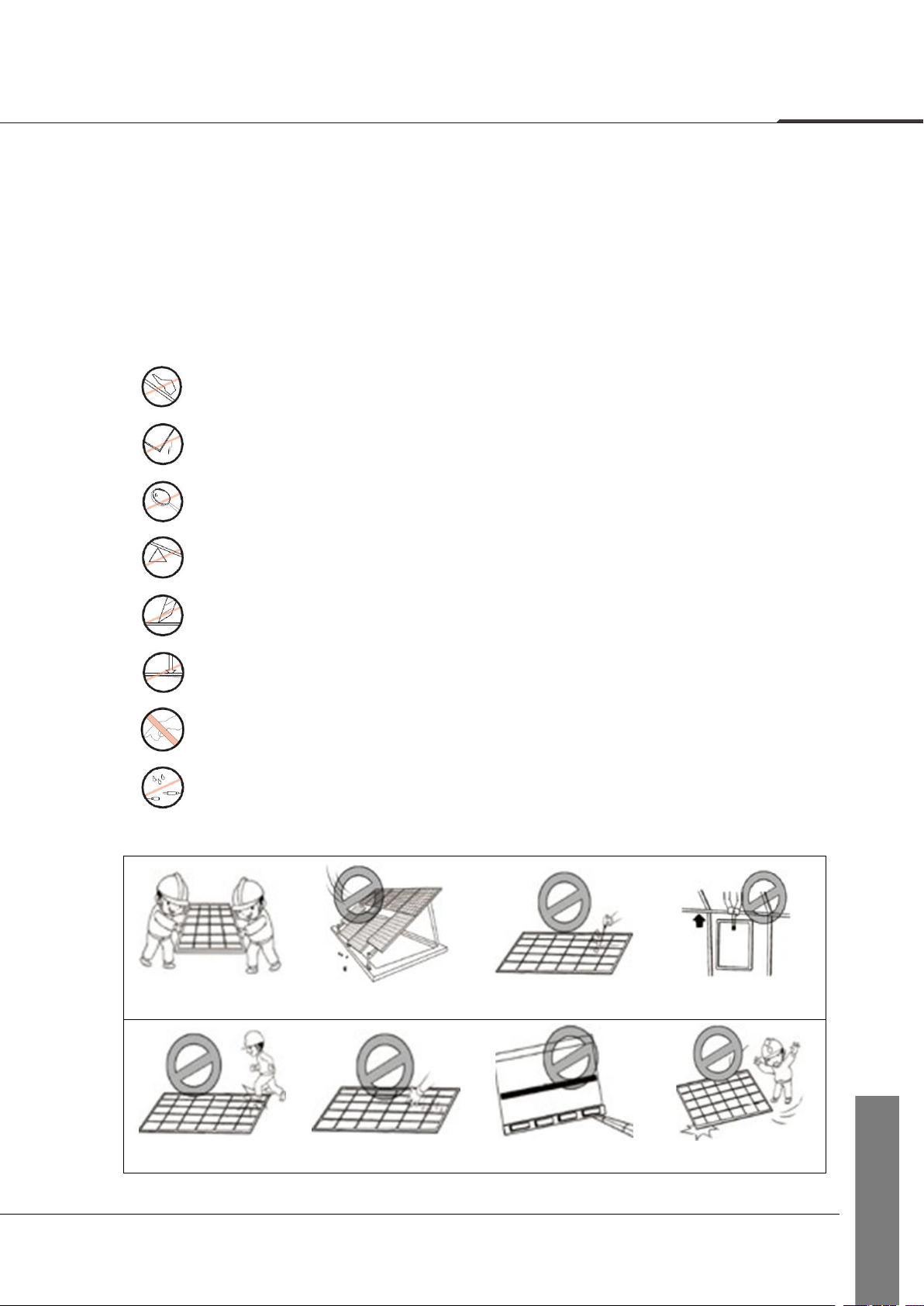
Unpacking description
1. In the outdoor unpacking process, it is prohibited to operate in rainy conditions;
2. If there is wind in the field, special attention shall be paid. Particularly in the event of
heavy wind, it is recommended not to handle the module, and it is necessary to properly
secure the unpacked Modules;
3. The working surface shall be such that the packing box can be placed in a stable, level
position, avoiding being overturned;
4. During the unpacking, it is necessary to wear protective gloves, and avoid scratching
the hands and leaving the fingerprints on the glass;
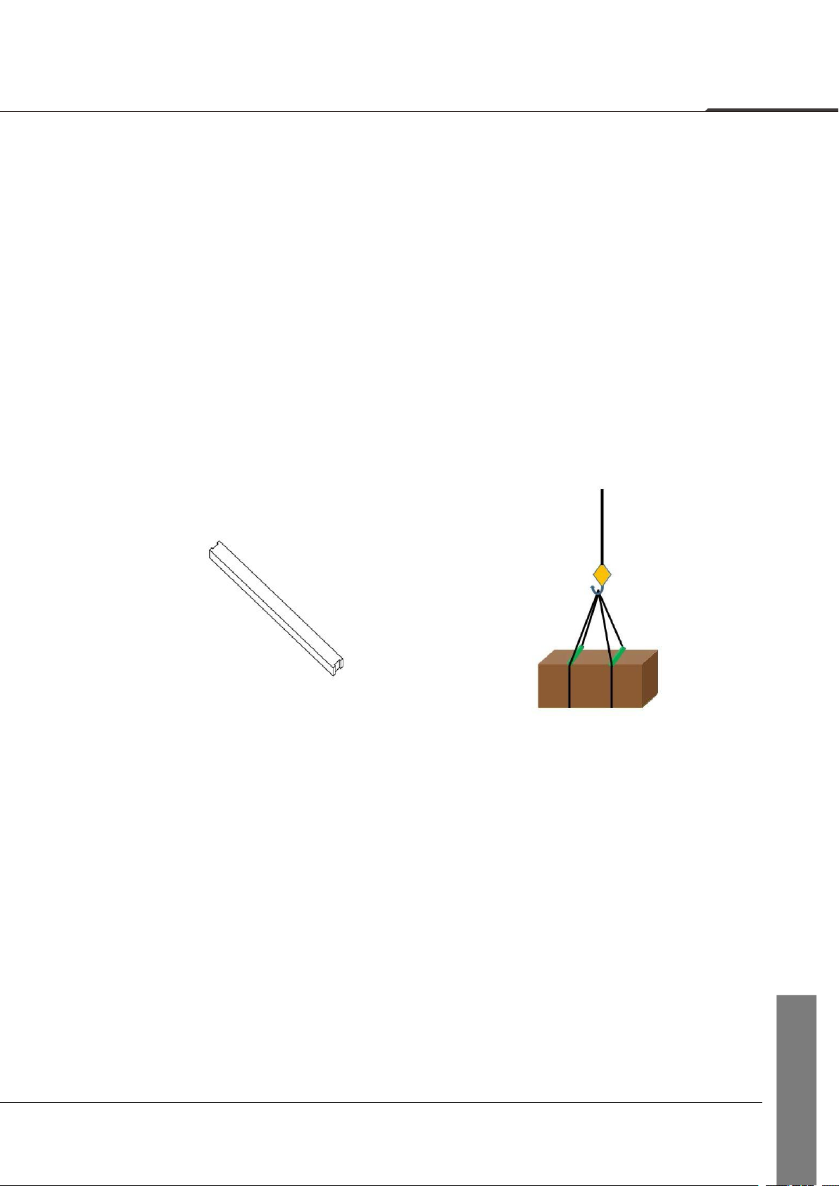
5. In the case of operation not according to the requirements or in the case of an
unskillful operation, it will result in the fall-off of the protective corner in small amounts,
which will be normal. The effect of the protective corner is to reduce damage due to external
force during transport, and the fall-off of the protective corner will not influence the reliability
of the Modules;
6. Before the unpacking, it is necessary to carefully check the product information on the
carton box, and carefully read the unpacking instruction;
7. Every module shall be carried by two people. When carrying the module by two
people, it is prohibited to pull the junction box.

TW solar energy Co., Ltd
08
MECHANICAL INSTALLATION
Location Selection
Select suitable places to install Modules.
Install Modules at the places with sufficient sunlight and without shade at any time. If a
module is shaded or even partially shaded, it will result in lower power output. A
permanent or regular shade will cause module damage, which will result in the invalidity
of product’s limited warranty.
Do not store, install or use Modules at the places where combustible gas is easily
generated or gathering.
The straight-line distance between the installation site and coastline shall not be shorter
than 1 km unless there is a written approval from TW or an engagement specified in the
contract.
Location Selection
Modules in the same string should be installed at the same angle. Modules installed in
different angles will receive different irradiation, which will cause current different. As a
result, it will decrease the operation efficiency of the system.

TW solar energy Co., Ltd
09
MECHANICAL INSTALLATION
Installation requirements
Ensure the module installation method and support system sufficiently robust, so that
the Modules can undertake the preset loading conditions, the support installer or
supplier shall provide necessary guarantee and other related certifications. The
installation support system shall pass the inspection and test by the third-party test
institution with the static mechanic analysis capability, and use the local national or
international standards, such as DIN1055 or equivalent.
The support structure shall be made of the durable, corrosion resistant and ultraviolet
resistant materials.
The module shall be firmly mounted on the support.
Choose proper installation height of the photovoltaic support system, and ensure the
lowest part of the module is high enough, to avoid being shaded by plant or being
damaged by the flying sand. Or being covered by snow for a long time in winter.
When the module is installed on the roof or the building, it is necessary to ensure that
the roof structure is fixed firmly and will not be damaged by heavy wind or heavy
snow, and the back of the module shall be well-ventilated to facilitate the cooling of
the module (the minimum gap between the module and installation surface is 10cm).
Considering the influence of linear thermal expansion of the module frame, the
minimum distance between two Modules should not be less than 10mm.
Ensure that the module backside will not contact the support or architectural structure
even if there is the module surface is under the external pressure.
It is required to observe the instruction guide and safety rules attached on the support.
It is not allowed to drill the hole in the glass surface or frame of the module.
otherwise ,the guarantee will be invalidated
When to install the Modules on the roof, it is necessary to guarantee the roof
structure is suitable for the module installation. And the installed modules should not
be beyond the roof zone. Additionally, the roof area where it is penetrated by module
installation shall be properly sealed to prevent the roof from water leakage.
When the module is installed on the supporting column, it is necessary to ensure the
supporting column and module installation structure is capable of withstanding the
expected local wind.

TW solar energy Co., Ltd
10
MECHANICAL INSTALLATION
Framed Modules
Installation with the mounting clamp
Table 1 Installation Method
Clamping
on the
long side
Installation Method A
Installation Method B
Clamping
on the
short side
Installation Method C
Installation Method D
Note: The length of the clamp≥50mm.

TW solar energy Co., Ltd
11
MECHANICAL INSTALLATION
Table 2 Installation method and load capacity
Classification
Installation method
Installation method A
Installation method B
Installation method C
Installation method D
Modules model
Height of
the frame
(mm)
Mounting
clamp
position
K
(mm)
Test load:
front/back,
(Pa)
Mounting
clamp
position
K
(mm)
Test load:
front/back,
(Pa)
Mounting
clamp
position
K
(mm)
Test load:
front/back,
(Pa)
Mounting
clamp
position
K
(mm)
Test load:
front/back,
(Pa)
Monofacial
Module
TWMPD-54HS
TWMPD-54HB
TWMND-54HS
B30
A/4±50
5400/2400
200~400
4000/2400
100~240
±1600
100~240
±1600
TWMPD-60HS
TWMND-60HS
B35
5400/2400
——
——
100~240
±1600
100~240
±1600
TWMPD-66HS
TWMND-66HS
B35
5400/2400
300~400
3600/2400
0~B/4
±1200
(special
clamp)
150~240
±1600
TWMPD-72HS
TWMND-72HS
B30
440
5400/2400
——
——
——
——
——
——
B35
A/4±50
5400/2400
——
——
0~B/4
±1200
(special
clamp)
——
——
TWMPF-50HS
TWMNF-50HS
B35
360~420
5400/2400
——
——
——
——
——
——
TWMPF-55HS
TWMNF-55HS
B35
440~540
5400/2400
——
——
——
——
——
——
TWMPF-54HS
TWMNF-54HS
B35
360~430
5400/2400
——
——
——
——
——
——
TWMPF-60HS
TWMNF-60HS
B35
360~420
5400/2400
365~435
3600/2400
45~485
±1000
——
——
TWMPF-66HS
TWMNF-66HS
B35
440~540
5400/2400
(special
clamp)
——
——
——
——
——
——
Bifacial
Module
TWMPD-60HD
TWMND-60HD
B30
A/4±50
5400/2400
A/4±50
5400/2400
——
——
——
——
TWMPD-66HD
TWMND-66HD
B30
5400/2400
5400/2400
——
——
——
——
TWMPD-72HD
TWMND-72HD
B30
5400/2400
5400/2400
——
——
——
——
B35
5400/2400
5400/2400
——
——
——
——
TWMPD-78HD
TWMND-78HD
B30
5400/2400
——
——
——
——
——
B35
5400/2400
——
——
——
——
——
TWMPF-50HD
TWMNF-50HD
B35
5400/2400
——
——
——
——
——
——
TWMPF-55HD
TWMNF-55HD
B35
5400/2400
275~375
3600/2400
——
——
——
——
TWMPF-54HD
TWMNF-54HD
B35
5400/2400
——
——
——
——
——
——
TWMPF-60HD
TWMNF-60HD
B35
5400/2400
360~420
3600/2400
——
——
——
——
TWMPF-66HD
TWMNF-66HD
TWMHF-66HD
B35
5400/2400
440~540
3600/2400
——
——
——
——
Note: Test load = γm(safety factors) × design load,some installation methods require special clamp.

TW solar energy Co., Ltd
12
MECHANICAL INSTALLATION
Installation with the mounting hole
Table 3 Installation Method
Mounting
on the
long side
Installation Method E
Installation Method F

TW solar energy Co., Ltd
11
13
MECHANICAL INSTALLATION
Table 4 Mounting dimension and load capacity
Classification
Modules model
Height of
the frame
(mm)
The mounting clamp position
M
(mm)
The mounting
clamp position
N
(mm)
Installation
Method E
Test load:
front/back
(Pa)
Installation
Method F
Test load:
front/back
(Pa)
Monofacial
Module
TWMPD-54HS
TWMPD-54HB
TWMND-54HS
B30
990
1085
5400/2400
——
1400
1085
5400/2400
5400/2400
TWMPD-60HS
TWMND-60HS
B35
990
1085
5400/2400
——
1400
1085
5400/2400
——
TWMPD-66HS
TWMND-66HS
B35
990
1085
5400/2400
——
1400
1085
5400/2400
——
TWMPD-72HS
TWMND-72HS
B30
1400
1096
5400/2400
——
B35
990
1085
5400/2400
——
1400
1085
5400/2400
——
TWMPD-78HS
TWMND-78HS
B35
1200
1085
5400/2400
——
TWMPF-50HS
TWMNF-50HS
B35
1400
1055
5400/2400
——
TWMPF-55HS
TWMNF-55HS
B35
1400
1055
5400/2400
3600/2400
TWMPF-54HS
TWMNF-54HS
B35
1400
1262
5400/2400
——
TWMPF-60HS
TWMNF-60HS
B35
1400
1262
5400/2400
3600/2400
TWMPF-66HS
TWMNF-66HS
B35
1400
1262
5400/2400
3600/2400
Bifacial
Module
TWMPD-60HD
TWMND-60HD
B30
1200
1096
5400/2400
5400/2400
1400
1096
5400/2400
±2400
TWMPD-66HD
TWMND-66HD
B30
1200
1096
5400/2400
±2400
1400
1096
5400/2400
5400/2400
TWMPD-72HD
TWMND-72HD
B30
1200
1096
5400/2400
±2400
1400
1096
5400/2400
5400/2400
B35
1200
1096
5400/2400
±2400
1400
1096
5400/2400
5400/2400
TWMPD-78HD
TWMND-78HD
B30
1200
1096
5400/2400
——
B35
1200
1096
5400/2400
——
TWMPF-50HD
TWMNF-50HD
B35
1400
1055
5400/2400
——
TWMPF-55HD
TWMNF-55HD
B35
1400
1055
5400/2400
3600/2400
TWMPF-54HD
TWMNF-54HD
B35
1400
1262
5400/2400
——
TWMPF-60HD
TWMNF-60HD
B35
1400
1262
5400/2400
3600/2400
TWMPF-66HD
TWMNF-66HD
TWMHF-66HD
B35
1400
1262
5400/2400
3600/2400
Note: Test load = γm(safety factors) × design load.

TW solar energy Co., Ltd
14
MECHANICAL INSTALLATION
The Modules may be installed and fixed with the following methods:
Mounting hole system: Use the corrosion-resistant bolt, for fixing with the installation
support through the installation hole in the side frame of the module, as shown in Fig. 3.
Figure 3 Mounting holes
Recommended bolt kits are as follows:
bolt kits
M8 bolt kits
Note
Bolt
M8
Material:Stainless
steel or
Hot galvanizing
Washer
2*M8
Spring Washer
M8
bolt tightening torque range:(N.m)
16~20

TW solar energy Co., Ltd
15
MECHANICAL INSTALLATION
Clamping system: use proper clamp, and fix the module with the installation support, as
shown in Fig. 4.
the clamp must maintain an overlap of unless 8 mm with the frame of the module(you can
change the cross section of the clamp if the module is securely installed). The applied value of
torque should refer to mechanical design standard and the bolt type customer is using, for
example: M8: 16-20 N•m.
Figure 4 Mounting clamps

TW solar energy Co., Ltd
16
ELECTRICAL INSTALLATION
DC power generated by the photovoltaic system can be converted into AC power and fed
into the grid. Policies on connecting renewable energy system to the grid vary from region to
region. Consult senior system designer before designing the system. Generally, the system
installation shall be formally approved by the local public sector.
General Installation
Installation structure should be compatible with module, in order to avoid galvanic
corrosion. Any defects caused by such corrosion will void the warranty.
The DC-side system potential of the photovoltaic array includes the practice of floating
ground, positive-pole grounding and negative-pole grounding according to the system
requirements; and different cell technologies have different adaptability. In a
power-station project, particularly the module of the crystalline silicon photovoltaic cells,
too large an absolute value of the negative to the ground might cause potential induced
degradation (PID). Consequently, it is appropriate to use the negative grounding system
so that the potential of the circuit is positive. Consult the inverter manufacturer for
details.
It is forbidden for non-professionals to open the lock nuts of the connector. Make sure
that the connectors are clean, dry and fully connected.
(A click sound should be heard when fully connected), otherwise it may lead to electric
arc sparks which will damage the connector or cause a fire.
Under normal conditions, a module is likely to experience conditions that produce more
current and/or voltage than reported at standard test conditions, Accordingly, the values
of ISC and VOC marked on the Module should be multiplied by a factor of 1.25 when to
determining component voltage ratings, current ratings, fuse sizes, and size of controls
connected to the PV output.
Completely cover the Modules with an opaque material to prevent electricity from being
generated during disassembling the conductors.
It is not allowed to use the Modules in different models in the same solar photovoltaic
system. When the Modules are connected in series, the voltage of every string shall not
be higher than the maximum voltage of the system (as shown in Figure 5). Reference
equation of the maximum number of the Modules in serial connection: maximum system
voltage of the module/ (1.25* open-circuit voltage).
When connected in parallel, the current output is equal to the sum of each string’s current
(as shown in Figure 6). Fuse is necessary for each module string. Take reference to the
local regulation. Recommended maximum parallel Modules configurations: Fuse rating/
(1.25* short-circuit current).

TW solar energy Co., Ltd
17
ELECTRICAL INSTALLATION
Figure 5 Connection in Series Figure 6 Connection in parallel
Refer to the local regulations to determine the system wire size, types and temperatures.
The cross section of the cables and the capacity of the connectors must be selected to suit
the maximum system short circuit current (The recommended section area for a single
piece of Module is 4 mm2, and the recommended rated current for the connector is greater
than 20A), otherwise the cables and connectors shall be overheated under large current.
Caution: The maximal temperature of the cable is 85 ℃while the upper limited
temperature of the connector is 105℃.
Make sure the electric components such as the connectors and inverters are off-state
during the installation. To reduce lightning damage, the loop area should be kept as small
as possible when laying cables. It is recommended to use fuses in each string.
This manual suits for next models
42
Table of contents
Other TW SOLAR Solar Panel manuals
Popular Solar Panel manuals by other brands

ENN Solar Energy
ENN Solar Energy EST-110 installation manual

Dometic
Dometic 9600010943 Installation and operating manual

Redilight
Redilight SPECTRA installation instructions

Thermo King
Thermo King ThermoLite T-Series installation guide

Nature Power
Nature Power 55701 manual

BayWa
BayWa closed II installation manual