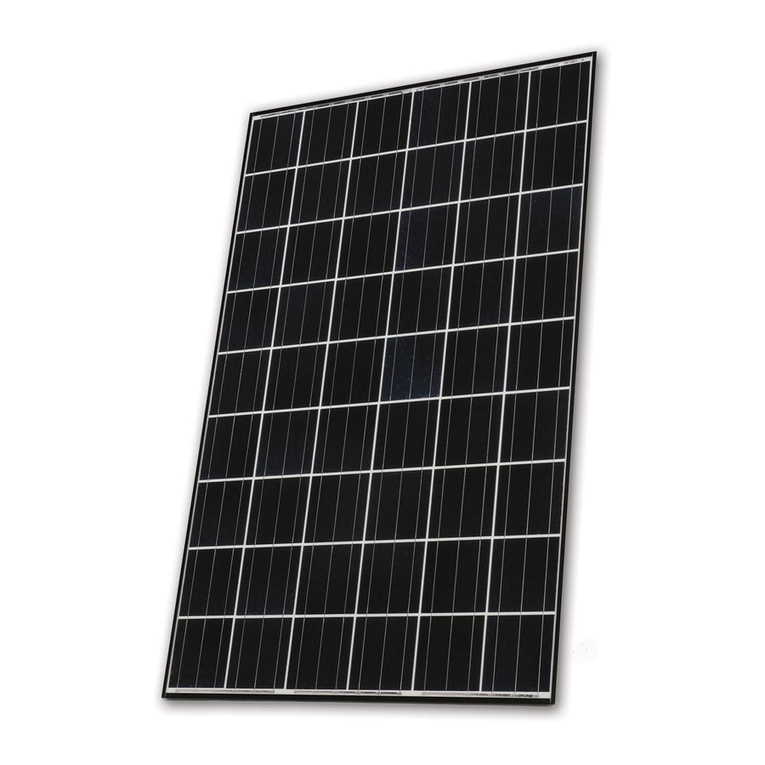
Solon Black 160/05 Instruction manual

SOLON Black 160/05
Assembly and Installation Instructions.
Assembly Instructions SOLON Black 160/05· EN

2

3
Table of contents
Introduction
Before you start 4
Safety instructions 5
Standards and regulations 7
Installation conditions 8
Mounting recommendations 9
Assembly
Exploded drawing 10
Preparation: Calculating the dimensions of the module area 11
Assembly Step 1: Roof battens (supporting battens) 12
Assembly Step 2: Mounting planks 14
Assembly Step 3: Mounting the modules 16
Assembly Step 4: Mounting planks for further vertical columns of modules 18
Assembly Step 5: Installation of a further column of modules 19
Assembly Step 6: Installing the sealing rubber 20
Assembly Step 7: Mounting planks for the final vertical column of modules 21
Assembly Step 8: Checking the electrical connection 23
Assembly Step 9: Mounting frame – mounting the front sheets 24
Assembly Step 10: Mounting the side sheets 27
Assembly Step 11: Mounting the upper sheets 29
Assembly Step 12: Final sealing measures 32
Additional Information
Maintenance and cleaning 34
Components 35

4
Before you start
Symbols used
Danger! Risk to life from electric shock
Warning! Risk of damage to product or environment
Note – Useful Information
Disclaimer
No guarantee or liability is taken for any damage which is caused
by improper installation.
Required components
Note
In addition to the delivered SOLON parts, various other parts are
needed at the site. For an overview of these components, please
refer to the assembly section.
Please read these assembly and installation instructions thoroughly before
you start the installation, operation or maintenance. Failure to comply with
these assembly and installation instructions can lead to personal injury or
material damage! Please keep these instructions safe.

Assembly Instructions SOLON Black 160/05 5
Safety instructions
General hazard warnings
Risk of life-threatening electric shock and arcing.
In particular, note for photovoltaic installations:
− There is always a voltage present on modules when in light.
− The modules can only be isolated at the DC-breaker; in the event
of a fault (short circuit, ground fault) the plant will continue
to operate on the DC-side.
− When opening contacts under load, unquenchable electric arcs can arise.
Do not insert any (electrically conductive) parts into the plugs or sockets
of the modules.
Do not attach solar modules and cables with wet or damp connectors.
All tools and working conditions should be dry.
Observe the mounting instructions of the inverter manufacturer.
Do not use any damaged modules.
Keep children away from modules, inverters and other electrical
components of the system.
Take extreme care with all work on the cabling.
Follow the safety instructions from the manufacturers of any other
plant components.
General Precautions
Do not remove any of the manufacturer’s fittings or the rating plate.
Do not disassemble the modules.
Do not expose the modules to artificially concentrated light.
Do not treat modules with paint or glue or use sharp objects.
Modules must not be cleaned using detergents/solvent-based cleaners.
Before construction, check the structural stability of the building and
of the system to be mounted.
The module is only for use under moderate climate conditions
(also see section Installation conditions).
This installation guide is only intended for skilled technicians.
The regulations of the relevant professional/trade associations apply
(BGV A1, BGV A2, BGV C22). We cannot accept any claims resulting
from DIY assembly and advise you to employ a specialist.

6
Warnings about temporary storage, removal
from the packaging and transportation
Always exercise extreme care when handling or moving the modules.
Always transport the modules in the provided packaging.
The modules must always be handled with both hands.
Wear gloves.
Do not use the connectors or the connection cables as a handle.
Avoid any flexing or sagging of the modules.
Do not put any weight on the modules, step on them or drop them.
Do not use sharp objects on the modules.
Keep all electrical contacts clean and dry.
Use dry rooms for temporary storage.
Do not place modules on the side spacers or the sealing lip.
Warning
The roof-integrated system must be grounded. Fix the grounding cable
(Cu, at least 16 mm, UV-resistant) to a suitable place on the mounting frame
and to the ground point of the building using an electrically conducting bolt
fastening. All sheet metal parts must be electrically connected together.
Note
In case of any later queries it is recommended that you make a note
of the serial numbers of the modules.

Assembly Instructions SOLON Black 160/05 7
Standards and regulations
In addition to any possible local regulations,
the following standards should be observed
DIN VDE 0100 Erection of power installations with rated voltages
up to 1,000 volts, all relevant parts, especially T712
VDE 0105 T100 Operation of Electrical Installations
VDI 6012 Bl. 2 Distributed Energy Systems in Buildings
VDE 0298 T4 Sheathed Cables
DIN 18382 Electric Cable and Conductor installation in Buildings
DIN 18334 Carpentry and Joinery
DIN 18338 Roof Covering and Roof Sealing
DIN 18339 Plumbing
DIN 18351 Construction on Building Facades
DIN 18451 Scaolding
DIN 1055 Load Assumptions for Structures
VDE 0185 Lightning
DIN EN 61724 Monitoring the operational performance
of photovoltaic systems
DIN V VDE V 01261-1 Automatic isolation points for PV systems
Accident prevention provisions of the professional associations
BGV A1 General regulations
BGV A2/A3 Electrical installations and equipment
BGV C22 Construction (Personal protective equipment against falls)
BGV D36 Ladders and Steps
Please ensure before and during the assembly that the local standards,
building and safety regulations are adhered to.
Note
The standards and regulations given are just a selection and are not to be
taken as a complete list. (As of: 03/2009)
German regulations for roofing engineers
Technical connection conditions (TAB) for connections to
the low-voltage grid network of electrical power operators
VDEW-Guidelines “Private generators connected to the low-voltage
grid network”

8
The sizing of the module SOLON Black 160/05 is based on the guidelines
provided by DIN 1055, DIN EN 1991-1-Parts 1-4.
The module SOLON Black 160/05 fulfills the weather protection functions
of a traditional sloping roof when the following conditions are met:
Roof inclination of 22° to 60°
The roof must meet current technological and construction
standards and regulations, e.g.:
• rmlymounted,stableroofbattens
• waterproofsarking/underlay
The construction work is performed by a specialist, and all points
in this manual have been carefully observed (constructed in accordance
with the instructions)
When installing the modules the following points must be observed:
Adequate rear ventilation of the modules to prevent power loss due to
build up of heat. This can be improved by the additional use of vented tiles.
Modules are not to be installed in the vicinity of flammable gases and
vapors (e.g. gas containers, gas/petrol stations, paint spraying equipment).
Module should not be installed near open flames and flammable materials.
Module is not to be exposed to concentrated light.
Module is not to be exposed to very salty (recommended at least 500 m
from sea) and sulfurous (volcano) conditions, otherwise there is a risk of
corrosion.
Module is not to be mounted as overhead glazing or as a façade element.
Installation conditions

Assembly Instructions SOLON Black 160/05 9
Mounting recommendations
Orientation and inclination
W a r n i n g !
Please note the installation conditions for this module type when determining
the installation tilt.
Modules in Europe are best mounted in a south direction. The optimal tilt
of modules in Central Europe is about 30°. In Northern Europe, the optimum
angle of tilt is slightly steeper; in Southern Europe somewhat flatter. Devia-
tions from the optimal direction and tilt will reduce the energy yield of the
system. For a guide you can use the following graphic.
Percentage energy vs roof orientation
Shadow-free location
A module is considered shadow-free if all the year round its full area remains
free of shadow and sunlight can fall on it unhindered. Even small partial
shadowing such as from chimneys, antennas, buildings, trees (allowing for
growth) and street lamps will lead to a reduction in yield. Therefore, the
modules should be installed in a place where the shadowing during the course
of the day is minimized or can be completely excluded. In some cases, this
might require a shadow analysis using a simulation program or a sun-position
analyzer.
Note
Even temporary shadow from dirt (dust and grime, bird droppings, leaves)
can lead to a reduction in yield. Instructions about removal of this dirt are
described in the chapter “Maintenance”.
Rear ventilation
The performance of modules decreases with rising temperature. Therefore
reliable rear ventilation should be ensured. A performance-reducing build
up of heat can be reduced through the use of vented tiles.

10
4l 4h 4i
5b
4g
4e
4f
4c
4k
4d
3
2
4b
5a
4a
1
4m
4h 4i
4m
4b
2
4k
Exploded drawing
D a n g e r !
Work on a photovoltaic system requires special expertise and should only be
carried out by suitably qualified and authorized personnel. Observe the safety
precautions and warnings in the sections 'Safety instructions and Regulations'
at all times.
Warning!
The roof must comply with the applicable standards and regulations.
Roof battens, raers and sarking must be in perfect condition.
Tools required for installation of the modules
Cordless
screwdriver
Pliers Crimping tool/
Pincers
Angle grinder
with diamond
wheel
Multimeter Hammer
Note
For easier insertion of the sealing rubber the use of neutral detergent
with a sponge/brush is recommended.
Note
These assembly and installation instructions describe the assembly
from le to right. It is also possible to start assembly from the right.

Assembly Instructions SOLON Black 160/05 11
Note
The modules, including the metal sheets, can only be installed in areas
of the roof that are free from variations in slope.
Roof tiles
At least two roof tiles must remain around the area in which the modules
will be installed.
Modules
The modules have dimensions of 1.71 x 0.85 m (height x width).
A gap of 0.01 m must be maintained between the modules.
Sheets
An additional space of 0.12 m (2 x 0.06 m) is required for the side sheets.
For the front and top sheets an additional space of about 0.40 m
must be calculated into the height of the module area.
Preparation: Calculating the
dimensions of the module area
Note
Two roof tiles or slates are needed above and below
the calculated module area.
Note
Two supplementary roof tiles or slates are needed
on the le and right of the calculated module area.
Calculating the width of the module area
Number of modules x 0.85 m =
+ Number of modules - 1 x 0.01 m =
+ 2 side sheets 0.12 m =
=Result
Example: 8 modules side-by-side
8 x 0.85 m = 6.80 m
+ 8 - 1 x 0.01 m = 0.07 m
+ 0.12 m = 0.12 m
=6.99 m
With eight modules the module area will be 6.99 m
wide from the right-hand to the le-hand tile edges
(plus four roof tiles).
Calculating the height of the module area
Number of modules x 1.71 m =
+ 0.40 m =
=Result
Example: 3 stacked modules
3 x 1.71 m = 5.13 m
+ 0.40 m = 0.40 m
=5.53 m
The module area with three stacked modules will
be 5.53 m high (plus four roof tiles).

12
Assembly Step 1: Roof battens
(supporting battens)
Note
The roof battens (supporting battens) are not included and must be provided
on site. The supporting battens secure the module to the roof.
Number
Overall, you need five rows of roof beams/battens. The length of each is calcu-
lated from the number of side-by-side modules x 0.86 m. In case your module
area is wider than the commercially available roof battens, the total length can
be made up from from shorter pieces.
2 modules 5 rows of battens à 1.72 m 6 modules 5 rows of battens à 5.16 m
3 modules 5 rows of battens à 2.58 m 7 modules 5 rows of battens à 6.02 m
4 modules 5 rows of battens à 3.44 m 8 modules 5 rows of battens à 6.88 m
5 modules 5 rows of battens à 4.30 m
Warning!
Protect any cut edges of the supporting battens against mold etc. by using
suitable wood preservatives.
Cover the roof space according to the required roof surface.
Note
In the first stage, two supporting battens will be assembled in the lower sec-
tion. These serve to prevent the modules sliding during subsequent assembly.
The use of straight roof battens eases the following assembly steps!
8
9
8
First screw the lower support batten (8) using wood
screws (not provided, 9) to the counter-battens or raers.

Assembly Instructions SOLON Black 160/05 13
While doing this, ensure that the distance (lower edge) to the underlying batten
is between 190 and 210 mm. In case there are existing roof tiles, the distance
between the support batten and the top edge of the existing tiles must be
170 mm. The lateral separation to the roof tiles must be at least 50 mm.
8
8
9
Warning!
The height of the double supporting battens can exceed the height of the
existing roof battens by a maximum of 43 mm.
Double-up the mounted supporting batten (8) using a
further supporting batten (8) with screws (9).

14
Assembly Step 2: Mounting planks
The mounting planks are used to attach the modules. They are to be screwed
vertically onto the roof battens.
Note
The mounting planks and the corresponding screws are not provided.
Warning!
Impregnated planks with a thickness of 24 mm and a width of 140 mm
to 180 mm are to be used.
Warning!
Ensure you use the correct length of screw. Screws which are too short
may lead to an insecure system. Screws which are too long can damage
the waterproof underlay.
Length
Planks 1.71 m long are required for each module.
1 module 1.71 m
2 modules 3.42 m
3 modules 5.13 m
4 modules 6.84 m
5 modules 8.55 m
Length of the mounting planks vs number of stacked modules
Warning!
Protect any cut edges of the mounting planks against mold etc. using
suitable wood preservatives.
Number
Two mounting planks plus a further, final mounting plank are required per
column of modules for each module area. The number of mounting planks
is calculated as follows: Number of module columns x 2 + 1.
Number of
module
columns
Number
of mounting
planks
2 5
3 7
4 9
511
613
715
817
Number of mounting planks per module column
Number of
module
columns
Number
of mounting
planks
919
10 21
11 23
12 25
13 27
14 29
15 31
Number of
module
columns
Number
of mounting
planks
16 33
17 35
18 37
19 39
20 41

Assembly Instructions SOLON Black 160/05 15
7
9
7
Fix the le mounting plank (7) onto the roof battens
with screws (9), ensuring that the distance from the le
edge of the mounting plank to the roof is 50 mm.
Then fix the middle mounting plank (7) with screws (9)
onto the roof battens, making sure that the distance
from the center of the mounting plank to the outer-le
edge of the le-hand mounting plank is 440 mm.
Fix the right-hand mounting plank (7) with screws (9)
onto the roof battens. Make sure that the distance
from the center of the right-hand mounting plank to
the center of the mounting plank is 430 mm.
Note
Should the module area be higher than the mounting planks used, they
can be extended vertically by fitting many mounting planks together.
Warning!
When fitting mounting planks vertically together, make sure that:
− no module screws subsequently lie on the plank joins
− they are screwed to at least two roof battens

16
Assembly Step 3: Mounting
the modules
W a r n i n g !
Do not apply high forces to the modules e.g. by standing on them or using
them as supports during the entire assembly process!
1
7
8
8
2
1
Place the first SOLON Black 160/05 (1) on the mounting planks (7) and
carefully let it slide down to the double support batten (8).
Align the module laterally, parallel to the roof tiles.
Note
The mounting plank should protrude at least 10 mm and up to
max. 20 mm from the module edge.
Check the orientation of the module (1) in relation to the roof and
correct if needed.
Fix the module (1) to the mounting planks (7) using the
delivered SOLON hexagonal wood screws (2) and sealing
washers.

Assembly Instructions SOLON Black 160/05 17
1
7
1
Warning!
Make sure the cables are laid under the mounting planks. The modules must
not lie on the cables.
Position the second SOLON Black 160/05 (1) on the mounting planks (7)
above the first module. Electrically connect the modules (1) to each other
using the provided plugs according to the connection plan.
1
7
1
7
2
Align the second module (1) to the side of the roof and fix
it using the delivered SOLON hexagonal wood screews
(2) with sealing washers on the mounting planks (7).
Repeat these assembly steps for each further horizontal row of modules.

18
7
9
9
7
For the next vertical column of modules fasten the
middle mounting plank (7) with screws (9) to the roof
battens. During this ensure that the distance from the
center of the mounting plank to the edge of the module
is 430 mm.
Screw the next (right-hand) mounting plank (7) with
screws (9) to the roof battens. Ensure that the distance
from the center of the right-hand mounting plank to the
center of the middle plank is 430 mm.
Note
If necessary extend the mounting planks vertically by fitting them together.
Warning!
When fitting mounting planks vertically together, make sure that:
− no module screws subsequently lie on the plank joins
− they are screwed to at least two roof battens
Assembly Step 4: Mounting planks for
further vertical columns of modules

Assembly Instructions SOLON Black 160/05 19
7
1
Place the lower SOLON Black 160/05 (1) on the mounting planks (7) to the
right of the already mounted module and push together. The 10 mm spacing
between the modules is set by the two side spacers.
Warning!
Ensure that the cables are laid under the mounting planks. The modules must
not lie on the cables.
Electrically connect the modules (1) to each other, using the provided plugs
according to the connection plan.
Fix the module (1) to the mounting planks (7) using the delivered
SOLON hexagonal wood screws (2) with sealing washers.
Repeat these assembly steps for each further module (1) to be fixed.
Assembly Step 5: Installation
of a further column of modules

20
Assembly Step 6: Installing the
sealing rubber
Note
In order to ease assembly, mount the sealing rubber immediately aer
you have installed two adjacent columns of modules.
Note
To simplify assembly, moisten the underside of the sealing rubber with
lubricant (e.g. dish-washing detergent).
1
1
3
Press the SOLON sealing rubber (3) flush into the gap between the modules
(1) from top to bottom.
If necessary, cut-o superfluous sealing rubber below the lower sealing lip.
The loose end is to be fixed at the last step of the framework assembly.
Table of contents
Other Solon Solar Panel manuals
Popular Solar Panel manuals by other brands

GOAL ZERO
GOAL ZERO NOMAD 100 user guide

sunjoe
sunjoe SJ1440SP Original instructions

Panasonic
Panasonic VBHNxxxSJ25 series General installation manual

Sanyo
Sanyo HIT-N220E01 General installation manual

Nature Power
Nature Power 14002 owner's manual

Energetica
Energetica E-2000 Series Operating and installation guide