Solorder HF2420S40-75 User manual

All-in-one solar charge inverter 1
All-in-one solar charger inverter
User Manual
Product models:
HF2420S40-75 | HF2420S60-100 | HF2420U60-100
HF2430S40-75 | HF2430S60-100 | HF2430U60-100

All-in-one solar charge inverter 2
Important safety instructions
Please keep this manual for future use.
This manual contains all safety, installation and operating instructions for the HF Series all-in-one solar
charge inverter.
Please read all instructions and precautions in the manual carefully before installation and use.
Non-safety voltage exists inside the all-in-one solar charge inverter. To avoid personal injury, users
shall not disassemble the all-in-one solar charge inverter themselves. Contact our professional
maintenance personnel if their is a need for repair.
Do not place the all-in-one solar charge inverter within the reach of children.
Do not install the all-in-one solar charge inverter in harsh environments such as moist, oily,
flammable or explosive, or heavily dusty areas.
The mains input and AC output are high voltage, so please do not touch the wiring terminals.
The housing of the all-in-one solar charge inverter is hot when it is working. Do not touch it.
Do not open the terminal protective cover when the all-in-one solar charge inverter is working.
It is recommended to attach proper fuse or circuit breaker to the outside of the all-in-one solar
charge inverter.
Always disconnect the fuse or circuit breaker near the terminals of PV array, mains and battery
before installing and adjusting the wiring of the all-in-one solar charge inverter.
After installation, check that all wire connections are tight to avoid heat accumulation due to poor
connection, which is dangerous.
The all-in-one solar charge inverter is off-grid. It is necessary to confirm that it is the only input
device for load, and it is forbidden to use it in parallel with other input AC power to avoid damage.

All-in-one solar charge inverter 3
CONTENTS
1. GENERAL INFORMATION .............................................................................................................4
1.1 PRODUCT OVERVIEW AND FEATURES................................................................................................... 4
1.2 BASIC SYSTEM INTRODUCTION ........................................................................................................... 5
1.3 APPEARANCE .................................................................................................................................6
2. INSTALLATION INSTRUCTIONS ....................................................................................................7
2.1 INSTALLATION PRECAUTIONS ............................................................................................................. 7
2.2 WIRING SPECIFICATIONS AND CIRCUIT BREAKER SELECTION......................................................................8
2.3 INSTALLATION AND WIRING.............................................................................................................11
3. OPERATING MODES..................................................................................................................17
3.1 CHARGING MODE ......................................................................................................................... 17
3.2 OUTPUT MODE.............................................................................................................................18
4. LCD SCREEN OPERATING INSTRUCTIONS ...................................................................................19
4.1 OPERATION AND DISPLAY PANEL .....................................................................................................19
4.2 SETUP PARAMETERS DESCRIPTION ...................................................................................................22
4.3 BATTERY TYPE PARAMETERS ...........................................................................................................28
5. OTHER FUNCTIONS...................................................................................................................29
5.1 DRY NODE ...................................................................................................................................30
5.2 RS485/CAN COMMUNICATION PORT ..............................................................................................30
5.3 USB COMMUNICATION PORT .......................................................................................................... 30
6. PROTECTION ............................................................................................................................31
6.1 PROTECTIONS PROVIDED ................................................................................................................31
6.2 FAULT CODE MEANING...................................................................................................................33
6.3 HANDLING MEASURES FOR PART OF FAULTS .......................................................................................34
7. SYSTEM MAINTENANCE............................................................................................................35
8. TECHNICAL PARAMETERS .........................................................................................................36

All-in-one solar charge inverter 4
1. General information
1.1 Product overview and features
HF series is a new all-in-one hybrid solar charge inverter, which integrates solar energy storage &
means charging energy storage and AC sine wave output. Thanks to DSP control and advanced control
algorithm, it has high response speed, high reliability and high industrial standard. Four charging
modes are optional, i.e. Only Solar, Mains Priority, Solar Priority and Mains & Solar hybrid charging;
and two output modes are available, i.e. Inverter and Mains, to meet different application requirements.
The solar charging module applies the latest optimized MPPT technology to quickly track the
maximum power point of the PV array in any environment and obtain the maximum energy of the
solar panel in real time.
Through a state of the art control algorithm, the AC-DC charging module realizes fully digital voltage
and current double closed loop control, with high control precision in a small volume. Wide AC voltage
input range and complete input/output protections are designed for stable and reliable battery
charging and protection.
Based on full-digital intelligent design, the DC-AC inverter module employs advanced SPWM
technology and outputs pure sine wave to convert DC into AC. It is ideal for AC loads such as
household appliances, power tools, industrial equipment, and electronic audio and video equipment.
The product comes with a segment LCD display design which allows real-time display of the operating
data and status of the system. Comprehensive electronic protections keep the entire system safer and
more stable.
Features:
1. Full digital voltage and current double closed loop control, advanced SPWM technology, output
of pure sine wave.
2. Two output modes: mains bypass and inverter output; uninterrupted power supply.
3. Available in 4 charging modes: Only Solar, Mains Priority, Solar Priority and Mains & Solar hybrid
charging.
4. Advanced MPPT technology with an efficiency of 99.9%.
5. Designed with a LCD screen and 3 LED indicators for dynamic display of system data and
operating status.
6. ON/OFF rocker switch for AC output control.
7. Power saving mode available to reduce no-load loss.
8. Intelligent variable speed fan to efficiently dissipate heat and extend system life.
9. Lithium battery activation by PV solar or mains, allowing access of lead-acid battery and lithium
battery.
10. 360 °all-round protection with a number of protection functions.
11. Complete protections, including short circuit protection, over voltage and under voltage
protection, overload protection, reverse protection, etc.

All-in-one solar charge inverter 5
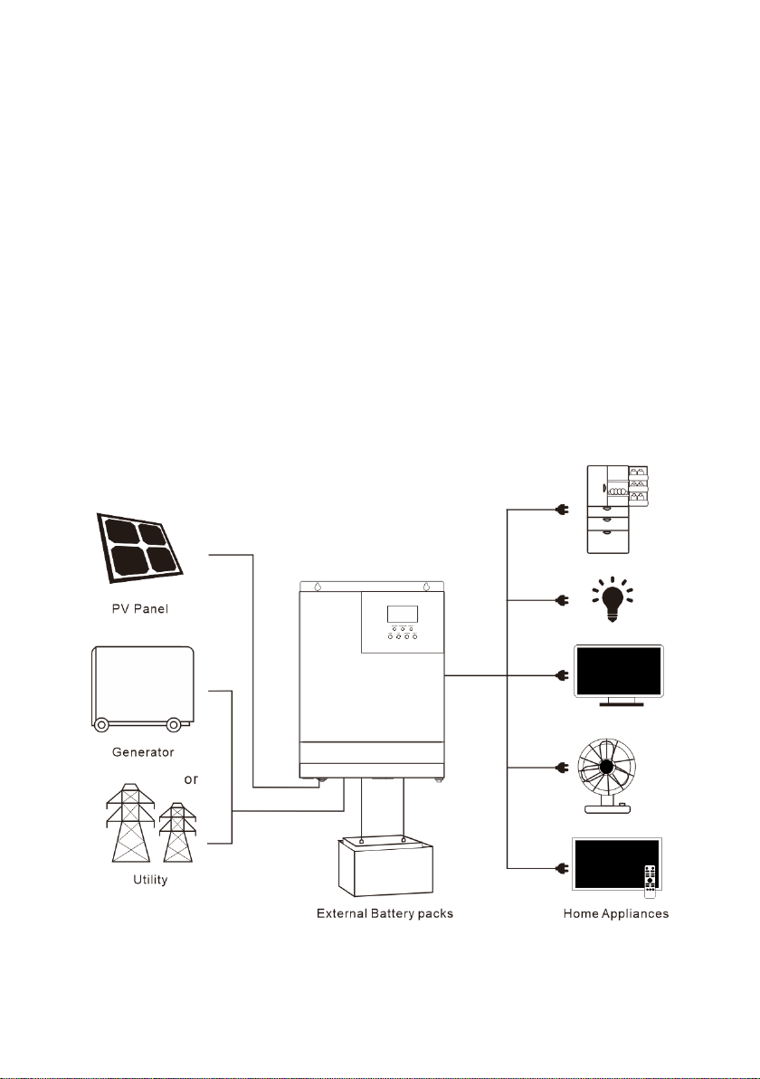
1.2 Basic system introduction
The figure below shows the system application scenario of this product. A complete system consists of
the following parts:
1. PV module: Convert light energy into DC power, and charge the battery through the all-in-one
solar charge inverter, or directly invert into AC power to drive the load.
2. Mains or generator: Connected at the AC input, to power the load while charging the battery. If
the mains or generator is not connected, the system can also operate normally, and the load is
powered by the battery and PV module.
3. Battery: Provided to ensure normal power supply to the system loads when solar energy is
insufficient and the Mains is not connected.
4. Household load: Allow connection of various household and office loads, including refrigerators,
lamps, TVs, fans and air conditioners.
5. All-in-one solar charge inverter: The energy conversion unit of the whole system.
Specific system wiring method depends on the actual application scenario.

All-in-one solar charge inverter 6
1.3 Appearance
①
AC input port
⑨
Battery port
②
AC output port
⑩
ON/OFF rocker switch
③
USB communication port
⑪
PV port
④
RS485/CAN communication port
⑫
Touch button
⑤
Dry node port
⑬
LED Indicator
⑥
Grounding screw hole
⑭
LCD screen
⑦
AC input Overload protector
⑧
Cooling fan

All-in-one solar charge inverter 7
2. Installation instructions
2.1 Installation precautions
Please read this manual carefully prior to installation to familiarize yourself with the installation
steps.
Be very careful when installing the battery. Wear safety goggles when installing a lead-acid
liquid battery. Once coming into contact with the battery acid, rinse with clean water timely.
Do not place metal objects near the battery to prevent short-circuit of the battery.
Acid gas may be generated when the battery is charged. So, please ensure good ventilation.
When installing the cabinet, be sure to leave enough space around the all-in-one solar
charge inverter for heat dissipation. Do not install the all-in-one solar charge inverter and
lead-acid battery in the same cabinet to avoid corrosion by acid gas generated during
battery operation.
Only the battery that meets the requirements of the all-in-one unit can be charged.
Poorly connected connections and corroded wires may cause great heat which will melt the
wire insulation, burn the surrounding materials, and even cause fires. So, make sure the
connectors have been tightened, and the wires are secured with ties to avoid looseness of
connections caused by shaking of wires during mobile application.
The system connection wires are selected according to a current density of not more than 5
A/mm2.
Avoid direct sunlight and rainwater infiltration for outdoor installation.
Even after the power is turned off, there is still high voltage inside the unit. Do not open or
touch the internal components, and avoid related operations until the capacitor completely
discharges.
Do not install the all-in-one solar charge inverter in harsh environments such as moist, oily,
flammable or explosive, or heavily dusty areas.
Polarity at the battery input end of this product shall not be reversed, otherwise it may
damage the device or cause unpredictable danger.
The mains input and AC output are high voltage, so please do not touch the wiring
terminals.
When the fan is working, do not touch it to prevent injury.
Load equipment input power needs to confirm that this all-in-one solar charge inverter is
the only input device, and it is forbidden to use in parallel with other input AC power to
avoid damage. It is necessary to confirm that the solar charge inverter is the only input
device for load equipment, and it is forbidden to use it in parallel with other input AC power
to avoid damage.

All-in-one solar charge inverter 8
2.2 Wiring specifications and circuit breaker selection
Wiring and installation must comply with national and local electrical codes.
Recommended PV array wiring specifications and circuit breaker selection: Since the output current of
the PV array is affected by the type, connection method and illumination angle of the PV module, the
minimum wire diameter of the PV array is calculated according to its short-circuit current; refer to the
short-circuit current value in the PV module specification (the short-circuit current is constant when
the PV modules are connected in series; the short-circuit current is the sum of the short-circuit currents
of all PV modules connected in parallel); the short-circuit current of the PV array shall not exceed the
maximum input current.
Refer to the table below for PV input wire diameter and switch:
Models
Recommended PV
wiring diameter
Maximum PV
input current
Recommended air switch or
circuit breaker type
HF2420S40-75
6mm2/10AWG
30A
2P—40A
HF2420S60-100
8mm2/8AWG
40A
2P—63A
HF2420U60-100
8mm2/8AWG
40A
2P—63A
HF2430S40-75
6mm2/10AWG
30A
2P—40A
HF2430S60-100
8mm2/8AWG
40A
2P—63A
HF2430U60-100
8mm2/8AWG
40A
2P—63A
Note: The voltage in series shall not exceed the maximum PV input open circuit voltage.

All-in-one solar charge inverter 9
Refer to the table below for recommended AC input wire diameter and switch:
Models
Recommended AC
input wiring diameter
Maximum bypass
input current
Recommended air switch or
circuit breaker type
HF2420S40-75
6mm2/10AWG
30A
2P—40A
HF2420S60-100
6mm2/10AWG
30A
2P—40A
HF2420U60-100
8mm2/8AWG
40A
2P—63A
HF2430S40-75
6mm2/10AWG
30A
2P—40A
HF2430S60-100
6mm2/10AWG
30A
2P—40A
HF2430U60-100
8mm2/8AWG
40A
2P—63A
Note: There is already an appropriate circuit breaker at the Mains input wiring terminal, so it is
not necessary to add one more.
Recommended battery input wire diameter and switch selection
Models
Recommended
battery wiring
diameter
Rated battery
discharge
current
Maximum
charge
current
Recommended air
switch or circuit breaker
type
HF2420S40-75
20mm2/4AWG
100A
90A
2P—120A
HF2420S60-100
25mm2/3AWG
100A
120A
2P—140A
HF2420U60-100
25mm2/3AWG
100A
100A
2P—120A
HF2430S40-75
30mm2/2AWG
140A
120A
2P—160A
HF2430S60-100
30mm2/2AWG
140A
140A
2P—160A
HF2430U60-100
30mm2/2AWG
140A
100A
2P—160A

All-in-one solar charge inverter 10
Recommended AC output wiring specifications and circuit breaker selection
Models
Recommended
AC output wiring
diameter
Rated
inverter AC
output
current
Maximum
bypass output
current
Recommended air
switch or circuit breaker
type
HF2420S40-75
6mm2/10AWG
8.6A
30A
2P—40A
HF2420S60-100
6mm2/10AWG
8.6A
30A
2P—40A
HF2420U60-100
8mm2/8AWG
16.7A
40A
2P—63A
HF2430S40-75
6mm2/10AWG
13A
30A
2P—40A
HF2430S60-100
6mm2/10AWG
13A
30A
2P—40A
HF2430U60-100
8mm2/8AWG
25A
40A
2P—63A
Note: The wiring diameter is for reference only. If the distance between the PV array and the all-in-one
solar charge inverter or the distance between the all-in-one solar charge inverter and the battery is
relatively long, using a thicker wire can reduce the voltage drop to improve system performance.
Note: The above are only recommended wiring diameter and circuit breaker. Please select the
appropriate wiring diameter and circuit breaker according to actual situations.

All-in-one solar charge inverter 11
2.3 Installation and wiring
Installation steps::
Step 1: Determine the installation position and the space for heat dissipation. Determine the
installation position of the all-in-one solar charge inverter, such as wall surface; when installing the all-
in-one solar charge inverter, ensure that there is enough air flowing through the heat sink, and space
of at least 200m to the left and right air outlets of the inverter shall be left to ensure natural convection
heat dissipation. Refer to the installation diagram of the whole machine as above.
Warning: Danger of explosion! Never install the all-in-one solar charge inverter and lead-acid
battery in the same confined space! Also do not install in a confined place where battery gas may
collect.

All-in-one solar charge inverter 12
Step 2: Remove the terminal cover
Step3: Wiring
AC input / output wiring method:
①Prior to AC input/output wiring, disconnect the external circuit breaker and confirm that the
wire used is thick enough. Please refer to Section 2.2 “Wiring Specifications and Circuit Breaker
Selection”;
②Properly connect the AC input wire according to the wire sequence and terminal position
shown in the figure below. Please connect the ground wire first, and then the live wire and the
neutral wire;

All-in-one solar charge inverter 13
:Ground L:Live N:Neutral
③Properly connect the AC output wire according to the wire sequence and terminal
position shown in the figure below. Please connect the ground wire first, and then the live
wire and the neutral wire. The ground wire is connected to the grounding screw hole on
the cabinet through the O-type terminal.
:Ground L:Live N:Neutral
Note: The grounding wire shall be as thick as possible (cross-sectional area is not less than
4mm2). The grounding point shall be as close as possible to the all-in-one solar charge inverter.
The shorter the grounding wire, the better.

All-in-one solar charge inverter 14
PV input wiring method:
①Prior to wiring, disconnect the external circuit breaker and confirm that the wire used
is thick enough. Please refer to Section 2.2 “Wiring Specifications and Circuit Breaker
Selection”;
②Properly connect the PV input wire according to the wire sequence and terminal
position shown in the figure below.
PV+: PV input positive pole PV-: PV input negative pole
BAT wiring method:
①Prior to wiring, disconnect the external circuit breaker and confirm that the wire used
is thick enough. Please refer to Section 2.2 “Wiring Specifications and Circuit Breaker
Selection”. The BAT wire needs to be connected to the machine through the O-type
terminal. The O-type terminal with an inner diameter of 5 mm is recommended. The O-
type terminal shall firmly press the BAT wire to prevent excessive heat generation caused
by excessive contact resistance;
②Properly connect the BAT wire according to the wire sequence and terminal position
shown in the figure below.

All-in-one solar charge inverter 15
BAT+: Battery positive electrode BAT-: Battery negative electrode
Warnings:
①Mains input, AC output and PV array will generate high voltage. So, before wiring, be sure to
disconnect the circuit breaker or fuse;
②Be very careful during wiring; do not close the circuit breaker or fuse during wiring, and ensure that
the “+”and “-”pole leads of each component are connected properly; a circuit breaker must be
installed at the battery terminal. Refer to Section 2.2 “Wiring Specifications and Circuit Breaker
Selection”to select a right circuit breaker. Before wiring, be sure to disconnect the circuit breaker to
prevent strong electric sparks and avoid battery short circuit; if the all-in-one solar charge inverter is
used in an area with frequent lightning, it is recommended to install an external lightening arrester at
the PV input terminal.
Step 4: Check if the wiring is correct and firm. In particular, check if the battery polarity is reversed, if
the PV input polarity is reversed and if the AC input is properly connected.

All-in-one solar charge inverter 16
Step 5: Install the terminals cover.
Step 6: Turn on the all-in-one solar charge inverter
First, close the circuit breaker at the battery terminal, and then turn the rocker switch
on the left side of the machine to the "ON" state. The "AC/INV" indicator flashing
indicates that the inverter is working normally. Close the circuit breakers of the PV
array and the Mains. Finally, turn on AC loads one by one as the AC output is normal
to avoid a protection action caused by a large momentary shock due to simultaneous
turning on the loads simultaneously. Now, the machine goes into a normal
operation according to the set mode.
Note: If power is supplied to different AC loads, it is recommended to first turn on the load with a
large surge current. After the load is stable, turn on the load with a small surge current.
Note: If the all-in-one solar charge inverter does not work properly or the LCD or indicator is abnormal,
refer to Chapter 6 to handle the exceptions.

All-in-one solar charge inverter 17
3. Operating modes
3.1 Charging mode
1) PV priority: PV module will charge the battery preferentially, and the battery is charged by the
Mains only when the PV system fails. During the day, solar energy is fully used to charge, while at
night, it converts to the Mains. This can maintain battery level, and is ideal for areas where the
grid is relatively stable and electricity price is relatively high.
2) Mains priority: The Mains supply is preferentially used to charge the battery. Only when the Mains
fails, the PV charging can be activated.
3) Hybrid charging: PV and mains hybrid charging. PV MPPT charging is a priority, and when PV
energy is insufficient, the mains supply supplements. When the PV energy is sufficient again, the
mains stops charging. This is the fastest charging mode, suitable for the areas where power grid
is unstable, providing sufficient backup power supply at any time.
4) Only Solar (Only Solar): Only PV charging, without Mains charging. This is the most energy-
efficient way in which battery is charged only by solar panels, and is usually used in areas with
good lighting conditions.

All-in-one solar charge inverter 18
3.2 Output mode
PV priority mode:
Switch to mains supply when the PV charging fails. This mode maximizes the use of solar energy
while maintaining battery power, suitable for use in the areas with relatively stable grid.
Mains priority mode:
Switch to inverter only when the mains fails (when there was mains power, switch to mains
power for charging and power supply).Then, the unit is equivalent to a backup UPS, suitable for
areas with unstable grid. Switching does not affect PV charging.
Inverter priority mode:
Switch to mains supply only when the battery discharge undervoltage is lower than the set point
(item 04). When the charging battery is higher than the set point of (05 setting item), switch to
the battery discharge mode. This can cycle the battery charge and discharge. This mode
maximizes the use of DC power and is used in the area with stable grid. Switching does not
affect PV charging.

All-in-one solar charge inverter 19
4. LCD screen operating instructions
4.1 Operation and display panel
The operation and display panel is as shown below, including 1 LCD screen, 3 indicators and 4
operation buttons.
Operation buttons introduction
Indicators introduction
Function
buttons
Description
SET
Enter/Exit Settings menu
UP
Previous choice
DOWN
Next choice
ENT
Confirm/Enter Options under the settings menu,
Indicators
Colors
Description
AC/INV
Yellow
Steady on: Mains output
Flash: Inverter output
CHARGE
Green
Flash: Battery charging
Steady on: Charging completed
FAULT
Red
Steady on: Fault state

All-in-one solar charge inverter 20
LCD screen introduction
Icons
Functions
Icons
Functions
Indicates that the AC input
terminal has been connected to
the grid
Indicates that the inverter circuit
is working
Indicates that the AC input mode
in APL mode (wide voltage range)
Indicates that the machine is in
the Mains Bypass mode
Indicates that the PV input terminal
has been connected to the solar
panel
Indicates that the AC output is in
an overload state
Indicates that the machine has
been connected to the battery:
indicates that the remaining
battery is 0%~24%;
indicates that the remaining
battery is 25%~49%;
indicates that the remaining
battery is 50%~74%;
indicates that the remaining
battery is 75%~100%.
Indicates the percentage of AC
output loads:
indicates that the load
percentage is 0%~24%;
indicates that the load
percentage is 25%~49%,
indicates that the load
percentage is 50%~74%,
indicates that the load
percentage is ≥75%.
Indicates that the battery type of
the machine is a lithium battery
Indicates that the buzzer is not
enabled
This manual suits for next models
5
Table of contents
Popular Inverter manuals by other brands

Toshiba
Toshiba ACE-tronics G9 ASD quick start guide

Audiovox
Audiovox ADC150 owner's manual

Conrad Electronic
Conrad Electronic 2497614 Important information

Xantrex
Xantrex GT100 Series Planning and installation manual

XCSOURCE
XCSOURCE UES-2410 user manual

Mitsubishi Electric
Mitsubishi Electric FR-LU08 instruction manual