SOLU TRONIC SOLPLUS 25-55 User manual

MV/ 2012-01 Version: A6
Kurzanleitung SP 25-55, Brief Installation Manual SP 25-55,
Instrucciones de instalación SP 25-55, Brevi istruzioni per
l´installazione SP 25-55, Instructions d´installation série SP 25-55
Kurzanleitung SOLPLUS 25-55
Brief Installation Manual SOLPLUS 25-55
Instrucciones de instalación SOLPLUS 25-55
Brevi istruzioni per l’installazione SOLPLUS 25-55
Instructions d’installation série SOLPLUS 25-55

SP25-55_Kurzinstallationsanleitung_DEFSI_A6_2012-01-12 2/23
Kurzanleitung SP 25-55, Brief Installation Manual SP 25-55,
Instrucciones de instalación SP 25-55, Brevi istruzioni per
l´installazione SP 25-55, Instructions d´installation série SP 25-55
Inhaltsverzeichnis/Table of contents/ /Contenido/Indice/Sommaire
1. Allgemeines/ General/ Aspectos generales/ Generale/ Général 3
2. Sicherheitsvorschriften/Safety instructions/Los reglamentos de seguridad/Codice di
sicurezza/Instructions de sécurité 5
3. Lieferumfang/ Scope of delivery/Volumen entrega/Contenuto della confezione/Accessoires
livrés 6
4. Montage 6
4.1 Sie benötigen/ Tools you need/Adicionalmente necesitará/ Sono necessari/ Vous avez 6
besoin en plus
4.2 Markieren der Bohrlöcher/ Mark the drill holes/ Marca los taladros/ Marcare punti dove 7
trapanare/ Marquer l’emplacement des trous
4.3 Löcher bohren/ Drill holes/ Taladra los agujeros/ Buca alesaggio/ Faire les trous 7
4.4 Dübel einsetzen/ Insert the wall plugs/ Introducir los tacos/ Introdurre tassello/ Insérer les
chevilles 8
4.5 Montagewinkel anschrauben/ Fix the mounting bracket/ Fijar el ángulo de montaje/
Fissare alla parete la staffa/ Fixer le équerre démontage 8
4.6 Aufhängen/ Hang inverter on bracket/Colgar a la pared/Appendere/Accrocher 9
4.7 Festschrauben von unten/ Fix knurled screws from below/ Fijar tornillos deste abajo/
Avvitare das basso/ Visser en-dessous 9
4.8 Erdanschluss/Ground connection/Toma de tierra/Connessione alla terra/Mise à la terre 10
4.9 Befestigungsstelle am Wechselrichter/ Connection point on inverter/ Punto de connecion
al inversor/ Punto di fissaggio per I’inverter/ Emplacement de la connexion 10
4.10 Anschließen des 3-adrigen Netzsteckers/ Grid connection with 3-wire power plug/
Connectar el enchufe de 3 hilos/ Collegamento alla spina a 3 fili/ Connecter la fiche de
contact de 3 fils 10
4.11 AC-Anschlüsse/ AC connector/ Conector AC/ AC nella presa/ Connecter AC 12
4.12 DC-Anschluss/ DC connector/ Conector DC/ DC nella presa/Connector DC 12
4.13 Anschalten/ Power on/Encender/Accendere/Enclencher 12
5. Setup-Menü/ Setup menu/ Menu de paramétrage/ Menu du setup/ Menú de configuración 13
5.1 Setup Menü 13
5.2 Setup menu 15
5.3 Menu de paramétrage 17
5.4 Menu du setup 19
5.5 Menú de configuración 21
SP25-55_Kurzinstallationsanleitung_DEFSI_A6_2012-01-12 3/23
Kurzanleitung SP 25-55, Brief Installation Manual SP 25-55,
Instrucciones de instalación SP 25-55, Brevi istruzioni per
l´installazione SP 25-55, Instructions d´installation série SP 25-55
1 Allgemeines
General
Aspectos generales
Generale
Général
Allgemeines
Bei Schäden infolge von Nichtbeachtung der Warnhinweise in dieser Betriebsanleitung übernimmt die
Solutronic AG keine Haftung. Vor der Inbetriebnahme sind die Betriebs-, Wartungs- und
Sicherheitshinweise durchzulesen. Wenn die Dokumentation in der vorliegenden Sprache nicht
einwandfrei verstanden wird oder zugänglich ist, fragen Sie bitte bei Ihrem Lieferanten nach und
informieren Sie diesen.
General
Solutronic AG assumes no liability for damage caused by failure to observe warnings given in the
operating instructions. Before starting to operate the inverter, read the operating instructions, warnings
and safety regulations thoroughly first. If you are not able to understand the language used in this
documentation sufficiently, please contact and inform the supplier of the situation.
Aspectos generales
En caso de daños a causa de la no observación de las indicaciones de seguridad de este manual de
instrucciones Solutronic AG no asume ninguna responsabilidad. Antes de la puesta en
funcionamiento deberán leerse las indicaciones de manejo, mantenimiento y seguridad. Si no
entendiera perfectamente la documentación redactada en este idioma pregunte e informe a su
proveedor.
Generale
Solutronic AG non si ritiene responsabile di danni causati dalla mancata osservanza delle regole di
sicurezza date in queste istruzioni operative. Prima di iniziare ad operare con l’apparecchiatura, si
devono leggere per intero le istruzioni operative, gli avvertimenti e le norme di sicurezza. Se la
documentazione nella presente lingua non fosse perfettamente comprensibile, per favore informare il
fornitore e richiedere ulteriori informazioni.
Général
Solutronic AG ne prend pas en charge les dommages dus au non-respecte des instructions décrites
dans la documentation. Avant de mettre l’appareil en marche, lire attentivement la documentation. Au
cas où la documentation ne serait pas compréhensible, ou si elle devait manquer, veuillez contacter
votre fournisseur et l’en informer.

SP25-55_Kurzinstallationsanleitung_DEFSI_A6_2012-01-12 4/23
Kurzanleitung SP 25-55, Brief Installation Manual SP 25-55,
Instrucciones de instalación SP 25-55, Brevi istruzioni per
l´installazione SP 25-55, Instructions d´installation série SP 25-55
Warnung
Warning
Aviso
Avviso
Attention
Unsachgemäßer Umgang mit diesen Geräten und Nichtbeachten der
angegebenen Warnhinweise sowie unsachgemäße Eingriffe in die
Sicherheitseinrichtung können zu Sachschaden, Körperverletzung,
elektrischem Schlag oder im Extremfall zum Tod führen.
Inappropriate treatment of this equipment and failure to observe
warnings given, as well as inappropriate tampering with the safety
features, can cause damage to the equipment, bodily injury, electric
shock or, in extreme cases, lead to death.
Un uso inadecuado de estos aparatos y el no respetar las indicacion
es de aviso aquí dadas así como manipulaciones en el dispositivo
de seguridad pueden causar daños materiales, lesiones, descargas
eléctricas y en caso extremo la muerte
Il trattamento improprio di questa apparecchiatura, la mancata
osservanza degli avvertimenti qui dati, o l’errato abbinamento con i
dispositivi di sicurezza, possono causare danni all’apparecchiatura,
ferite, shock elettrico o in casi estremi la morte.
Un usage non-conforme, ou non-respect des instructions ainsi
qu’une manipulation dans le dispositif de sécurité peuvent
endommager l’appareil, occasionner des blessures, ou même
engendrer un danger de mort par haute tension.
Warnung
Warning
Aviso
Avviso
Attention
Hohe elektrische Spannung durch falschen Anschluss! Lebens-
gefahr oder Körperverletzung durch elektrischen Schlag.
High voltage due to incorrect connection! Risk of fatal or bodily
injury from electric shock.
¡Alta tensión a causa de una falsa conexión! Peligro de muerte o
lesiones por descarga eléctric.
L’errata connessione può produrre alta tensione! Pericolo per la vita
o rischio di scossa elettrica.
Une mauvaise connection peut provoquer des hautes tensions
risquede blessures ou danger de mort!
Vorsicht
Caution
Precaución
Cautela
Attention
Heiße Oberfläche auf Gerätegehäuse möglich! Verletzungsgefahr!
Verbrennungsgefahr!
The surface of the inverter housing may be hot! Risk of injury! Very
hot! Do not touch!
¡Posibilidad de superficie caliente
en la carcasa del aparato!
¡Peligro de lesión! ¡Peligro de abrasión!
La superficie dell’apparecchiatura può riscaldarsi. Pericolo di
ferimento e incendio!
La surface de l’appareil peut devenir très chaude : risque de
blessure ou de brûlure!
SP25-55_Kurzinstallationsanleitung_DEFSI_A6_2012-01-12 5/23
Kurzanleitung SP 25-55, Brief Installation Manual SP 25-55,
Instrucciones de instalación SP 25-55, Brevi istruzioni per
l´installazione SP 25-55, Instructions d´installation série SP 25-55
2 Sicherheitsvorschriften
Safety instructions
Los reglamentos de seguridad
Codice di sicurezza
Instructions de sécurité
2)
Sicherheitsvorschriften
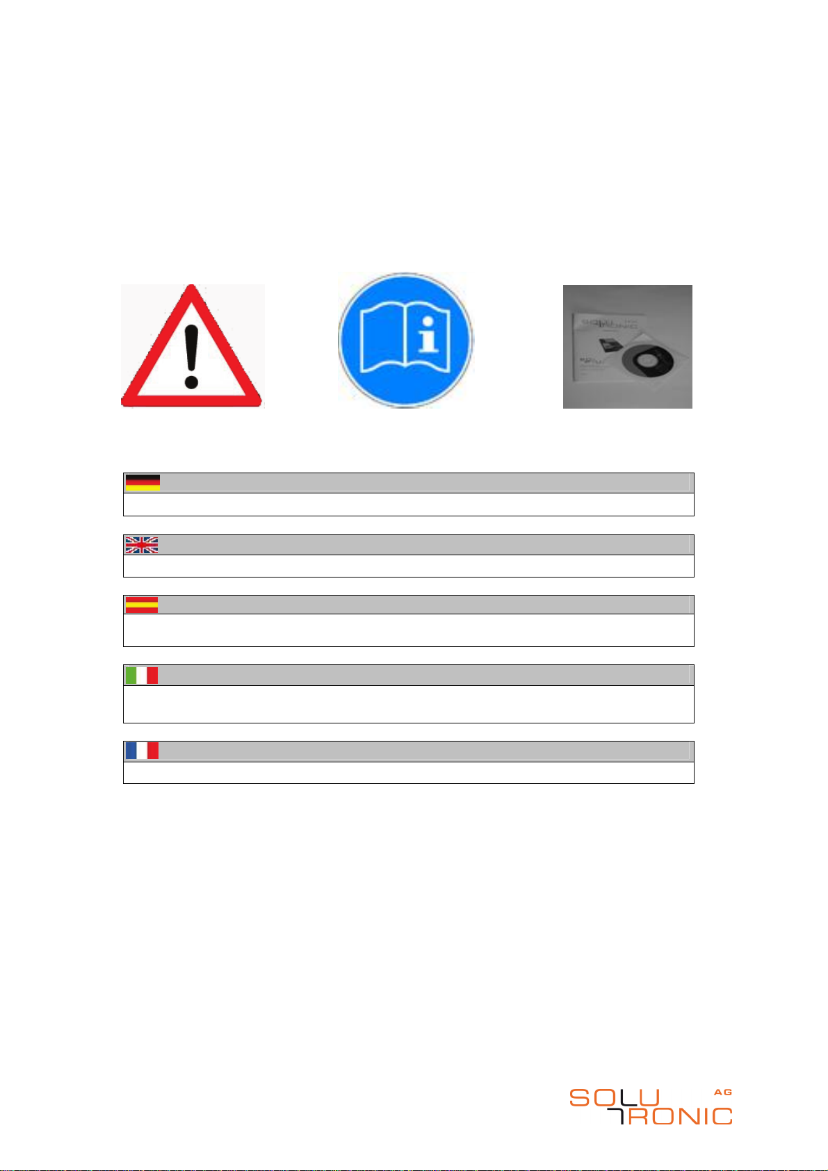
Wichtig! Installationsvorschriften in der Gerätedokumentation beachten.
2)
Safty instructions
Important! Please follow the installation instructions in the instruction manual.
2)
Los reglamentos de seguridad
Importante! Observar las instrucciones de instalación en la documentación del
dispositivo.
2)
Codice di sicurezza
Importante! Attenersi alle prescrizioni per l’installazione contenute nella
documentazione dell’apparecchio.
2)
Instructions de sécurité
Important! Suivre les prescriptions d’installation sur la documentation de l’appareil.

SP25-55_Kurzinstallationsanleitung_DEFSI_A6_2012-01-12 6/23
Kurzanleitung SP 25-55, Brief Installation Manual SP 25-55,
Instrucciones de instalación SP 25-55, Brevi istruzioni per
l´installazione SP 25-55, Instructions d´installation série SP 25-55
4 Montage/mounting/montage
montaggio/montaje
3 Lieferumfang 4.1 Sie benötigen
Scope of delivery Tools you need
Volumen entrega Adicionalmente necesitará
Contenuto della confezione Sono necessari
Accessoires livrés Vous avez besoin en plus
3) Lieferumfang 4) Sie benötigen
Installationsanleitung auf CD
SOLPLUS Wechselrichter
AC-Stecker
2 Innnensechskant-Schrauben M5x20
2 Schraubklemmen
Montagewinkel
Bohrmaschine
4 Schrauben
4 Dübel
Erdungskabel
Schraubendreher
Innensechskantschlüssel Größe3mm
3) Scope of delivery 4) You need
Installation Manual/CD
SOLPLUS inverter
AC connector
2 hexagon socket screws M5x20
2 plug in screw-type
Mounting bracket
Drill
4 screws
4 wall plugs
Earthing cable
Screwdriver
Key for hexagon socket screws 3 mm
3) Volumen entrega 4) adicionalemente necessitara
Documentación del dispositivo/CD
Inversor SOLPLUS
Connector AC
2 tornillos M5x20
2 el tornillo moleteado
Bornes de conexión
taladradora
4 tornillos
4 tacos
conector de tierra
el desarmador
Llave allen 3 mm
3) Contenuto della confezione 4) Sono necessari
Documentazione dell’apparecchio/CD
Inverter SOLPLUS Staffa per il montaggio
Spina AC
2 bullone a testa esagonale
2 bullone a testa esagonale M5x20
Binario per il montaggio
Trapano
4 viti con tasselli
4 rondelle
Salva vita
Cacciavite
brugola 3 mm Cavo messo a terra
3) Accessoires livrés 4) Vous avez besoin en plus
Documentation de l’ appareil/CD
Onduleur SOLPLUS
1 connecteur AC
2 vis inbus M5x20
2 bornes à vis
Équerre de montage
Perceuse
4 vis
4 chevilles
Câble de terre
Tournevis
Clé six pans 3 mm

SP25-55_Kurzinstallationsanleitung_DEFSI_A6_2012-01-12 7/23
Kurzanleitung SP 25-55, Brief Installation Manual SP 25-55,
Instrucciones de instalación SP 25-55, Brevi istruzioni per
l´installazione SP 25-55, Instructions d´installation série SP 25-55
4.2 Markieren der Bohrlöcher 4.3 Löcher bohren
Mark the drill holes Drill holes
Marca los taladros Taladra los agujeros
Marcare punti dove trapanare Buca alesaggio
Marquer l’emplacement des trous Faire les trous
Schritt 5-6
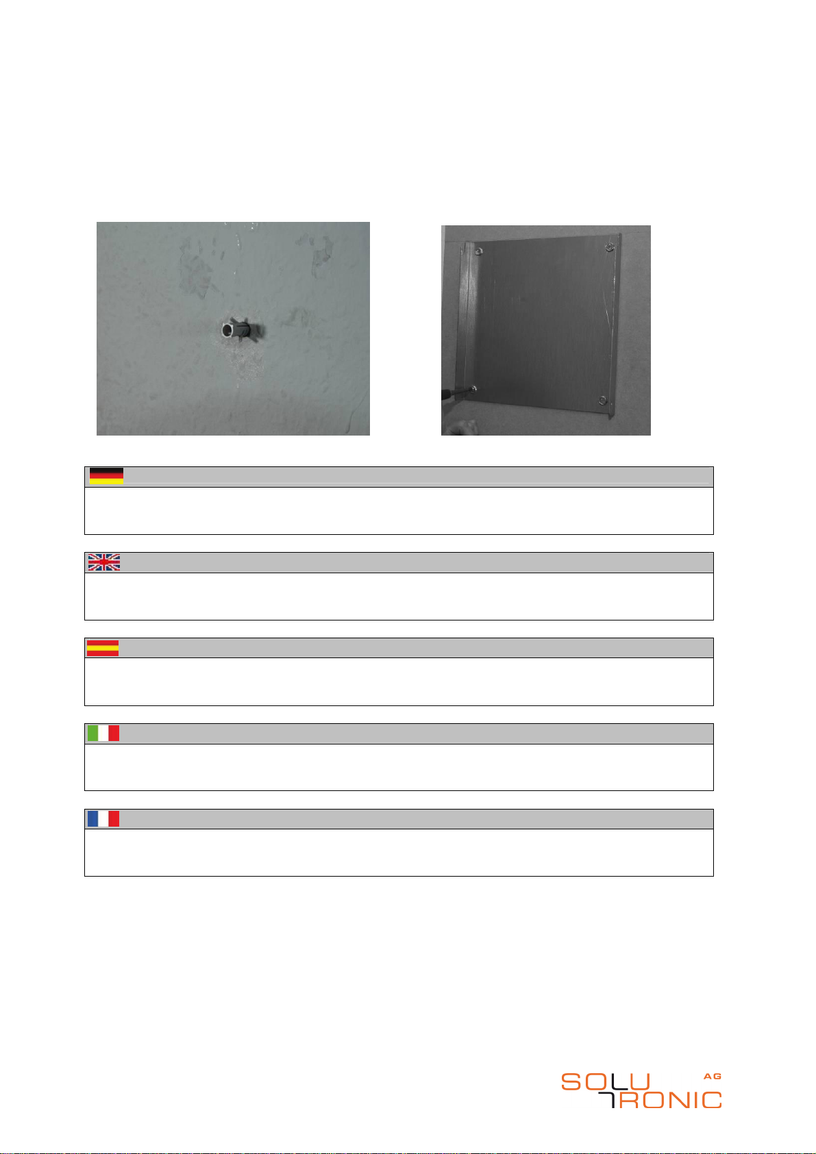
Anzeichnen der 4 Bohrlöcher.
Mit einem Bohrer die Löcher bohren (Bohrdurchmesser sowie Bohrtiefe entsprechend der
Wandverhältnisse und Schrauben wählen).
Step 5-6
Mark the 4 drill holes.
Drill holes. Please use a drill that is suitable for the material (wood, stone, concrete) of the
mounting position of the inverter and has the correct diameter and length.
Paso 5-6
Marcado de los 4 taladros.
Taladra los agujeros (el diámetro de la broca y la profundidad del agujero se ajusta a las
condiciones de la pared tal como a los tornillos que se va a usar).
Passo 5-6
Marcare i 4 punti dove trapanare.
Utilizzare il tipo di punta idonea al materiale da forare (muro, legno, cemento). Utilizzare
una punta di lunghezza e diametro adeguato ai tasselli adoperati.
Pas 5-6
Marquer les 4 trous à percer.
Avec une perceuse faire les trous. (Choisir diamètre et profondeur du trou ainsi que les vis
selon les caractéristiques de la paroi).
SP25-55_Kurzinstallationsanleitung_DEFSI_A6_2012-01-12 8/23
Kurzanleitung SP 25-55, Brief Installation Manual SP 25-55,
Instrucciones de instalación SP 25-55, Brevi istruzioni per
l´installazione SP 25-55, Instructions d´installation série SP 25-55
4.4 Dübel einsetzen 4.5 Montagewinkel anschrauben
Insert the wall plugs Fix the mounting bracket
Introducir los tacos Fijar el ángulo de montaje
Introdurre tassello Fissare alla parete la staffa
Insérer les chevilles Fixer le équerre démontage
Schritt 7-8
Dübel einsetzen.
Den Montagewinkel mit Schrauben an der Wand befestigen.
Step 7-8
Insert the wall plugs.
Attach the mounting bracket to the wall using the screws.
Paso 7-8
Introducir los tacos.
Fijar el rail de montaje a la pared con los tornillos.
Passo 7-8
Introdurre tassello.
Fissare alla parete la staffa per il montaggio servendosi delle viti.
Pas 7-8
Insérer les chevilles.
Fixer le équerre démontage sur la paroi à l’aide des vis.
SP25-55_Kurzinstallationsanleitung_DEFSI_A6_2012-01-12 9/23
Kurzanleitung SP 25-55, Brief Installation Manual SP 25-55,
Instrucciones de instalación SP 25-55, Brevi istruzioni per
l´installazione SP 25-55, Instructions d´installation série SP 25-55
4.6 Aufhängen 4.7 Festschrauben von unten
Hang inverter on bracket Fix knurled screws from below
Colgar a la pared Fijar tornillos deste abajo
Appendere Avvitare das basso
Accrocher
Visser en-dessous
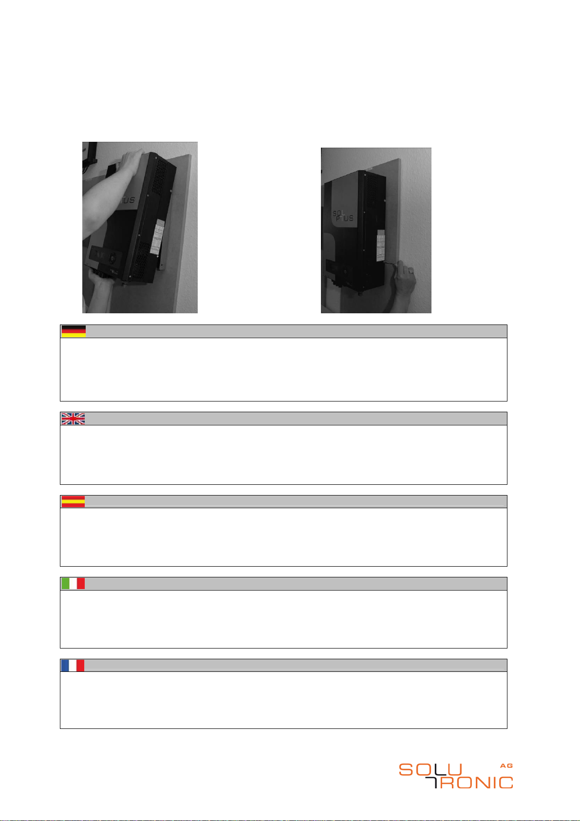
Schritt 9-10
Hängen Sie den Wechselrichter von oben in den Montagewinkel ein. Der Winkel befindet sich dann
zwischen den äußersten Rippen des Kühlkörpers. Die beiden mitgelieferten Schrauben M5x20 werden zur
Fixierung des Wechselrichters unten durch den Kühlkörper in die entsprechenden Löcher des
Montagewinkels geschraubt. Sie benötigen hierzu einen Innensechskant-Schlüssel. Um die Schrauben
einzudrehen, kann es notwendig sein, daß das Gerät 1-2mm angehoben werden muss. Überprüfen Sie
das Gerät auf festen Sitz!
Step 9-10
Hang the inverter from above on to the mounting bracket. The bracket will then be positoned between the
outermost slats of the heat sink. Now screw the two M5x20 screws supplied through the heat sink and into
the corresponding holes in the mounting bracket in order to fix the inverter in place. You will require an
Allen key to do this. It may be necessary to lift the unit by 1 - 2 mm in order to be able to screw the screws
without resistance. Check that the inverter is attached securely to the bracket!
Paso 9-10
Cuelgue el inversor en el soporte de montaje introduciéndolo por arriba. El soporte se encuentra entonces
entre las aletas exteriores del disipador de calor. Los dos tornillos M5x20 suministrados son atornillados
para fijar el inversor por debajo a través del disipador de calor en los agujeros correspondientes del
soporte de montaje. Para ello necesita una llave inbus. Es posible que sea necesario levantar el aparato
aprox. 1-2 mm para poder enroscar los tornillos sin esfuerzo. Compruebe que el aparato esté bien fijado.
Passo 9-10
Appendere l’inverter dall’alto sul supporto di montaggio. Il supporto si inserirà tra le lamelle più estreme
del dissipatore. Le due viti fornite M5x20, devono essere ora avvitate nei corrispondenti fori del supporto
di montaggio attraverso il dissipatore per fissare l’inverter in posizione. Per fare questo è necessaria una
chiave a brugola. Può essere necessario sollevare l’unità di 1 o 2 mm per poter avvitare le viti senza
resistenza. Controllare che l’apparecchiatura risulti ben fissata al supporto ed alla parete!
Pas 9-10
Suspendre l’onduleur dans le rail de montage qui se trouve entre les ailerons extérieurs du radiateur. Les
deux vis M5x20 servent à la fixation de l’onduleur à travers les ailes de refroidissements et à travers les
trous se trouvant vers le bas du rail de montage. Pour ce travail vous avez besoin de la clé six pans,
peut-être qu’il est nécessaire de soulever l’onduleur de 1 à 2 mm pour pouvoir passer les vis sans peine
dans les trous. Assurez-vous que l’appareil est bien fixé!
SP25-55_Kurzinstallationsanleitung_DEFSI_A6_2012-01-12 10/23
Kurzanleitung SP 25-55, Brief Installation Manual SP 25-55,
Instrucciones de instalación SP 25-55, Brevi istruzioni per
l´installazione SP 25-55, Instructions d´installation série SP 25-55
4.8 Erdanschluss 4.9 Befestigungsstelle am Wechselrichter
Ground connection Connection point on inverter
Toma de tierra Punto de connecion al inversor
Connessione alla terra Punto di fissaggio per I’inverter
Mise à la terre Emplacement de la connexion
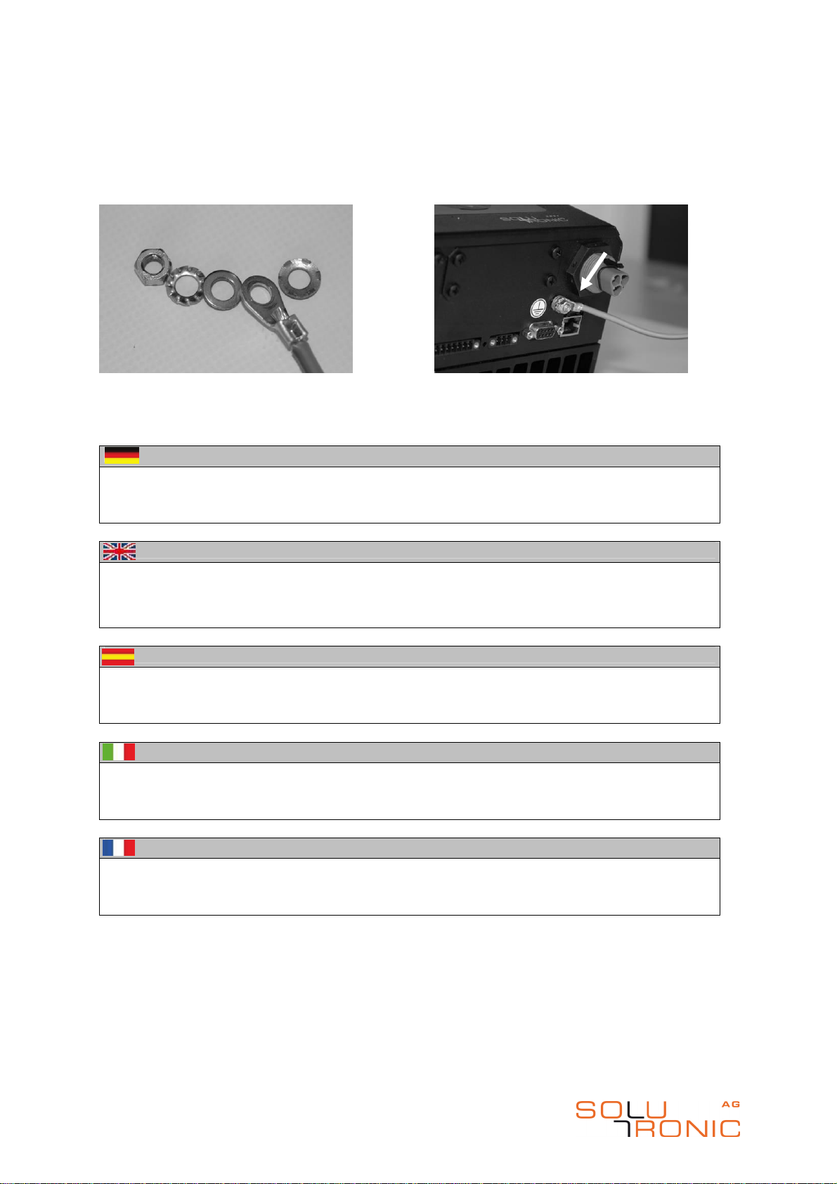
Schritt 11-12
Erdung (zweiter Schutzleiteranschluss). Die Norm EN 50178 fordert einen zweiten, festen
Schutzleiteranschluss. Führen Sie das Kabel in eine Potentialausgleichsschiene, die mit
dem Schutzleiter verbunden ist. Näheres siehe Installationsanleitung.
Step 11-12
Grounding (second protective ground (PE) connection). According to EN 50178 a second,
fixed PE connection is required. Connect the ground cable to an equipotential bonding
strip that is connected to the PE conductor. For more information, see the Installation
Instructions manual.
Paso 11-12
La puesta a tierra (segundo borne de puesta a tierra). EN 50178 requiere un segundo
borne de puesta a tierra fijo.
Passo 11-12
Massa (secondo motivo del filo di collegamento). La norma EN 50178 richiede un secondo
conduttore di terra fisso di protezione. Il cavo che è collegato alla terra va inserito in un
binario di compensazione. Di seguito vedere le istruzioni d’installazione.
Pas 11-12
La mise à terre (deuxième raccordement du conducteur de protection). EN 50178 exige un
deuxième raccordement. Connecter le câble de mise à terre au circuit de mise à terre.
(Pour les détails voir manuel d’installation).

SP25-55_Kurzinstallationsanleitung_DEFSI_A6_2012-01-12 11/23
Kurzanleitung SP 25-55, Brief Installation Manual SP 25-55,
Instrucciones de instalación SP 25-55, Brevi istruzioni per
l´installazione SP 25-55, Instructions d´installation série SP 25-55
4.10 Anschließen des 3-adrigen Netzsteckers
Grid connection with 3-wire power plug
Connectar el enchufe de 3 hilos
Collegamento alla spina a 3 fili
Connecter la fiche de contact de 3 fils
Schritt 13
Der Netzanschluss erfolgt 3-adrig (N, L, PE). Wenn Sie das Netzanschlusskabel durch die
Überwurfmutter durchgezogen haben, schließen Sie das Netzkabel wie im Bild an die
Anschlussklemme an.
Step 13
The grid connection has 3 wires (N, L and PE). After pulling the grid connection cable through the
cap nut, connect it to the terminals as shown.
Paso 13
La conexión a la red tiene lugar a través de 3 hilos (N, L, PE). Cuando haya metido el cable de red
por la tuerca tapón conecte el cable de red al borne de conexión como se muestra a continuación.
Passo 13
Il collegamento alla rete ha 3 fili (N, L, PE). Una volta infilato il cavo di collegamento attraverso la
ghiera, connettere il cavo di rete ai terminali come in foto.
Pas 13
La connection au réseau est assurée par 3 fils électriques (N, L, PE). Connecter le câble dans la
prise (voir image) aussitôt que le câble électrique est introduit dans la fixation.
PE=gelb-grün /
yellow-green /
ammarillo-verde /
giallo-verde /
jaune
-
verte
L=grau / grey / gris
/ grigio / grise
N=blau / blue /
A
zul
/
blu
/
bleu

SP25-55_Kurzinstallationsanleitung_DEFSI_A6_2012-01-12 12/23
Kurzanleitung SP 25-55, Brief Installation Manual SP 25-55,
Instrucciones de instalación SP 25-55, Brevi istruzioni per
l´installazione SP 25-55, Instructions d´installation série SP 25-55
4.11 AC-Anschlüsse 4.12 DC-Anschluss
AC connector DC connector
Conector AC Conector DC
AC nella presa DC nella presa
Connecter AC Connecter DC
4.13 Anschalten
Power on
Encender
Accendere
Enclencher
Schritt 15-17
Stecken Sie den AC-Stecker und die DC-Stecker ein und überprüfen Sie, ob der AC-Stecker und die
DC-Stecker richtig eingerastet sind. Anschließend schalten Sie den Wechselrichter mit dem DC-
Freischalter ein.
Step 15-17
Plug in the AC connector and the DC connectors and make sure that they are properly locked in
position. Then switch on the inverter by means of the DC isolator.
Paso 15-17
Enclavamiento del conector AC. Enclavamiento del conector DC. Encender inversor.
Passo 15-17
Inserire la spina AC nella presa, Inserire la spina DC nella presa. Accendere l’inverter.
Pas 15-17
Enfiler les connecteurs AC et DC. Contrôler si les connecteurs AC et DC sont correctement
encliqueter. Ensuite enclencher l’onduleur.
Warnung/Caution/Aviso de
advertencia/
Avvertenza/Avertissement
Bitte Polung beachten!
Please pay attention to the polarity!
Comprobarse que la polaridad sea
correcta!
Verificare la coretta polarità!
Vérifiez la bonne polarité!
vorne/front/a
delante/davant/à l’avant
+
hinten/back/detrás/dietro/à
l’arriere
-

SP25-55_Kurzinstallationsanleitung_DEFSI_A6_2012-01-12 13/23
Kurzanleitung SP 25-55, Brief Installation Manual SP 25-55,
Instrucciones de instalación SP 25-55, Brevi istruzioni per
l´installazione SP 25-55, Instructions d´installation série SP 25-55
5. Setup Menü/Setup menu/Menu de paramétrage/Menu du setup/
Menú de configuración
5.1 Setup-Menü
Dieser SOLPLUS Wechselrichter ist mit einem Setup-Menü ausgestattet.
Hinweis
Beim Start des Gerätes muss das Setup-Menü einmal durchlaufen
werden.
Displaybedienung
Bedeutungen der Tasten :
Voreinstellungen
Schritt 1: Sprache
Schritt 2: länderspezifische Einstellung
Die aktuell möglichen Ländereinstellungen und die hinterlegte Konfiguration entnehmen Sie bitte dem
Beiblatt.
Auf
Ab
Links
Rechts
OK/bestätigen
OK
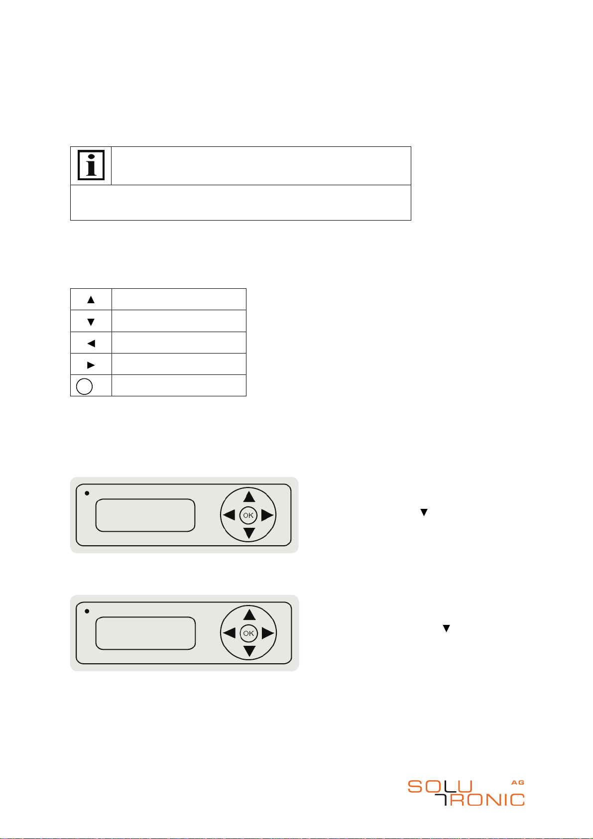
Select language
[ deutsch ]
english
cestina
Nach dem ersten Starten des SOLPLUS
Wechselrichters ist die Sprache
auszuwählen.
Um durch das Sprachmenü zu blättern,
drücken Sie „ “. Anschließend die
gewünschte Sprache mit der Taste „OK“
auswählen.
Länderspezifische Einstellungen
[ de (VDE0126-1-1) ]
ch (VDE0126-1-1
at (öNORM E2750)
Die länderspezifische Einstellung laut
Bezeichnung auf dem Display einstellen.
Durch drücken der Taste „ “ können Sie
durch die lände
rspezifischen Einstellungen
blättern. Durch drücken der Taste „OK“
auswählen.
SP25-55_Kurzinstallationsanleitung_DEFSI_A6_2012-01-12 14/23
Kurzanleitung SP 25-55, Brief Installation Manual SP 25-55,
Instrucciones de instalación SP 25-55, Brevi istruzioni per
l´installazione SP 25-55, Instructions d´installation série SP 25-55
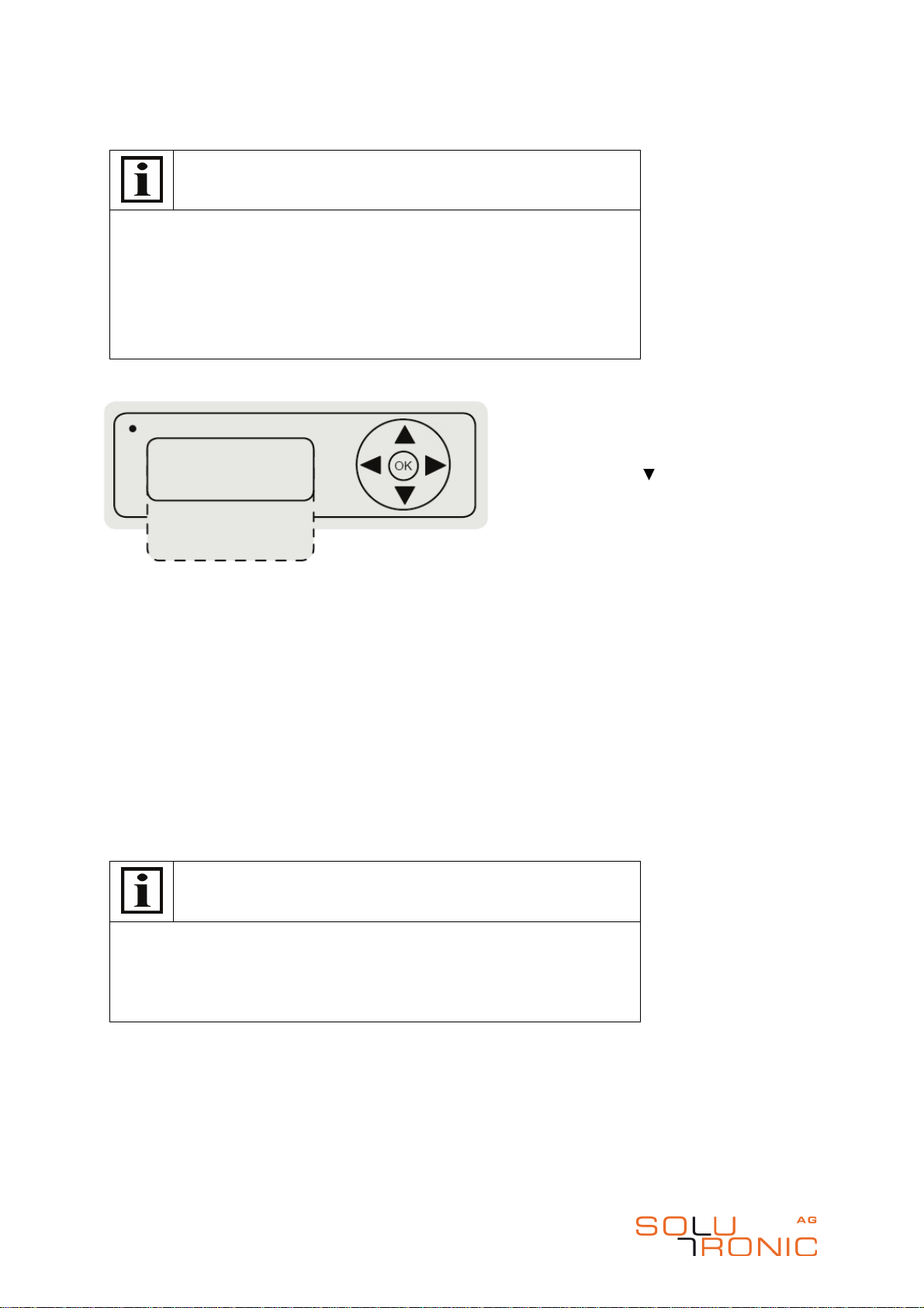
Schritt 3: Voreinstellungen
Hinweis
•
Nach den Sprach- und länderspezifischen Einstellungen besteht
die Möglichkeit das Setup-Menü zu beenden.
•
Im Weiteren können Sie die Uhrzeit und das Datum überprüfen und
die wichtigsten Einstellungen zur Ertragskontrolle und
Kommunikation vornehmen.
•
Am Ende besteht die Möglichkeit, die bereits gewählte Sprach- /
Ländereinstellung zu verändern.
Erweiterte Voreinstellungen:
•
Uhrzeit: Einstellung von der Uhrzeit. Einheit: HH:MM:SS
•
Datum: Einstellung vom Datum. Einheit: DD.MM.YYYY
•
Ertragskontrolle: Eingabe der DC-Nennleistungen pro String / Wechselrichter und Eingabe
des Vergütungssatzes möglich.
•
Kommunikation: Sie haben die Option, die Kommunikationsdaten vorab wie z. B. die IP-
Adresse von Ihrem bestehenden Netzwerk oder die Wechselrichteradresse für Ihren Master-
Slave Datenverbund einzutragen.
•
Sprache: Sie haben die Möglichkeit, die bereits gewählte Spracheinstellung zu verändern.
•
Ländercode: Sie haben die Möglichkeit, den bereits gewählten Ländercode zu verändern.
Tipp
Eine einwandfreie Anlagenüberwachung mit Protokollierung ist nur dann
gewährleistet, wenn Datum und Uhrzeit richtig eingestellt sind.
Für eine sinnvolle spezifische Ertragskontrolle ist die Eingabe der DC-
Nennleistung erforderlich.
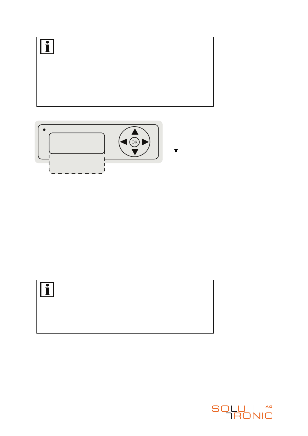
Voreinstellungen
SETUP beenden
12:01:56
18.12.2025
Ertragskontrolle
Kommunikation
Sprache
Ländercode
Um das Setup-Menü zu beenden
drücken Sie die Taste „
OK“. Um weitere
Einstellungen vorzunehmen, blättern
Sie mit der Taste „ “ weiter. Wählen
Sie mit „OK“ die gewünschte
Voreinstellung aus.
SP25-55_Kurzinstallationsanleitung_DEFSI_A6_2012-01-12 15/23
Kurzanleitung SP 25-55, Brief Installation Manual SP 25-55,
Instrucciones de instalación SP 25-55, Brevi istruzioni per
l´installazione SP 25-55, Instructions d´installation série SP 25-55
5.2 Setup Menu
This SOLPLUS inverter is supplied with a Setup menu.
Note
You must run through the entire Setup menu when starting the inverter for
the first time.
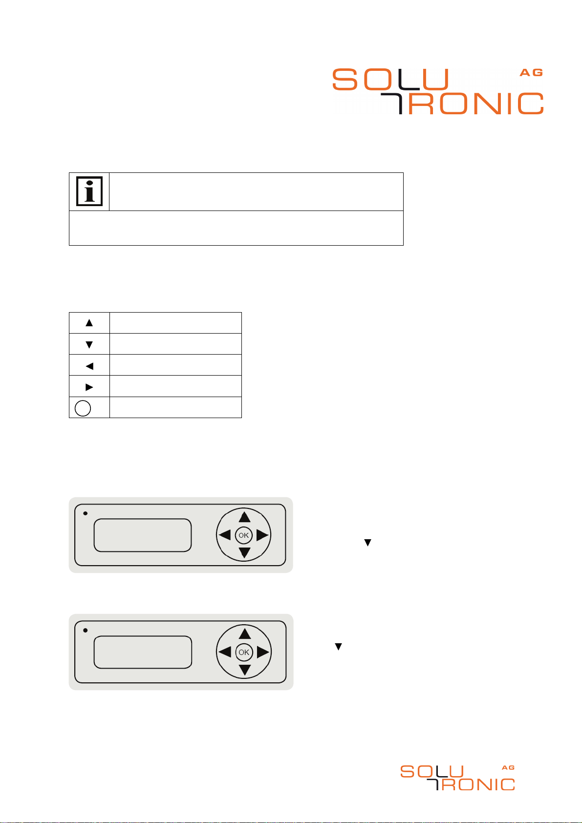
Using The Display
What the buttons do:
Default Settings
Step 1: Language
Step 2: Country-specific setting
* Please refer to the enclosed supplementary sheet for the country-specific settings currently available.
Up
Down
Left
Right
OK / Confirm
OK
Select Language
[ deutsch ]
english
cestina
Country
-
specific Settings
[ de (VDE0126-1-1) ]
ch (VDE0126-1-1
at (öNORM E2750)
Set the country-specific setting (country
code) as indicated on the display. Press
the " " button to scroll through the
options. Press the "OK" button to select
the setting you want.
After starting the SOLPLUS inverter for the
first time, select the language you want to
use.
Press the " " button to scroll through the
language menu. Then select the language
you want by pressing the "OK" button.
SP25-55_Kurzinstallationsanleitung_DEFSI_A6_2012-01-12 16/23
Kurzanleitung SP 25-55, Brief Installation Manual SP 25-55,
Instrucciones de instalación SP 25-55, Brevi istruzioni per
l´installazione SP 25-55, Instructions d´installation série SP 25-55
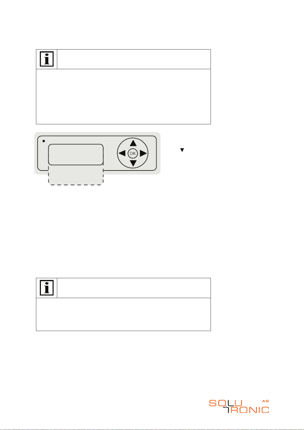
Step 3: Default Settings
Note
•
You have the option of exiting the Setup menu after you have
selected the language and country-specific setting.
•
The subsequent steps enable you to check the time and date
settings and to enter the main settings relating to yield monitoring
and communication.
•
At the end of the Setup menu, you are given the opportunity to
change the language and country-specific setting you have already
selected.
Advanced Default Settings
•
Time: To set the time. Unit: HH:MM:SS
•
Date: To set the date. Unit: DD.MM.YYYY
•
Yield monitoring: To enter the nominal DC outputs per string/inverter and to enter the feed-in
tariff.
•
Communication: To enter the communication settings, such as the IP address of your existing
network or the inverter address of your master-slave network.
•
Language: To change the language setting you have already selected.
•
Country code: To change the country code you have already selected.
Tip
Your installation can only be monitored and its data logged properly if the
time and date settings are correct.
If the yield monitoring data for your PV installation is to be meaningful, you
must enter the nominal DC outputs.
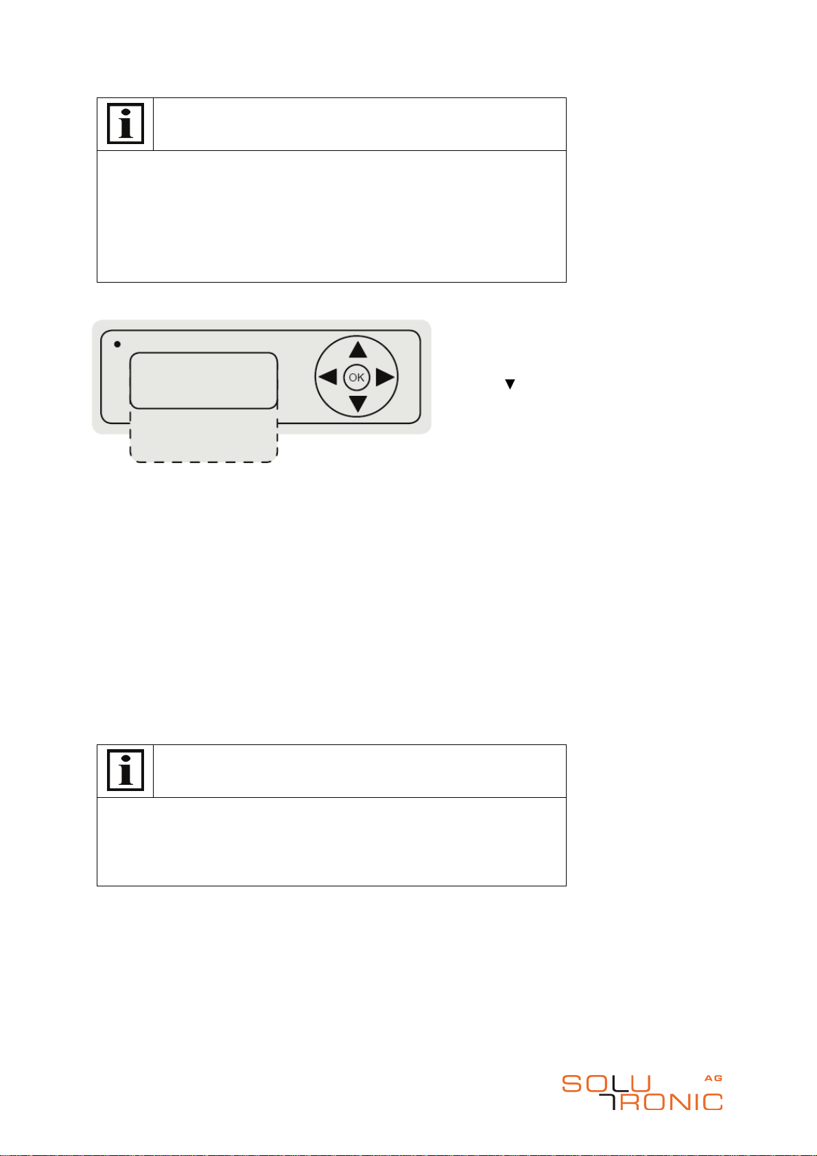
Default Settings
Exit SETUP
12:01:56
18.12.2025
Yield Monitoring
Communication
Language
Country Code
To exit the Setup menu, press the "OK"
button. To make further settings, press
the " " button to scroll through the
options. Press the "OK" button to selec
t
the setting you want.
SP25-55_Kurzinstallationsanleitung_DEFSI_A6_2012-01-12 17/23
Kurzanleitung SP 25-55, Brief Installation Manual SP 25-55,
Instrucciones de instalación SP 25-55, Brevi istruzioni per
l´installazione SP 25-55, Instructions d´installation série SP 25-55
5.3 Menu de paramétrage
Cette onduleur SOLPLUS est équipé d’un menu de paramétrage.
Consigne
Lors du démarrage de l’appareil, le menu de paramétrage doit être
parcouru.
Commande d’affichage
Significations des touches :
Pré-réglages
Etape 1: Langue
Etape 2: Réglage spécifique aux pays
Veuillez extraire du supplément les réglages pays actuels possibles.
Etape 3: Pré-réglages
En haut
En bas
A droite
A gauche
OK/confirmer
OK
Sélectionner la langue
[ allemand ]
anglais
cestina
Une fois que vous avez démarré l’onduleur
SOLPLUS, vous devez sélectionner la
langue. Pour faire défiler le menu des
langues, appuyez sur „ “. Sélectionnez
alors la langue souhaitée en appuyant sur
„OK“.
Réglages spécifiques aux pays
[ Agne (VDE0126-1-1) ]
Suisse (VDE0126-1-1
Autr (öNORM E2750)
Paramétrez le réglage spécifi
que aux pays
selon le message apparaissant à l‘écran.
En appuyant sur la touche „ “ vous
pouvez naviguer dans le menu de réglage
spécifique aux pays. Sélectionnez en
appuyant sur la touche „OK“.
SP25-55_Kurzinstallationsanleitung_DEFSI_A6_2012-01-12 18/23
Kurzanleitung SP 25-55, Brief Installation Manual SP 25-55,
Instrucciones de instalación SP 25-55, Brevi istruzioni per
l´installazione SP 25-55, Instructions d´installation série SP 25-55
Consigne
•
Une fois les réglages langue et spécifiques aux pays effectués,
vous pouvez quitter le menu de paramétrage.
•
Vous pouvez ensuite vérifier l’heure et la date et effectuer les
réglages importants au contrôle de rendement et à la
communication.
•
A la fin, vous avez la possibilité de modifier le réglage langue/pays
déjà sélectionné.
Pré-réglages élargis:
•
Heure: Réglage de l‘heure. Unité: HH:MM:SS
•
Date: Réglage de la date. Unité: JJ.MM.AAAA
•
Contrôle du rendement: Saisie des puissances nominales CC par String / onduleur et saisie
des taux de traitement possible.
•
Communication: Vous avez l’option de préalablement rentrer les données de communication,
comme par exemple l’adresse IP de votre réseau actuel ou l’adresse de l’onduleur pour votre
liaison de données Maître-Esclave.
•
Langue: Vous avez la possibilité de modifier le réglage de la langue déjà sélectionnée.
•
Code pays: Vous avez la possibilité de modifier le code pays déjà sélectionné.
Astuce
Un contrôle d’installation irréprochable avec enregistrement du protocole
n’est possible que si la date et l’heure sont correctement réglés.
Pour un contrôle de rendement spécifique et sensé, il est nécessaire de
d‘entrer la puissance nominale CC.
Pré-réglages
Terminer le PARAMETRAGE
12:01:56
18.12.2025
Contrôle de rendement
Communication
Langue
Ländercode
Pour quitter le menu de paramétrage,
appuyez sur la touche „OK“. Pour
effectuer d’autres régla
ges, continuez à
faire défiler le menu grâce à la touche
„ “. Sélectionnez le pré-réglage
souhaité par „OK“.

SP25-55_Kurzinstallationsanleitung_DEFSI_A6_2012-01-12 19/23
Kurzanleitung SP 25-55, Brief Installation Manual SP 25-55,
Instrucciones de instalación SP 25-55, Brevi istruzioni per
l´installazione SP 25-55, Instructions d´installation série SP 25-55
5.4 Menu du
setup
Questo inverter SOLPLUS è dotato di un menu di setup.
Nota
Quando si avvia l'apparecchio, scorrere il menu di setup.
Uso del display
Significato dei tasti:
Impostazioni predefinite
Passaggio 1: Lingua
Passaggio 2: impostazione specifica per paese
*Le impostazioni del paese possibili sono indicate nella scheda allegata.
Passaggio 3: Impostazioni predefinite
Su
Giù
Sinistra
Destra
OK/confermare
OK
Select language
[ deutsch ]
english
cestina
Dopo il primo avvio dell'inverter SOLPLUS,
selezionare la lingua.
Per sfogliare il menu delle lingue, premere
„ “. Successivamente selezionare la lingua
con il tasto „OK“.
Impostazioni specifiche per paese
[ de (VDE0126-1-1) ]
ch (VDE0126-1-1
at (öNORM E2750)
Impostare l'impostazione specifica per
paese secondo il messaggio sul display.
Premendo il tasto „ “ è possibile sfogliare
le impostazioni specifiche per paese.
Selezionare premendo il tasto „OK“.
SP25-55_Kurzinstallationsanleitung_DEFSI_A6_2012-01-12 20/23
Kurzanleitung SP 25-55, Brief Installation Manual SP 25-55,
Instrucciones de instalación SP 25-55, Brevi istruzioni per
l´installazione SP 25-55, Instructions d´installation série SP 25-55
Nota
•
Dopo le impostazioni della lingua e quelle specifiche per paese è
possibile chiudere il menu di setup.
•
Successivamente è possibile controllare l'ora e la data ed
effettuare le principali impostazioni di controllo del rendimento e di
comunicazione.
•
Infine è possibile modificare l'impostazione lingua/paese già
selezionata.
Impostazioni predefinite ampliate:
•
Ora: impostazione dell'ora. Unità: HH:MM:SS
•
Data: Impostazione della data. Unità: DD.MM.YYYY
•
Controllo del rendimento: Inserimento delle potenze nominali DC per stringa/inverter e
inserimento del tasso di remunerazione.
•
Comunicazione: Esiste l'opzione di preinserimento dei dati di comunicazione, come ad es.
indirizzo IP della propria rete esistente o l'indirizzo dell'inverter per la propria rete dati master-
slave.
•
Lingua: è possibile modificare l'impostazione della lingua già selezionata.
•
Codice paese: è possibile modificare il codice paese già selezionato.
Suggerimento
Un monitoraggio perfetto dell'impianto è possibile solo se data e ora sono
impostati correttamente.
Per un opportuno controllo del rendimento specifico è necessario inserire
la potenza nominale DC.
Impostazioni predefinite
Uscire da SETUP
12:01:56
18.12.2025
Controllo del rendimento
Comunicazione
Lingua
Codice paese
Per terminare il menu di setup,
premere
il tasto „OK“. Per effettuare altre
impostazioni, continuare a sfogliare con
il tasto „ “. Selezionare con „OK“
l'impostazione predefinita desiderata.
Table of contents
Popular Inverter manuals by other brands


Renogy
Renogy Wanderer 30A manual

Lux Power Technology
Lux Power Technology SNA3000 WPV user manual

VOLTCRAFT
VOLTCRAFT PI 100-12 USB operating instructions

Energy
Energy zeroCO2 large RHI-3P5K-HVES-5G Operation manual

Schumacher Electric
Schumacher Electric XI41DU owner's manual

Chelion
Chelion iHome-INV3K-6K-L1h02 user manual