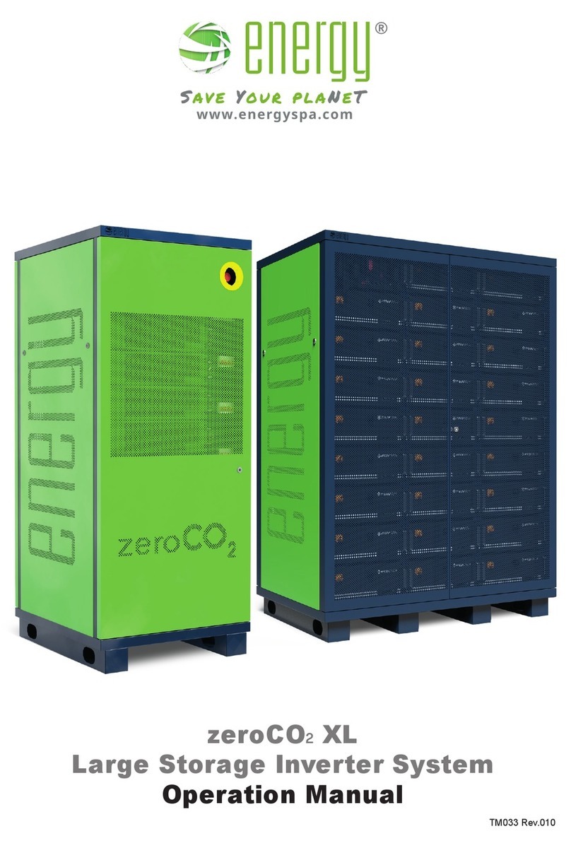
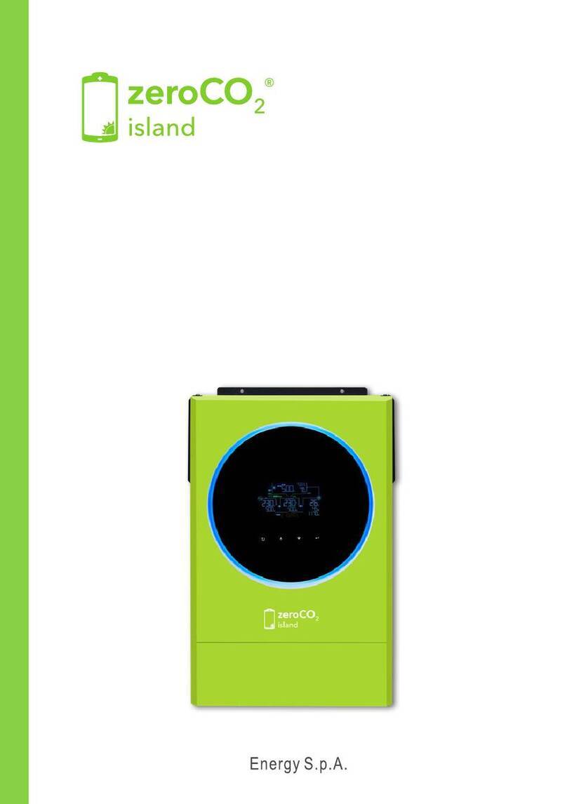
Energy zeroCO2 large RHI-3P5K-HVES-5G User manual

This manual refer to
zeroCOlarge (5-10)K inverter models:
RHI-3P5K-HVES-5G
RHI-3P6K-HVES-5G
RHI-3P8K-HVES-5G
RHI-3P10K-HVES-5G
Three-phase Hybrid Inverter - 5G
Operation Manual
TM015 Rev.003

. 2 .
Table of Content
Quick Guide ................................................................................................... 4
Wiring diagrams ........................................................................................... 6
1. Introduction ................................................................................................... 8
1.1 Product Description................................................................................ 8
1.2 Packing list ............................................................................................. 9
2. Safety & Warning..........................................................................................10
2.1 Safety ....................................................................................................10
2.2 General Safety Instructions ..................................................................10
2.3 Usage warnings ....................................................................................12
3. Overview .......................................................................................................13
3.1 Screen...................................................................................................13
3.2 Keypad ..................................................................................................13
3.3 Terminal Connection .............................................................................13
4. Installation ....................................................................................................14
4.1 Select a Location for the Inverter..........................................................14
4.2 Equipment list to be used......................................................................16
4.3 Mounting the Inverter ............................................................................17
4.4 PV Input Terminal Assembly .................................................................18
4.5 Battery Terminal Components ..............................................................19
4.6 Assembling the AC Connector..............................................................21
4.7 Meter Installation.................................................................................. 23
4.7.1 Three-Phase Meter Installation (installation with CT) ..........24
4.7.2 Three-Phase Meter Installation (direct insertion) .................26
4.8 Communication Cable Assembly......................................................... 28
4.9 External ground connection ................................................................. 30
4.10 Preparation of Commissioning............................................................. 30
4.11 Commissioning procedure ................................................................... 30
4.12 Inverter monitoring connection .............................................................31

. 3 .
5. Operation ..................................................................................................... 32
5.1 LED indicators...................................................................................... 32
5.2 Main Menu ........................................................................................... 33
5.3 Information ........................................................................................... 33
5.4 Settings .................................................................................................37
5.4.1 Set Time/Date.......................................................................37
5.4.2 Set Address .......................................................................... 37
5.5 Advanced Information .......................................................................... 38
5.5.1 Alarm Message.....................................................................38
5.5.2 Warning Message.................................................................38
5.5.3 Running Status .....................................................................39
5.5.4 Communication Data ............................................................40
5.5.5 YieldProle...........................................................................40
5.5.6 Inspection .............................................................................40
5.6 Advanced Settings ................................................................................41
5.6.1 Select Standard .................................................................... 41
5.6.2 Grid Switches........................................................................42
5.6.3 Battery Control...................................................................... 42
5.6.3.1 Battery Select .......................................................................42
5.6.4 Backup Control .....................................................................43
5.6.4.1 Backup ON/OFF ...................................................................43
5.6.4.2 Backup Settings....................................................................43
5.6.5 Storage Energy Set...............................................................43
5.6.5.1 Meter Set ..............................................................................43
5.6.5.2 STG Mode Select..................................................................45
5.6.6 STD Mode Settings............................................................... 47
5.6.7 Software Update ................................................................... 47
5.6.8 Export Power Set..................................................................48
5.6.8.1 EPM ON/OFF........................................................................48
5.6.8.2 BackowPower ....................................................................48
5.6.8.3 FailSafe ON/OFF (not used in Italy)......................................48
5.6.9 Reset Password....................................................................48
5.6.10 RESTART HMI......................................................................49
5.6.11 Self Test CEI 0-21.................................................................49
5.6.12 Compensation Set ................................................................49
5.7 Special Settings ................................................................................... 50
5.7.1 Enable AFCI function............................................................50
5.7.2 EPS Mode.............................................................................50
6. Maintenance..................................................................................................51
6.1 Cleaning ................................................................................................51
7. Troubleshooting .......................................................................................... 52
7.1 Error messages and solutions ............................................................. 52
8. Specications.............................................................................................. 56
8.1 Technical data ...................................................................................... 56
9. Appendix ...................................................................................................... 60
9.1 EPS Box Installation............................................................................. 60
9.2 Grid standard selection guide .............................................................. 62

. 4 .
Quick Guide
First Start
After making all the connections as per the diagrams provided, start the inverter according to
the following instructions:
• Power the inverter on the AC side (grid connection).
• Turn the DC switch of the strings to the “ON” position (inverter side).
• Wait until inverter display is on (may occur 30”)
• Turn on the batteries. The communication between the inverter and the batteries will take
place in about 300".
Batteryconguration
• Go to Main Menu.
• Go to ADVANCED SETTINGS.
• Type the password 0010 (DOWN -DOWN – UP – ENTER).
• Go to BATTERY CONTROL.
• Go to BATTERY SELECT.
• Select PYLON LV.
• OverDischarge SOC: 20%.
• ForceCharge SOC: 10% (PS: set FORCECHG current to 10A or 500W).
Meterconguration
• Go to Main Menu.
• Go to ADVANCED SETTINGS.
• Type the password 0010 (DOWN -DOWN – UP – ENTER).
• Go to STORAGE ENERGY SET.
• Go to METER SET.
• Select METER SELECT.
• Select EASTRON 3PH METER (Choice valid for both models: SDM630 - SDM630MCT).
Selfuseconguration
• Go to Main Menu.
• Go to ADVANCED SETTINGS.
• Type the password 0010 (DOWN -DOWN – UP – ENTER).
• Go to STORAGE ENERGY SET.
• Go to STORAGE MODE SELECT.
• Select SELF USE then ENTER.
• Select ON.
• Charging from grid: ALLOW.

. 5 .
Self Test CEI-0-21
• Go to Main Menu.
• Go to ADVANCED SETTINGS.
• Type the password 0010 (DOWN -DOWN – UP – ENTER).
• Go to SELF TEST CEI 0 21.
• Go to COMPLETE TEST.
• Select YES and wait for the threshold analysis to complete.
• Results are available from TEST REPORT (same menu).
Lmt by Epm mode
• Go to Main Menu.
• Go to ADVANCED SETTINGS.
• Type the password 0010 (DOWN -DOWN – UP – ENTER).
• Go to EXPORT POWER SET.
• Set On/Off →ON.
• SetBackowpower→+0000W (Maximum output power to the meter).
• Set Failsafe →OFF.
To deactivate Lmt by Epm mode set On/Off →OFF.
WiFiConguration(site/appSolisCloud)
ThewicongurationisimportanttofullyvalidatethezeroCOlarge product warranty.
Thewarrantycanbeextendedfromvetotenyearsonlyandexclusivelybyregisteringthe
product in the online portal: www.soliscloud.com.
Forcongurationinformation,refertotheWiFiguideforzeroCO2availableonthe
www.energysynt.com website.

. 6 .
Wiring diagrams
Thefollowingtableshowstheexpectedcongurations.
By clicking on the link in the DIAGRAM column you can download the corresponding wiring diagram.
INVERTER METER CT EPM EPS BOX SCHEMA
Proprietà riservata. Riproduzione vietata ai temrini di legge-Copyright/Reserved proprietorship. Forbidden reproduction to the terms of law-Copyright. M001-Rev.01 - 13/12/2016
LOAD BACKUP GRID
LOAD BACKUP GRID
Proprietà riservata. Riproduzione vietata ai temrini di legge-Copyright/Reserved proprietorship. Forbidden reproduction to the terms of law-Copyright. M001-Rev.01 - 13/12/2016
LOAD BACKUP GRID
LOAD BACKUP GRID
Proprietà riservata. Riproduzione vietata ai temrini di legge-Copyright/Reserved proprietorship. Forbidden reproduction to the terms of law-Copyright. M001-Rev.01 - 13/12/2016
LOAD BACKUP GRID
LOAD BACKUP GRID
Proprietà riservata. Riproduzione vietata ai temrini di legge-Copyright/Reserved proprietorship. Forbidden reproduction to the terms of law-Copyright. M001-Rev.01 - 13/12/2016
LOAD BACKUP GRID
LOAD BACKUP GRID
Proprietà riservata. Riproduzione vietata ai temrini di legge-Copyright/Reserved proprietorship. Forbidden reproduction to the terms of law-Copyright. M001-Rev.01 - 13/12/2016
LOAD BACKUP GRID
LOAD BACKUP GRID
Meter
SDM630MCT
WD047
Proprietà riservata. Riproduzione vietata ai temrini di legge-Copyright/Reserved proprietorship. Forbidden reproduction to the terms of law-Copyright. M001-Rev.01 - 13/12/2016
LOAD BACKUP GRID
LOAD BACKUP GRID
Proprietà riservata. Riproduzione vietata ai temrini di legge-Copyright/Reserved proprietorship. Forbidden reproduction to the terms of law-Copyright. M001-Rev.01 - 13/12/2016
LOAD BACKUP GRID
LOAD BACKUP GRID
Proprietà riservata. Riproduzione vietata ai temrini di legge-Copyright/Reserved proprietorship. Forbidden reproduction to the terms of law-Copyright. M001-Rev.01 - 13/12/2016
LOAD BACKUP GRID
LOAD BACKUP GRID
Proprietà riservata. Riproduzione vietata ai temrini di legge-Copyright/Reserved proprietorship. Forbidden reproduction to the terms of law-Copyright. M001-Rev.01 - 13/12/2016
LOAD BACKUP GRID
LOAD BACKUP GRID
Proprietà riservata. Riproduzione vietata ai temrini di legge-Copyright/Reserved proprietorship. Forbidden reproduction to the terms of law-Copyright. M001-Rev.01 - 13/12/2016
LOAD BACKUP GRID
LOAD BACKUP GRID
Meter
SDM630
WD046
Proprietà riservata. Riproduzione vietata ai temrini di legge-Copyright/Reserved proprietorship. Forbidden reproduction to the terms of law-Copyright. M001-Rev.01 - 13/12/2016
LOAD BACKUP GRID
LOAD BACKUP GRID
Proprietà riservata. Riproduzione vietata ai temrini di legge-Copyright/Reserved proprietorship. Forbidden reproduction to the terms of law-Copyright. M001-Rev.01 - 13/12/2016
LOAD BACKUP GRID
LOAD BACKUP GRID
Proprietà riservata. Riproduzione vietata ai temrini di legge-Copyright/Reserved proprietorship. Forbidden reproduction to the terms of law-Copyright. M001-Rev.01 - 13/12/2016
LOAD BACKUP GRID
LOAD BACKUP GRID
Proprietà riservata. Riproduzione vietata ai temrini di legge-Copyright/Reserved proprietorship. Forbidden reproduction to the terms of law-Copyright. M001-Rev.01 - 13/12/2016
LOAD BACKUP GRID
LOAD BACKUP GRID
Proprietà riservata. Riproduzione vietata ai temrini di legge-Copyright/Reserved proprietorship. Forbidden reproduction to the terms of law-Copyright. M001-Rev.01 - 13/12/2016
LOAD BACKUP GRID
LOAD BACKUP GRID
No Meter
WD085
Proprietà riservata. Riproduzione vietata ai temrini di legge-Copyright/Reserved proprietorship. Forbidden reproduction to the terms of law-Copyright. M001-Rev.01 - 13/12/2016
LOAD BACKUP GRID
LOAD BACKUP GRID
Proprietà riservata. Riproduzione vietata ai temrini di legge-Copyright/Reserved proprietorship. Forbidden reproduction to the terms of law-Copyright. M001-Rev.01 - 13/12/2016
LOAD BACKUP GRID
LOAD BACKUP GRID
Proprietà riservata. Riproduzione vietata ai temrini di legge-Copyright/Reserved proprietorship. Forbidden reproduction to the terms of law-Copyright. M001-Rev.01 - 13/12/2016
LOAD BACKUP GRID
LOAD BACKUP GRID
Proprietà riservata. Riproduzione vietata ai temrini di legge-Copyright/Reserved proprietorship. Forbidden reproduction to the terms of law-Copyright. M001-Rev.01 - 13/12/2016
LOAD BACKUP GRID
LOAD BACKUP GRID
Proprietà riservata. Riproduzione vietata ai temrini di legge-Copyright/Reserved proprietorship. Forbidden reproduction to the terms of law-Copyright. M001-Rev.01 - 13/12/2016
LOAD BACKUP GRID
LOAD BACKUP GRID
Meter
SDM630MCT
WD093
Proprietà riservata. Riproduzione vietata ai temrini di legge-Copyright/Reserved proprietorship. Forbidden reproduction to the terms of law-Copyright. M001-Rev.01 - 13/12/2016
LOAD BACKUP GRID
LOAD BACKUP GRID
Proprietà riservata. Riproduzione vietata ai temrini di legge-Copyright/Reserved proprietorship. Forbidden reproduction to the terms of law-Copyright. M001-Rev.01 - 13/12/2016
LOAD BACKUP GRID
LOAD BACKUP GRID
Proprietà riservata. Riproduzione vietata ai temrini di legge-Copyright/Reserved proprietorship. Forbidden reproduction to the terms of law-Copyright. M001-Rev.01 - 13/12/2016
LOAD BACKUP GRID
LOAD BACKUP GRID
Proprietà riservata. Riproduzione vietata ai temrini di legge-Copyright/Reserved proprietorship. Forbidden reproduction to the terms of law-Copyright. M001-Rev.01 - 13/12/2016
LOAD BACKUP GRID
LOAD BACKUP GRID
Proprietà riservata. Riproduzione vietata ai temrini di legge-Copyright/Reserved proprietorship. Forbidden reproduction to the terms of law-Copyright. M001-Rev.01 - 13/12/2016
LOAD BACKUP GRID
LOAD BACKUP GRID
Meter
SDM630
WD110

. 7 .

. 8 .
1. Introduction
1.1 Product Description
zeroCOlarge (5-10)K Series is designed for residential hybrid systems, which can work with
batteries to optimize self-consumption.
Keypad
DC Switch
LED Indicators
Display
Figura 1 - Front side view
Proprietà riservata. Riproduzione vietata ai temrini di legge-Copyright/Reserved proprietorship. Forbidden reproduction to the terms of law-Copyright. M001-Rev.01 - 13/12/2016
XX
Figura 2 - Bottom side view

. 9 .
1. Introduction
1.2 Packing list
Please ensure that the following items are included in the packaging with your machine.
Proprietà riservata. Riproduzione vietata ai temrini di legge-Copyright/Reserved proprietorship. Forbidden reproduction to the terms of law-Copyright. M001-Rev.01 - 13/12/2016
Inverter mounting bracket Fixing screws AC—GRID Terminal
AC—BACKUP Terminal
RS485 Meter Cable
Wi-Fi Antenna ×1 User Manual ×1 Antenna and Wi-Fi module
Eastron Meter CT
RJ45 Connector
Use both connectors
for UK and AU
If present, to be taken as a
replacement of a part of the
Wi-Fi module
DC (—) Connector Battery Connector
Red
DC ( ) Connector

. 10 .
2. Safety & Warning
2.1 Safety
The following types of safety instructions and general information appear in this document as
described below.
DANGER
“Danger”indicates a hazardous situation which if not avoided, will result in death or
serious injury.
WARNING
“Warning” indicates a hazardous situation which if not avoided, could result in death or
serious injury.
CAUTION
“Caution” indicates a hazardous situation which if not avoided, could result in minor or
moderate injury.
NOTE
“Note” provides tips that are valuable for the optimal operation of your product.
2.2 General Safety Instructions
WARNING
Only devices in compliance with SELV (EN 69050) may be connected to the RS485
and USB interfaces.
WARNING
Please don’t connect PV array positive (+) or negative (-) to ground, it could cause
serious damage to the inverter.
WARNING
Electrical installations must be done in accordance with the local and national
electrical safety standards.
WARNING
Do not touch any inner live parts until 5 minutes after disconnection from the
utility grid and the PV input.
WARNING
Toreducetheriskofre,over-currentprotectivedevices(OCPD)arerequired
for circuits connected to the inverter. The DC OCPD shall be installed per local
requirements. All photovoltaic source and output circuit conductors shall have isolators
that comply with the NEC Article 690, Part II. All zeroCO2large (5-10)K inverters
feature an integrated DC switch..

. 11 .
2. Safety & Warning
CAUTION
Risk of electric shock, do not remove cover. There is no user serviceable parts inside,
referservicingtoqualiedandaccreditedservicetechnicians.
CAUTION
The PV array supplies a DC voltage
when they are exposed to sunlight.
CAUTION
Risk of electric shock from energy stored in capacitors of the inverter, do not remove
cover for 5 minutes after disconnecting all power sources (service technician only).
Warranty may be voided if the cover is removed without authorization..
CAUTION
The surface temperature of the inverter can reach up to 75°C (167 F). To avoid risk
of burns, do not touch the surface of the inverter while it’s operating. Inverter must be
installed out of the reach of children.
NOTE
PV module used with inverter must have an IEC 61730 Class A rating.
WARNING
Operations below must be accomplished by licensed technician or zeroCO2large (5-
10)K authorized person.
WARNING
Operator must put on the technician’s gloves during the whole process in case of any
electrical hazards.
WARNING
AC-BACKUP of zeroCO2large (5-10)K series is forbidden to connected to the grid.

. 12 .
2. Safety & Warning
WARNING
The zeroCOlarge (5-10)K series does not support parallel (three- and single-phase)
operation on the AC-BACKUP port. Parallel operation of the unit will void the warranty.
Proprietà riservata. Riproduzione vietata ai temrini di legge-Copyright/Reserved proprietorship. Forbidden reproduction to the terms of law-Copyright. M001-Rev.01 - 13/12/2016
XX
Figura 3 - Three-phase LOAD
WARNING
Pleaserefertothespecicationofthebatterybeforeconguration.
2.3 Usage warnings
The inverter has been constructed according to the applicable safety and technical guidelines.
UsetheinverterininstallationsthatmeetthefollowingspecicationsONLY:
• Permanent installation is required.
• The electrical installation must meet all the applicable regulations and standards.
• The inverter must be installed according to the instructions stated in this manual.
• Theinvertermustbeinstalledaccordingtothecorrecttechnicalspecications.
• To protect the AC connection line of the inverter, it is recommended to install a type A
differential device with a sensitivity greater than or equal to 100mA.

. 13 .
3. Overview
3.1 Screen
zeroCOlarge (5-10)K series adopts LCD screen, it displays the status, operating information
and settings of the inverter.
3.2 Keypad
There are four keys in the front panel of the inverter (from left to right):
ESC, UP, DOWN and ENTER keys. The keypad is used for:
• Scrolling through the displayed options (the UP and DOWN keys);
• Access and modify the settings (the ESC and ENTER keys).
Figura 4 - Keypad
3.3 Terminal Connection
zeroCOlarge (5-10)K series inverter is different from normal on-grid inverter, please refer to the
instructions below before start connection.
Proprietà riservata. Riproduzione vietata ai temrini di legge-Copyright/Reserved proprietorship. Forbidden reproduction to the terms of law-Copyright. M001-Rev.01 - 13/12/2016
AC grid
connection
AC BACKUP
connection
CAN Battery
connection
connection
METER
PV connection (+)
PV connection (-)
DC switch
Battery
connection
DRM connection
(only UK)
Port not
available
COM port
Black
Red
Figura 5 - Terminal connection
WARNING
Pleaserefertothespecicationofthebattery
beforeconguration.

. 14 .
4. Installation
4.1 Select a Location for the Inverter
To select a location for the inverter, the following criteria should be considered:
• Exposure to direct sunlight may cause output power derating. It is recommended to avoid
installing the inverter in direct sunlight.
• It is recommended that the inverter is installed in a cooler ambient which doesn’t exceed
104°F / 40°C.
Figura 6 - Recommended Installation locations
WARNING:Riskofre
Despitecarefulconstruction,electricaldevicescancauseres.
Donotinstalltheinverterinareascontaininghighlyammablematerialsorgases.
Do not install the inverter in potentially explosive atmospheres.
• Install on a wall or strong structure capable of bearing the weight of the machine (24 kg).
• Install vertically with a maximum incline of ±5 degrees, exceeding this may cause output
power derating (see Figura 7 and Figura 8).
• Toavoidoverheating,alwaysmakesuretheowofairaroundtheinverterisnotblocked.
A minimum clearance of 500mm should be kept between inverters or objects and 500 mm
clearance between the bottom of the machine and the ground.

. 15 .
4. Installation
Proprietà riservata. Riproduzione vietata ai temrini di legge-Copyright/Reserved proprietorship. Forbidden reproduction to the terms of law-Copyright. M001-Rev.01 - 13/12/2016
+5°
-5°
500mm
500mm
500mm
1000mm
1000mm
1000mm
INVERTER INVERTER INVERTER
500mm 500mm
Figura 7 - Inverter Mounting clearance, side view
Proprietà riservata. Riproduzione vietata ai temrini di legge-Copyright/Reserved proprietorship. Forbidden reproduction to the terms of law-Copyright. M001-Rev.01 - 13/12/2016
+5°
-5°
500mm
500mm
500mm
1000mm
1000mm
1000mm
INVERTER INVERTER INVERTER
500mm 500mm
Figura 8 - Minimum inverter mounting clearance, front view
• Visibility of the LEDs and LCD should be considered.
• Adequate ventilation must be provided.
NOTE
Respect the indicated distances.

. 16 .
4. Installation
4.2 Equipment list to be used
CONNESSIONE INVERTER ZERO CO2 SMALL E METER SDM 120M
INVERTER CONNECTIONS WITH METER SDM120M
Proprietà riservata. Riproduzione vietata ai temrini di legge-Copyright/Reserved proprietorship. Forbidden reproduction to the terms of law-Copyright. M001-Rev.01 - 13/12/2016
37
35
21
19 12
Level and meter
PV Connector
crimping tool
3mm Allen key for AC
connectos fixing screws
Electrician screwdriver
with insulated handles
Dowel insertion hammer
and Pencil
Dielectric gloves Wire stripper and
electrician scissor
Drill with bits
4 dowel and 4 screws
(8mm)
For
bricks
wall
Digital multimeter
Grounding Measuring
tool Torque wrench
RJ45 crimping tool

. 17 .
4. Installation
4.3 Mounting the Inverter
440
Ø11
240
Figura 9 - Dimensions of mounting bracket
Once a suitable location has be found (accordingly to “4.1 Select a Location for the Inverter” at
page 14) using Figura 9 and Figura 10 mount the wall bracket to the wall.
The inverter must be mounted vertically. The steps to mount the inverter are listed below:
• Select the mounting height of the bracket and mark the mounting holes
• Using a drill and a suitable bit, drill the holes in the previously marked points.
• Insertthedowels(ifmadeofbricks)intothewallandxthemountingbracketwiththehelp
of the screwdriver and 3 screws
Staffa
Bracket
Locking screw
Figura 10 - Fix bracket on the wall
WARNING
The inverter must be mounted vertically.

. 18 .
4. Installation
• Lift up the inverter (be careful to avoid body strain) and align the back bracket on the inverter
with the convex section of the mounting bracket. Hang the inverter on the mounting bracket
and make sure the inverter is secure (see Figura 11).
• After positioning the inverter on the bracket, lock it in the lower part with the screw supplied
as shown in Figura 11.
Proprietà riservata. Riproduzione vietata ai temrini di legge-Copyright/Reserved proprietorship. Forbidden reproduction to the terms of law-Copyright. M001-Rev.01 - 13/12/2016
37
35
21
19
12
Figura 11 - Wall Mount Bracket
4.4 PV Input Terminal Assembly
Please ensure the following before connecting the inverter:
• Make sure the voltage of the PV string will not exceed the max DC input voltage (1000V
DC). Violating this condition will void the warranty.
• Make sure the polarity of the PV connectors are correct.
• Make sure the DC-switch and AC-Grid are all in off-states.
• Make sure the PV resistance to ground is higher than 20K ohms.
The zeroCOlarge (5-10)K series inverter uses the MC4 connectors.
Please follow the picture below to assemble the MC4 connectors.
PV wire diameter requirements: 2,5 ~ 4 mm.

. 19 .
4. Installation
negativ terminal
positiv terminal
inverter terminal
Figura 12 - Use appropriate crimping tools
4.5 Battery Terminal Components
Quick connector is used for battery connection. The connector is suitable for tin-plated cables
with a conductor cross section of 2,5 - 6 mm² (AWG14-10).
Battery cable outside diameter range: 5,5 mm - 8,0 mm.
NOTE
A bladed screwdriver with a 3 mm wide blade is required to perform the connection.
1. Strip 15 mm off the conductor using a suitable stripping tool for this (Figura 13).
2. Open the spring using a screwdriver (Figura 14).
3. Insert the stripped wire with twisted litz wires all the way in. The wire ends have to be visible
in the spring. And then close the spring (Figura 15).
4. Push the insert into the sleeve and tighten the cable gland with 2 Nm (Figura 16).
5. Fit the connectors to the battery ports at the bottom of the inverter with correct polarity:
a “click” sound. (Figura 17).
Proprietà riservata. Riproduzione vietata ai temrini di legge-Copyright/Reserved proprietorship. Forbidden reproduction to the terms of law-Copyright. M001-Rev.01 - 13/12/2016
CONNESSIONE INVERTER ZERO CO2 SMALL E METER SDM 630
INVERTER CONNECTIONS WITH METER SDM630
5.5÷8mm
15mm
Figura 4.7bFigura 4.7a Figura 4.8
15
Figura 4.9
Collegamento positivo della batteria
Collegamento negativo della batteria
Figura 4.10
Figura 13
Proprietà riservata. Riproduzione vietata ai temrini di legge-Copyright/Reserved proprietorship. Forbidden reproduction to the terms of law-Copyright. M001-Rev.01 - 13/12/2016
CONNESSIONE INVERTER ZERO CO2 SMALL E METER SDM 630
INVERTER CONNECTIONS WITH METER SDM630
5.5÷8mm
15mm
Figura 4.7bFigura 4.7a Figura 4.8
15
Figura 4.9
Collegamento positivo della batteria
Collegamento negativo della batteria
Figura 4.10
Figura 14

. 20 .
4. Installation
Proprietà riservata. Riproduzione vietata ai temrini di legge-Copyright/Reserved proprietorship. Forbidden reproduction to the terms of law-Copyright. M001-Rev.01 - 13/12/2016
5.5÷8mm
15mm
click!
Figura 15
Proprietà riservata. Riproduzione vietata ai temrini di legge-Copyright/Reserved proprietorship. Forbidden reproduction to the terms of law-Copyright. M001-Rev.01 - 13/12/2016
15
2 Nm
Collegamento positivo della batteria
Collegamento negativo della batteria
Figura 16
Proprietà riservata. Riproduzione vietata ai temrini di legge-Copyright/Reserved proprietorship. Forbidden reproduction to the terms of law-Copyright. M001-Rev.01 - 13/12/2016
15
2 Nm
Collegamento positivo della batteria
Collegamento negativo della batteria
Battery positive socket
Battery negative socket
Figura 17
This manual suits for next models
3
Table of contents
Other Energy Inverter manuals