SOLZAIMA ACQUA ECO User manual

Instruction Manual
English
Water Central Heating Stoves
Models
ACQUA ECO
ACQUA ECO PV
ECOFOGO ECO
MYTHO ECO
MYTHO ECO PV
ZAIMA ECO
Please read the instructions carefully before installing, using and maintaining
of equipment. The instruction manual is an integral part of the product.
Mod. 1029 –B

Thank you for purchasing a SOLAIMA equipment.
Please read this Manual carefully and save it for future reference.
* All products comply with the requirements of the Construction Products Directive (Reg.
EU No. 305/2011), being approved with the CE conformity mark;
* Water heat recuperators for central heating are tested according to EN 13229:2001 +
EN 13229:2001/AC:2003 + EN 13229:2001/A1:2003 + EN 13229:2001/A2:2004 + EN
13229:2001/AC:2006 + EN 13229:2001/A2:2004/AC:2006 + EN
13229:2001/A2:2004/AC:2007;
* SOLAIMA is not responsible for any damage to the equipment when it is installed by
unqualified personnel;
* SOLAIMA is not responsible for any damage to the equipment, when the rules of
installation and use, indicated in this manual, are not respected;
* All local regulations, including so-called national and European standards, must be
respected in the installation, operation, and maintenance of the equipment;
* Whenever you need assistance, you should contact the supplier or installer of your
equipment. You must provide the serial number of your stove on the identification plate
under the ash drawer;
* Technical assistance must be carried out by your Installer or Solution Provider, except in
special cases after evaluation by the installer or technician responsible for the service, who
will contact SOLAIMA if deemed necessary.
Contact for technical assistance:
www.solzaima.pt
apoio.client[email protected]
Address: Rua dos Outarelos; No. 111;
3750-362 Belazaima do Chao
Águeda – Portugal

Index
1. SOLZAIMA.................................................................................................................... 1
2. TECHNICAL CHARACTERISTICS....................................................................................... 2
3. GENERAL MEASURES ..................................................................................................... 4
4. KNOW THE EQUIPMENT ................................................................................................10
5. MATERIALS OF THE RECUPERATORS...............................................................................13
6. INSTALLATION.............................................................................................................15
6.1. CIRCULATION OF AIR AND FLUE GASES ...............................................................................19
6.1.1. THEORETICAL NOTIONS FOR THE INSTALLATION OF CHIMNEYS .................................................19
6.1.2. INSTALLATION ADVICE ..............................................................................................21
6.2. INSTALLATION LOCATION REQUIREMENTS............................................................................24
6.3. HYDRAULIC INSTALLATION.............................................................................................28
6.4. OPTIONAL TRIM RIM ....................................................................................................30
6.4.1. TRIM HOOP MODELS.................................................................................................30
6.4.2. TRANSPORT BARS....................................................................................................37
6.4.3. TRANSPORT WHEELS ................................................................................................37
6.4.4. AUXILIARY LEVELING TABLE ........................................................................................40
6.4.5. ANTI-PACKAGING KIT ...............................................................................................47
7. MAIN PARTS OF THE RECUPERATOR ...............................................................................50
8. INSTRUCTIONS FOR USE ..............................................................................................52
8.1. FUEL .....................................................................................................................52
8.1.1. POWER................................................................................................................53
8.1.2. ENERGY EFFICIENCY .................................................................................................53
8.2. FIRST USE ...............................................................................................................54
8.3. INSTRUCTIONS FOR USE OF THE RECUPERATOR .....................................................................55
8.3.1. ADJUSTMENT OF COMBUSTION CONTROL..........................................................................55
8.3.2. FIRING ................................................................................................................57
8.3.3. REFUEL ...............................................................................................................57
8.4. SAFETY...................................................................................................................59
8.5. CLEANING AND MAINTENANCE.........................................................................................59
8.5.1. DAILY CLEANING.....................................................................................................60
8.5.2. ADDITIONAL CLEANING .............................................................................................61
8.5.3. REMOVE THE DOOR..................................................................................................67
8.5.4. ADJUST THE PORT ...................................................................................................69
9. TROUBLESHOOTING SOME ISSUES ................................................................................70
10. END OF LIFE OF A RECUPERATOR ..................................................................................71
11. SUSTAINABILITY..........................................................................................................71
12. INSTALLATION SCHEMAS ..............................................................................................72
13. GLOSSARY .................................................................................................................77
14. WARRANTY..................................................................................................................79
15. DECLARATION OF PERFORMANCE...................................................................................87


1
1. Solzaima
Solzaima's innovative spirit has always been to rely on clean, renewable, and more
economical energies. For this reason, we have been engaged in the manufacture of
biomass heating systems and equipment for more than 45 years.
As a result of the persistence and unconditional support of its network of partners,
Solzaima is today a leader in the production of biomass heating, whose best example is
the water central heating recuperators and its range of pellet salamanders.
Every year we equip more than 20,000 homes with biomass heating solutions. A sign
that consumers are paying attention to the greenest and most economical solutions. Today,
wood is the most economical and sustainable way to heat your home.
Solzaima has ISO9001:2015 Quality certification and ISO14001:2015 Environmental
certification.

2
2. Technical characteristics
The Central Water Heating stoves are equipment intended for space heating and
water heating for use in central heating installations and for domestic use. For this, a pre-
installation of central heating and an accumulator with heat exchanger are necessary if
you want to heat sanitary water.
Technical characteristics transversal to this range:
* EC type-approval
* Max pressure: 3 bar
* Recommended pressure: [0.5 to 2] bar
* Maximum service temperature: 90ºC
* Average depression required: 12 Pa
* Average duration before refueling: 45 minutes
* Fuel: dry firewood
* Recommended fuel dimension: 500mm long
* Combustion chamber depth: 480mm

3
Table 1 - Technical characteristics
Features
Acqua
Echo
Acqua
Eco PV
Ecofire
Eco
Mytho
Echo
Mytho
Eco PV
Zaima
Echo
Un
Weight
245
275
225
225
265
245
Kg
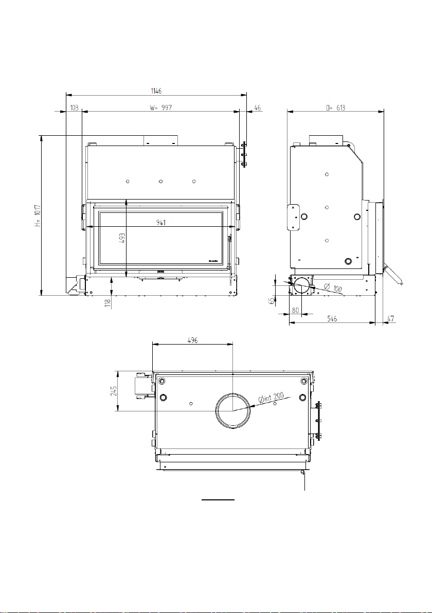
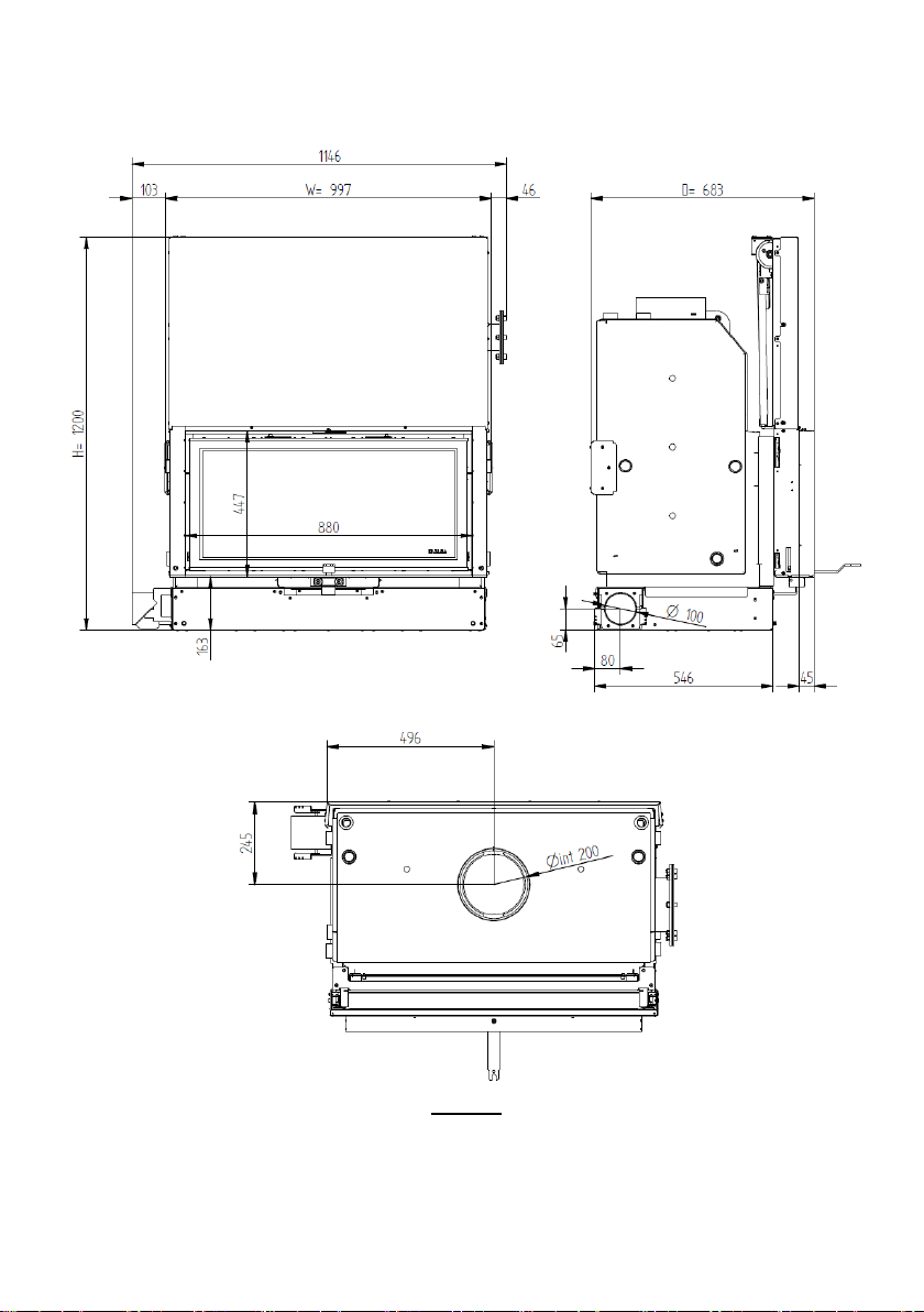
Width
989
997
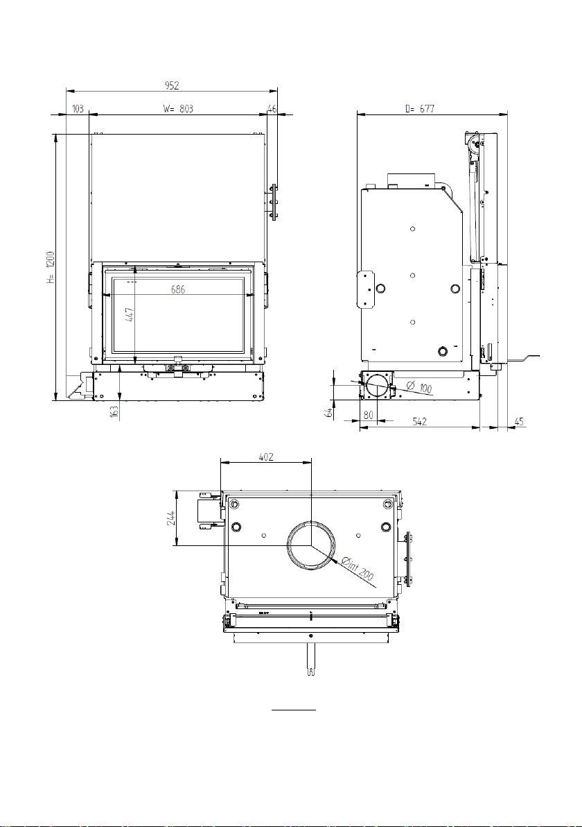
795
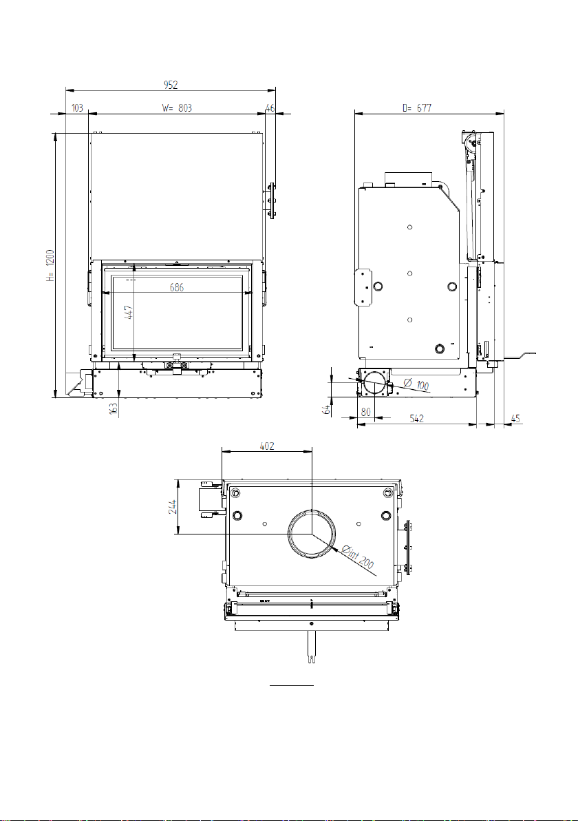
795
803
795
mm
Height
994
1200
994
994
1200
994
mm
Depth
612
683
605
605
677
600
mm
Diameter of the smoke
discharge pipe
200
200
200
200
200
200
mm
Maximum heating volume
641
641
493
493
493
493
m³
Rated thermal input
28,2
28.2
21,7
21,7
21.7
21,7
kW
Air thermal power
9,5
9,5
6,3
6,3
6,3
6,3
kW
Thermal power water
18,7
18,7
15,4
15,4
15,4
15,4
kW
Fuel consumption
8,3
8,3
6,2
6,2
6,2
6,2
kg/h
Recommended firewood length
500
500
500
500
500
500
mm
Maximum firewood length
800
800
600
600
600
600
mm
Thermal efficiency at rated
thermal input
80
80
80
80
80
80
%
Flue gas temperature
323
323
294
294
294
294
°C
CO emissions (13% O2)
0,068
0,068
0,066
0,066
0,066
0,066
%
CO2emissions
11,4
11,4
11,9
11,9
11,9
11,9
%
Particles (13% ofO2)
31
31
11
11
11
11
mg/Nm³
OGC (13% ofO2)
26
26
41
41
41
41
mg/Nm³
NOX(13% of O2)
103
103
88
88
88
88
mg/Nm³
Flue gas mass flow
21,6
21,6
15,3
15,3
15,3
15,3
g/s
Depression in the chimney
12
12
12
12
12
12
Pa
4
3. General measures
Acqua Eco
Figure 1
5
Acqua Eco PV
Figure 2

6
Ecofogo Eco
Figure 3
7
Mytho Eco
Figure 4
8
Mytho Eco PV
Figure 5

9
Zaima Eco
Figure 6
10
4. Know the equipment
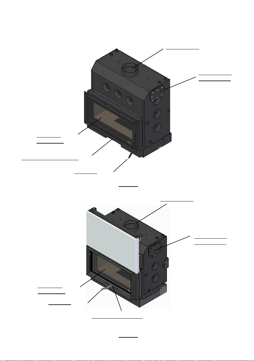
Acqua Eco
Figure 7
Acqua Eco PV
Figure 8
Smoke output
Optional anti-
packaging kit
Vermiculit
plaquesand
Input regulator from ar
Door lock
Vermiculit
plaquesand
Input regulator from
ar
Door lock
Optional anti-
packaging kit
Smoke output

11
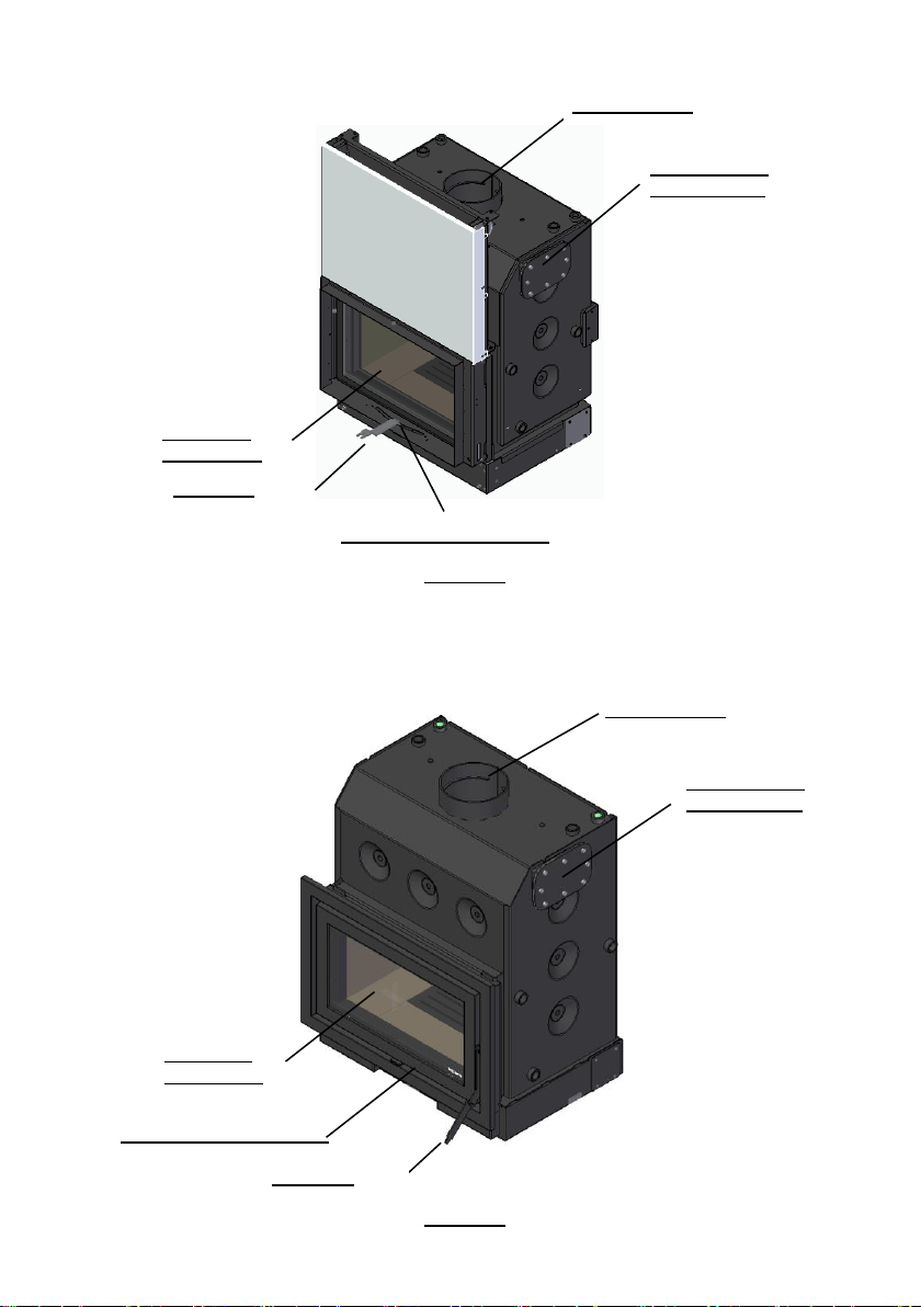
Ecofogo Eco
Figure 9
Mytho Eco
Figure 10
Smoke output
Optional anti-
packaging kit
Input regulator from ar
Door lock
Vermiculit
plaquesand
Smoke output
Optional anti-
packaging kit
Vermiculit
plaquesand
Input regulator from ar
Door lock
12
Mytho Eco PV
Figure 11
Zaima Eco
Figure 12
Smoke output
Optional anti-
packaging kit
Smoke output
Optional anti-
packaging kit
Vermiculit
plaquesand
Input regulator from ar
Door lock
Vermiculit
plaquesand
Door lock
Input regulator from ar

13
5. Materials of the recuperators
The interior of the combustion chamber of these recuperators is made of high-quality
carbon steel sheet with a thickness of 5 mm;
In the ECOFOGO ECO, MYTHO ECO and ACQUA ECO models, the door is made of 2.5
mm plate, in the ACQUA ECO PV and MYTHO ECO PV models with 3.0 mm. In the ZAIMA
ECO model, the door and rim are made of cast iron. The ash drawer on all models is
1.5mm. In the ACQUA ECO, ACQUA ECO PV, MYTHO ECO and MYTHO ECO PV models, the
door has a screen-printed glass-ceramic glass on the outside;
The models ECOFOGO ECO, MYTHO ECO, MYTHO ECO PV, ZAIMA ECO, ACQUA ECO
and ACQUA ECO PV have a heat-resistant glass-ceramic glass. This type of glass can
withstand temperatures of up to 750°C in continuous use;
The hydraulic connections are made of steel, 4 1" female bonds and 2 3/4" female
bonds;
The paint contains paint resistant to temperature peaks of up to 900°C, and to service
temperatures of about 600°C;
In the ECOFOGO ECO, MYTHO ECO, MYTHO ECO PV, ZAIMA ECO, ACQUA ECO and
ACQUA ECO PV models, the combustion chamber is coated with a heat-resistant material
(vermiculite). The lateral insulation, the back, the bottom of the deflectors are of
vermiculite, a material classified as a mineral of the hydro silicate group, resistant to
temperatures of about 1,100 °C. Due to its insulating characteristics, vermiculite allows
a better use of heat, an increase in temperature inside the chamber and cleaner
combustion (with a lower proportion of CO), as well as greater protection of the steel plate
from which the combustion chamber is made, thus prolonging the life of the recuperator;
The models ECOFOGO ECO, MYTHO ECO, MYTHO ECO PV, ZAIMA ECO, ACQUA ECO
and ACQUA ECO PV have a side cover, which allows the installation of an anti-packaging
kit (sold separately).
Installation instructions for this kit can be found in section 6.5 Installation of the anti-
packaging kit.

14
The anti-packaging kit is a mechanical safety system that prevents the equipment
from being damaged by an excess of temperature due to, for example: damaged pump,
electric current cut, etc.
The kit consists of a copper coil welded to a cap that is bolted to the body by replacing
the blind cap with 8 M8 screws. To ensure the tightness between the cap and the body, a
silicone joint is applied, which will ensure that no leaks occur. A thermal discharge valve
(not included in the kit) must be connected to the coil inlet and the outlet must be
connected to the sewer. When the water inside the body reaches a temperature higher
than 97 ± 3 °C, the valve opens the water supply network. As water circulates through
the coil, it absorbs excess heat from the water in the body, thereby reducing body
temperature. The water that has passed through the coil absorbing excess heat is directed
into the sewer.
15
6. Installation
Please note: all local regulations and standards must be complied with when installing this
equipment.
Check, immediately upon receipt, that the product is complete and in good condition.
If there is any defect or malfunction, do not install the equipment and request
the presence of the equipment supplier or a technician of the brand on site.
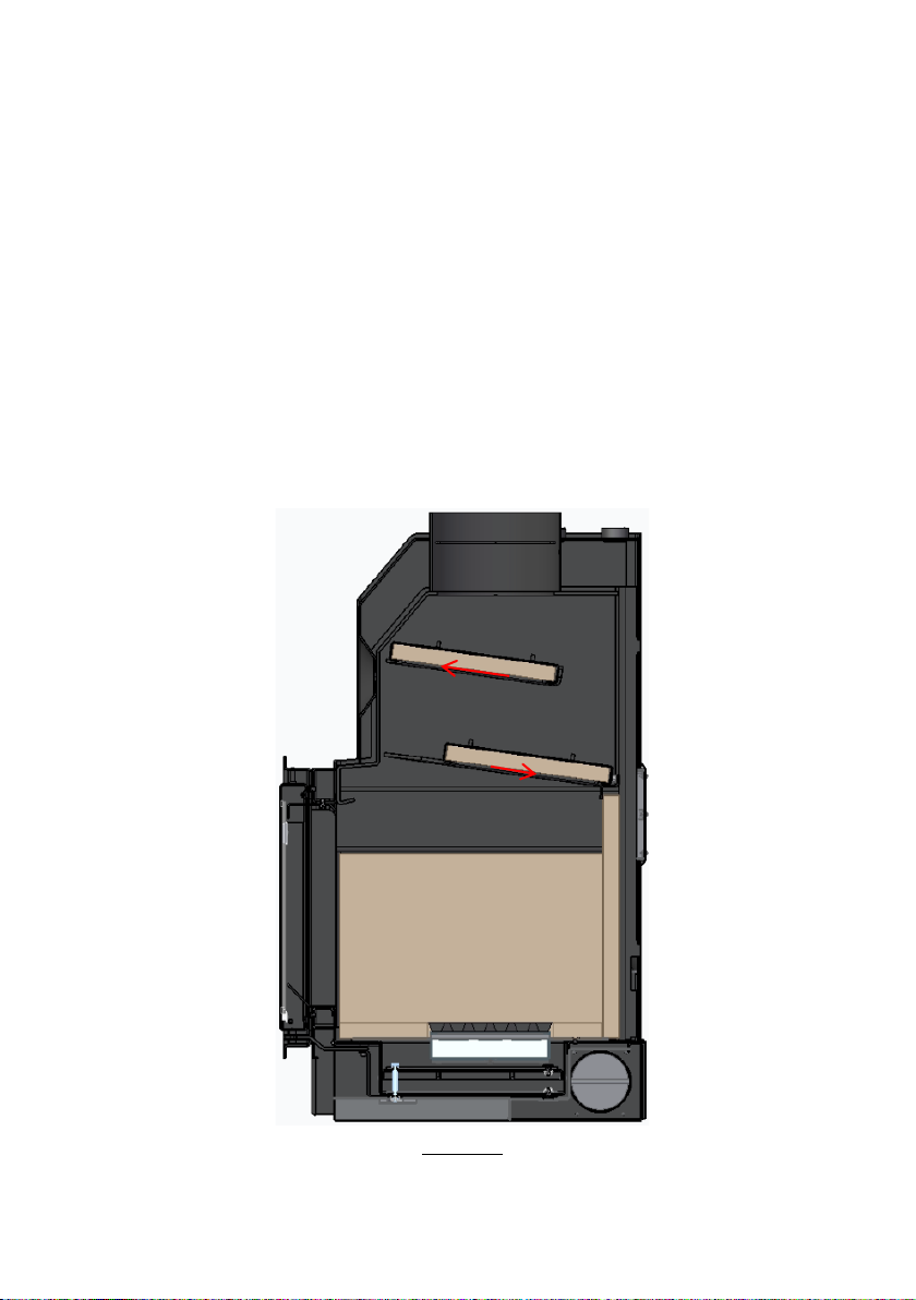
Check that the deflector plates are correctly placed and supported on the supports that
are welded to the sides of the body, see the following image to understand their correct
position;
Figure 13
If they are not properly applied or if it is necessary to put them back on, you should
proceed as follows:
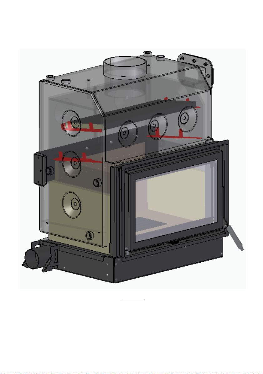
16
- Insert the first deflector plate diagonally and place it on top of the upper brackets, place
it horizontally and lower it slowly so that the plate is centered between the side brackets
(red in the image) and leaning against the front of the body of the equipment
Figure 14
- Insert the second deflector plate in the same way as the first, up to the supports in red.
Place it in a horizontal position and slowly lower the plate so that it is centered between
the side supports (red in the image) and against the back of the combustion chamber.
This manual suits for next models
5
Table of contents
Other SOLZAIMA Stove manuals


Popular Stove manuals by other brands

LA NORDICA
LA NORDICA ROSSELLA PLUS Instructions for installation, use and maintenance

Morso
Morso S11 Series Installation

Lumme
Lumme LU-HP3640C user manual

L'Artistico
L'Artistico Pellicano M14 Installation, use and maintenance manual

Harman Stove Company
Harman Stove Company XXV Installation & operating manual

FAIR
FAIR BIO80 manual

Quadra-Fire
Quadra-Fire GARN-DMBK-IPI-B installation manual

MCZ
MCZ GHEA AIR 6 XUP! S1 installation guide

United States Stove Company
United States Stove Company 1269E owner's manual

NARVI
NARVI ELECTRON 450 Installation and instruction manual

Earth Stove
Earth Stove ES2100 Installation and operation instructions

Bullerjan
Bullerjan 00 manual


