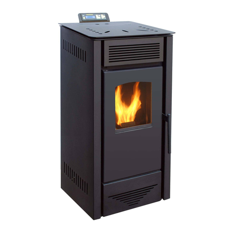
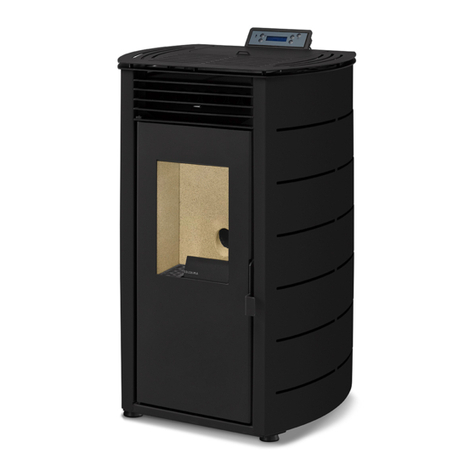
SOLZAIMA AMBER User manual

Instruction Manual
English
Firewood Round Stove
AMBER
Mod. 940 – B

2
Thank you for purchasing a SOLZAIMA appliance.
Please read this manual carefully and retain it for future reference.
* All products here detailed meet the requirements of the EU Construction Products Regulation (No.
30 /2011) and bear the E conformity marking;
* SOLZAIMA disclaims any responsibility for damage to the unit when installed by non-qualified
personnel;
* SOLZAIMA disclaims any responsibility for damage to units not installed and operated in compliance
with the instructions included in this manual;
* All local regulations, including but not limited to national and European standards, must be observed
when installing, operating and servicing the unit;
* SOLZAIMA free standing fire units are tested and found to be in compliance with the EN 13240:2002
+ EN 13240:2002/A2:200 + EN 13240:2002/AC:2006 + EN 13240:2002/A2:200 /AC:2006
standards;
* Technical support is normally provided by SOLZAIMA, except in special cases to be determined by
the installer or support technician;
* For assistance, please contact the unit’s supplier or installer. Please provide the unit serial number,
which can be found on the identification plate located on the back of the unit, as well as on the sticker
posted on the back cover of this manual.
You may contact us via email, using the following address: apoio[email protected].

3
Contents
Page
1. Solzaima .......................................................................................................................... 4
2. Technical specifications ...................................................................................................... 4
3. Unit components ............................................................................................................... 6
3.1. Components .................................................................................................................. 6
3.2. Opcionals ...................................................................................................................... 7
4. Assembly and disassembly of casings ................................................................................. 12
. Installation ..................................................................................................................... 14
.1. Combustion air and gas circulation ................................................................................. 14
.2. Installation space requirements ...................................................................................... 16
6. Instructions for use .......................................................................................................... 17
6.1. Fuel ............................................................................................................................ 17
6.2. Power ......................................................................................................................... 18
6.3. Combustion Principles ................................................................................................... 18
6.4. Air control ................................................................................................................... 19
6. . Energetic efficiency and performance ratings ................................................................... 20
7. Using the unit for the first time.......................................................................................... 21
8. Normal usage .................................................................................................................. 21
9. Safety ............................................................................................................................ 22
10. Cleaning and Maintenance ................................................................................................ 23
10.1. Cleaning .................................................................................................................... 23
10.2. Removing the fume baffle ............................................................................................ 23
11. Troubleshooting ............................................................................................................... 24
12. End-of-life units ............................................................................................................... 2
13. Sustainability .................................................................................................................. 2
14. Glossary ......................................................................................................................... 26
1 . Warranty ........................................................................................................................ 27
16. Statement of performance ................................................................................................ 33

4
1. Solzaima
Solzaima's vision has always been to provide clean, renewable and more cost-effective energy. This is
why we have been manufacturing biomass units and heaters for the past 40 years.
As a result of the persistence and unconditional support from a network of partners, Solzaima is
currently the leading manufacturer of biomass heating units, especially with its range of central
heating stoves with backboilers.
We provide approximately 20000 homes a year with biomass heating solutions. This market has been
growing at annual rate of 20%, indicating that consumers are becoming increasingly aware of
ecological and more cost-effective heating solutions.
Solzaima is the only Portuguese manufacturing company to have obtained ISO 9001 International
Quality Certification and ISO 14001 International Environmental Certification– because we believe in
high standards and aim to lead by example.
2. Technical specifications
Solzaima's free standing fires are designed as interior heating appliances. These units are easy to
install and do not require any kind of finishing, thus promoting their seamless integration with the
room setting.
* Technical specifications across the free-standing fire range:
* CE approved
* Fuel: Dry firewood
* Type of Equipment: Intermittent
* The combustion chamber and external casing of all our free-standing fires are made of first-rate
carbon steel plate, with thicknesses varying between 4 mm and 1, mm, respectively.
* Heat-resistant ceramic glass. Withstands continuous operation temperatures of up to 7 0°C.
* Coated with heat-resistant paint for temperature peaks up to 900°C and operating temperatures of
around 600°C.

5
Figure 1 - Equipment identification – Amber
Front Side Back
Top
Figure 2 - General dimensions of the Amber stove

6
Features Amber
Flue Ø (mm) Ø 1 0 int.
Rated power (kW) 7,3
Performance (%) 81
CO emission (13 %O
2
) (%) 0,0727
CO
2
emission (vol.-%) 8,67
Average temperature of combustion products (°C) 233
Combustion flow (g/s) 7
Weight (kg) 11
Maximum heated volume (m
3
) 166
Firewood length (mm) 300
Firewood consumption (kg/h) 1,6
Height (mm) 11 3
Widdth (mm) 38
Depth (mm) 06
Particles (mg/Nm3) 13
OCG (mg C/m3) 88
NOX (mg/m3) 81
Table 1 - Technical characteristics of Amber stove
3. Unit components
3.1. omponents
Figure 3 - omponents of the Amber stove
Subtitles:
A – Top cover
B – Door
C – Side cover
D – Wooden Base
E – Door handle
F – Glass cleaning palle
G – Door isola ion cord
H – Firewood s orage
I – Ash drawer
J – Primary air
L – Vermiculi e
K – Ash grid
M – Air inle
N – Secondary air
O – Fume baffle
P – Double baffle
Q – Fume ou le
L
B
D
A
E
F
P
Q
O
G
H
I
J
K M
N

7
3.2. Optional
3.2.1. Vertical/horizontal fume outlet
The Amber stove has the option of using the smoke outlet horizontally or vertically, the latter being
the way in which the salamander is prepared for the customer.
To convert the smoke outlet to horizontal mode, the vermiculite pieces must be removed from the
combustion chamber, the double baffle must be removed by loosening the two screws that fix it, and
the screws that fix the neck must be loosened. Then do the reverse process to reposition the parts
you have removed.
With the bottleneck in the horizontal position, it may originate some smoke exit through the door, at
the moment of lighting the equipment, for this reason, it is recommended that the bottleneck is in the
vertical position, to obtain a good draught of smoke and reduce the smoke exit at the moment of
lighting.
3.2.2. onnecting the external air inlet
If you wish to use the external air inlet, you should purchase this optional kit separately.
The purpose of this optional accessory is to establish a connection point between the equipment and
the outside ambient air, thus installing a more suitable piping for this purpose. This optional accessory
is intended to provide the connection of a tube that allows the equipment to be supplied with air from
outside.
You can supply the equipment with outside air in the following ways:
1- From the back of the equipment in the lower area:
If i is a he rear of he equipmen a he bo om of he side covers, as shown in Figure 4, he microdo s
of he side covers mus be broken (M).
Figure 4 - Rear view of the equipment; (M) section to remove for external air inlet
Then remove the cover that blocks the external air inlet by loosening the 4 nuts as shown in Figure .
(M)

8
Figure 5 - Rear view of the equipment; (M) section to remove for external air inlet
After removing the cover, place the optional air inlet kit as shown in Figure 6, tightening the kit with
the 4 nuts that come in the package.
Figure 6 - Rear view of the equipment, placement of the outside air inlet kit
The cover that you removed to place the external air inlet kit must be placed in the lower part of the
equipment, as shown in Figure 7, to do this you must loosen the 3 screws that fix the base to the
equipment to have access to the place where you place the cover.
Then you must fix the cover with the 4 nuts that you removed from the rear of the equipment, thus
covering the external air intake.
Figure 7 - Bottom view of the equipment, blocking the external air intake under the equipment
Unscrew he 4
nu s and remove
he cover.
Placemen of
he ou side air
inle ki .
Loosen he 3 screws ha fix he base o he equipmen .
Fixing he cover, blocking he ou side air in ake.

9
2- From the base of the equipment
If the installation of the air inlet kit is from the base of the equipment, you can choose from 2
installation zones, from the back of the base or from below the base as shown in Figure 8.
You must break the micro assemblies of the zone (M), using the option you chose to apply the kit.
Figure 8 - External air inlet, (M) section to be cleared for external air inlet
The external air inlet kit must be placed in the lower area of the equipment, as shown in Figure 9. To
do this, loosen the 3 screws that fix the base to the equipment and apply the external air inlet kit with
the 4 nuts that come in the package.
Figure 9 - Bottom view of the equipment, application of the external air inlet kit
3.2.3. Optional Modules
3.2.3.1. Firewood Base Door
If you want to put the door in the base of the equipment, you must purchase this accessory separately
and must follow the following steps.
Ou door air inle ki , from
he rear of he base.
Ou door air inle ki , from
he bo om of he base.
(M)
(M)
Loosen he 3 screws ha fix he base o he equipmen
A achmen of he ex ernal air inle ki

10
1- Using a key, carefully fold the tab on the right side of the base, so that it is perpendicular to the
side, as shown in Figure 10.
Figure 10 - Preparation of the base of the equipment, to place the door
2- Place the magnet on the bent tab and secure it with the nut. These accessories come with the door
Figure 11.
Figure 11 - Preparation of the base of the equipment, to place the door
3- Place the door on the base by first inserting the door axes in the upper hole of the base and then in
the lower hole of the base, as shown in Figure 12.
Figure 12 - Placing the door on the base of the equipment
Place he upper axis of he door, on he upper
axis of he base, wi h he door semi
-
open.
Til ing o place he door on
he
base.
Place he lower axis of he door on he
lower axis of he base.

11
NOTE:
So that the door, once fitted to the base, aligns with the circumference of the equipment, you can do
so by adjusting the door handle, giving more or less inclination.
You can also adjust the alignment of the door, by the tab of the base, also giving more or less
inclination.
3.2.3.2. Top cover in stone
Vertical smoke outlet - If you want to apply a stone worktop, simply remove the worktop by pulling
it upwards, loosen slightly the 2 screws indicated in Figure 13 so that the screw head is higher than
the side covers, then apply the stone worktop, fitting the two cavities that have the stone worktop in
the 2 screws.
Figure 13 - Placing the top cover on the equipment with vertical smoke outlet
Horizontal smoke outlet - Place and fix the board that comes with the stone worktop with two
screws and loosen the two screws of the machine 1 cm where the stone worktop will fit, as shown in
the following pictures.
Figure 14 - Placing the top cover on the equipment with horizontal smoke outlet
Loosen he 2 screws

12
4. Assembly and disassembly of casings
If you need to remove the casings from the equipment, you should follow this procedure:
1- Remove the top, just lift it up, as shown in Figure 1 .
Figure 15 - Disassemble the worktop in the equipment
2- Loosen the screws on the upper part of the casings, as shown in Figure 16, so that the
casings are free.
Figure 16 - Disassembly of the side casings in the equipment

13
3- Disassembly direction, to remove the casings, follow the direction of the arrows, as shown in
Figure 17.
Figure 17 - Disassembly of the side casings in the equipment
4- When you are about to mount the side casings pay attention to the following, the lower area
of the covers has 2 holes, these holes, must match the screws that come in the machine,
you can see in Figure 18.
Figure 18 - entering of the side casing with the equipment
Disman ling direc ion of
he lef side casing.
Direc ion of disassembly
of he righ -side casing.
Regula or side.

14
- Then, tighten the casings in the upper area of the equipment by tightening the screws as
shown in Figure 19.
Figure 19 - Assembly of the side casings in the equipment
5. Installation
Warning: when installing this unit, be sure to follow all model-specific information, warnings, safety
notices and local codes.
5.1. ombustion air and gas circulation
* This heating appliance must be installed in a well-ventilated area. Any required air inlet vents must
be installed where not prone to becoming blocked;
* The air for combustion goes into the unit through the combustion air inlet located at the bottom of
the unit. This air flow should be kept clear of obstacles at all times;
* Additional air inlets may be needed if the unit is used concurrently with other appliances that require
an air supply. The installer should assess this need, according to the existing appliances overall air
flow requirements;
* The Amber units cannot be installed in areas where air extraction appliances, such as kitchen
extractor fans, may operate simultaneously, as this may prevent the correct operation of the unit;
* Under rated operating conditions, the circulation of combustion gases should create a draught of 12
Pa about one metre above the chimney throat. For proper installation, at least 2 metres of metal flue
tubing, with the same diameter as the unit's smoke outlet, should be fitted vertically above the unit.
Additional lengths to this tubing may use piping sections with a max angle of 4 °. Figure 20 and 20
illustrate the correct and incorrect angles for pipe elbows, should they need to be installed.

15
Figure 20 - orrect elbow angle
Figure 21 - Incorrect elbow angle
* Single-walled tubes installed on the exterior of a building results in the condensation of water
vapour in the combustion gases. To prevent this, we recommend that you use a double-walled,
insulated tube.
* All tube bindings should be properly sealed to prevent the admission of air through any existing
fissures;
Figure 22 - orrect sealing Figure 23 - Incorrect sealing
* Ensure that the tube bindings do not strangle the tube (narrowing the flow), the inner tube walls are
smooth and free of obstacles, and that the caps do not disturb the air circulation;
Figure 24 - Incorrect binding Figure 25 - orrect binding
* The chimney dome should allow proper air circulation and be placed at least 1 m above the roof
peak or 3 m away from other obstacles. If you need to increase the air circulation, you should extend
the height of the flue;
Minimum dis ance
equivalen o he
ube diame er

16
Figure 26 - Incorrect chimney height Figure 27 - orrect chimney height
* Never use the same chimney flue for more than one unit or open fireplace. For shared chimneys,
each flue should individually reach the external outlets at the same level, to ensure that the air
circulation adequately expels the exhaust fumes;
* If the chimney is made of brick, the flue should extend up to the very top, preferably in isolation.
Otherwise, the fume temperature will drop, impairing air circulation. A suitable cap should be installed
at the top of your chimney in accordance with its air circulation condition. Depending on atmospheric
conditions, other types of chimney caps may be installed, such as the rooster cap.
5.2. Installation space requirements
* The unit should stand on a masonry hearth made of refractory bricks or other type of non-
combustible material;
* Keep any combustible materials away from this appliance. For safety reasons, you should maintain a
minimum clearance distance around the unit of 20 cm from the back, 30 cm from the sides and 120
cm from the front (Figure 28);
Figure 28 - Minimum safety distances
* The floor on which the unit will stand must be capable of supporting a permanent load of 1 kg (2,2
lbs)/cm². If the floor's bearing capacity is insufficient, a solid plate may be used to distribute the load
over an area larger than the base of the unit;
A minimum of 1
m above he
highes poin

17
* Before proceeding with the installation, please check whether the intended location allows an easy
access to the unit, to facilitate any cleaning procedures as well as the inspection of the fume outlet
connection;
* Please make sure the air intake vents from the building are not obstructed;
* Ensure that the structure built into the wall is of an appropriate size to house the unit;
* Any materials/objects placed near the unit should be capable of withstanding the heat radiated
through the glass and walls of the appliance, so no combustible materials are allowed;
* A refractory material - refractory cement or other - should be applied around the chimney gasket.
* The use of wood in the finishing may increase the risk of fire. We therefore recommend that any
wood used be adequately insulated, or that no wood be used at all.
6. Instructions for use
6.1. Fuel
* Only firewood should be used in this type of appliance. The unit cannot be used as an incinerator,
nor should other materials such as coal, painted wood, varnishes, thinners, liquid fuels, glues or
plastics be used as fuel. Also avoid burning common combustible materials, such as cardboard and
straw;
* Do not use exotic firewood as fuel;
* The firewood used with this appliance should have low water content (less than 20%). We
recommend that it should be placed under covered storage for around 2 years after felling, in order to
ensure efficient combustion and avoid creosote build-up in the smoke duct, combustion chamber and
on the glass. See the list in Table 2, for additional information on the types of wood that can be used
in these units;

18
Common name Scienti ic
name
Distribution
(total: 18 districts) Notes
Features
Smoke Heat Lighting Combustion
Speed
Hardness
Pine Pinus
Bragança, Castelo
Branco, Coimbra,
Guarda, Leiria,
Viana do Castelo,
Vila Real and Viseu
Predominant
s ecies Little High Easy Fast Soft
Cork Oak Quercus suber
Évora, Faro,
Portalegre,
Santarém and
Setúbal
Predominant
s ecies Little Very High Easy Regular Hard
Eucaly tus Eucaly tus Aveiro, Porto and
Lisbon
Predominant
s ecies A lot Regular Difficult Slow Hard
Holm Oak Quercus ilex Beja and Évora Predominant
s ecies Little Very High Difficult Slow Hard
Olive tree Olea
Entire country
exce t mountainous
regions
Less redominant
than above Little Very High Difficult Slow Hard
Oak Quercus Entire country, with
range of subspecies
Less redominant
than above Little High Difficult Slow Hard
Ash Fraxinus Riverbank areas
(Lower Vouga)
Small numbers
distributed around
the country
Regular High Difficult Slow Hard
Birch Betula High ground (Serra
da Estrela)
Smaller numbers
distributed around
the country
Little Very High Easy Fast Soft
Beech Fagus
old, humid regions
(North of Portugal –
- Serra do Gerês)
Smaller numbers
distributed around
the country
Little High Difficult Slow Hard
Ma le Acer Minho, Beira Litoral
and Serra de Sintra
Smaller numbers
distributed around
the country
Little Regular Regular Slow Soft
Po lar Po ulus Entire country, but
mainly in the entre
Smaller numbers
distributed around
the country
Little High Easy Fast Soft
Chestnut Castanea
Northern and centre
part of Portugal, and
mountain regions
Smaller numbers
distributed around
the country
Regular High Difficult Slow Hard
Table 2 - Types of firewood that may be used in SOLZAIMA heat exchanger appliances, their geographical distribution and respective
calorific value/reactions
6.2. Power
* The power of your unit translates its heating capacity, i.e. the heat transfers your unit gets from the
energy of the firewood used (usually measured in kW), which is directly dependent on the amount of
firewood placed in the units.
* The rated power is measured for standard load of firewood when tested in laboratory conditions over
a specific period of time.
6.3. ombustion Principles
The stove is designed to be a slow-burning device. With a maximum wood charge and a gentle flame,
it will heat up with maximum efficiency for several hours. The salamander may burn very slowly with
a low flame for a few hours. However, we do not recommend this procedure because incomplete
combustion creates smoke which, when condensed, deposits tar in the stove, chimney and glass
panel. An accumulation of tar becomes unpleasant to the eye and also requires more frequent

19
chimney cleaning to prevent possible fires in the chimney. If you are using wet or green firewood, the
combustion control should always be more open to ensure proper combustion.
Radiant heating
It is emitted by the embers, the steel plate and the vermiculite plates on the back of the stove. The
radiant heating is also transmitted through the glass to the compartment and heats the area in front
of the stove.
onvection heating
Cold air passes through the crankcase from the bottom, running across the back and top of the
equipment, expelling hot air from the front of the equipment.
This convective hot air reaches the far corners of the room.
Figure 29 - onvection circuit represented in the stove
6.4. Air control
ombustion air control
The combustion air regulator is shown in Figure 30. It controls the amount of air entering the
salamander, thus controlling the burning of the fuel. On the side of the salamander there is 1
regulator that regulates the primary and secondary air at the same time.
Primary air
Secondary air
Glass
cleaning
Outside air inlet
Outside air inlet
Outside air inlet
Fume outlet
Fume outlet
Color legend:
Warm air
Prehea ed air
Cold air

20
The primary air must be open during starting, until the wood is properly started, i.e., all the regulator
is in the (+) position. On the side cover, there is a mark indicating the point from which the primary
air is completely closed and part of the secondary air is open.
After igniting, and for good combustion, the regulator should be between the markings, as you can
see in Figure 30.
Figure 30 - Air regulator in equilibrium point position
The secondary air also has the function of cleaning the glass, creating a sweeping effect through the
passage of preheated air over the entire interior surface of the glass, helping to keep the glass cleaner
for longer.
6.5. Energetic efficiency and performance ratings
* The implementation of solutions promoting greater energy efficiency results in a substantial
reduction in energy needs, which in turn helps reduce our current dependence on fossil fuels and other
non-renewable sources of energy. Energy efficiency therefore encourages significant savings, both
economically and environmentally speaking.
* Solzaima's commitment to developing energy efficient heating units results in products that can
claim to have an efficiency rate equal or above 70%. A 70% efficiency rate means that 70% of the
energy contained in the firewood is used to warm your home or, in other words, you are able to
produce the same amount of energy with much less firewood. A Solzaima unit of kW with an
efficiency rate of 7 % is expected to consume approximately 1,6 kg (3, lbs) of firewood per hour to
heat a 3 m
2
(377 sq ft) room.
* Generally, the efficiency rate of a traditional fireplace is only about 10%, which means it will need to
consume approximately 12 kg (26, lbs) of firewood to produce the same kW required to warm the
same 3 m
2
(377 sq ft) room.
Primary air
closed.
Secondary air
closed.
Primary air closed.
Secondary air partially open. Primary air
open.
Secondary air
open.
-
+
Table of contents
Other SOLZAIMA Stove manuals
Popular Stove manuals by other brands

Palazzetti
Palazzetti ECOFIRE series USE AND FUNCTION

Regency
Regency U39-NG11 Owners & installation manual

Piazzetta
Piazzetta Vera - Vittoria Installation, use and maintenance instructions

Harman Stove Company
Harman Stove Company SF-150 SF-250 Installation and operator's manual

Breckwell
Breckwell Charm P22FS owner's manual

HASE
HASE Elvas operating instructions

LA NORDICA
LA NORDICA TermoRossella Plus DSA Instructions for installation, use and maintenance

Premium
Premium GPEES30C Installation and maintenance manual

Primus
Primus Techno Trail Instructions for use

IronStrike
IronStrike EPIC33 Installation and operation guide

wiking
wiking Nordic 9G Installing

Lopi
Lopi Deerfield manual