SOLZAIMA K2 K100 User manual

Pellet Stove
Instruction Manual
Models
K100
K200
K300
K400
K500
K600
FUJI
FUJI
PINE 8kW
PINE 10kW
AMAZON 9kW
ASPEN 12kW
K2
K2
ASPEN 8kW
ASPEN 10kW
FUJI 12kW
HIMALAIA
HIMALAIA
OLIVE 8kW
OLIVE 10kW
HIMALAIA 12kW
KILI
LEAF 8kW
LEAF 10kW
K2 12kW
PICO
ALPES 8kW
ALPES 10kW
PINE 12kW
Read these instructions carefully before installing, using and servicing the unit. The
instruction manual is an integral part of the product.
Mod.705-K

Thank you for purchasing a SOLZAIMA appliance.
Please read this manual carefully and keep it for future reference.
* All our products fulfil the requirements of the Construction Products Directive (Reg.
UE nº 305/2011) and have been approved with the CE conformity mark;
* The Pellet Burning Free Standing Fires are designed according to EN 14785:2008
Standards;
*SOLZAIMA disclaims any responsibility for damages to the unit if installed by non-
qualified personnel;
* SOLZAIMA is not responsible for any damage to units not installed and used in
compliance to the instructions included in this manual;
* All local regulations, including but not limited to national and European standards,
must be observed when installing, operating and servicing the unit;
* Whenever you need assistance, you should contact the supplier or installer of your
equipment. You should provide the serial number of your stove that is located on the
nameplate on the back of the equipment and on the sticker s glued to the plastic cover
of this manual;
*Technical assistance should be carried out by your installer or supplier, except in
special cases after evaluation by the installer or technician, who will contact SOLZAIMA
if necessary.
Contacts for technical support:
www.solzaima.pt
apoio.clien[email protected]
Address: Rua dos Outarelos; nº 111;
3750-362 Belazaima do Chão
Águeda - Portugal

Contents
1. Solzaima..................................................................................................1
2. Package content........................................................................................2
2.1. Unpacking the unit ...............................................................................2
3. Safety precautions ....................................................................................2
4. Advice on action in the event of a fire in a chimney (including equipment) .......3
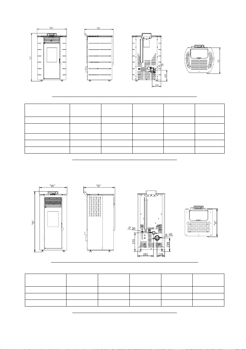
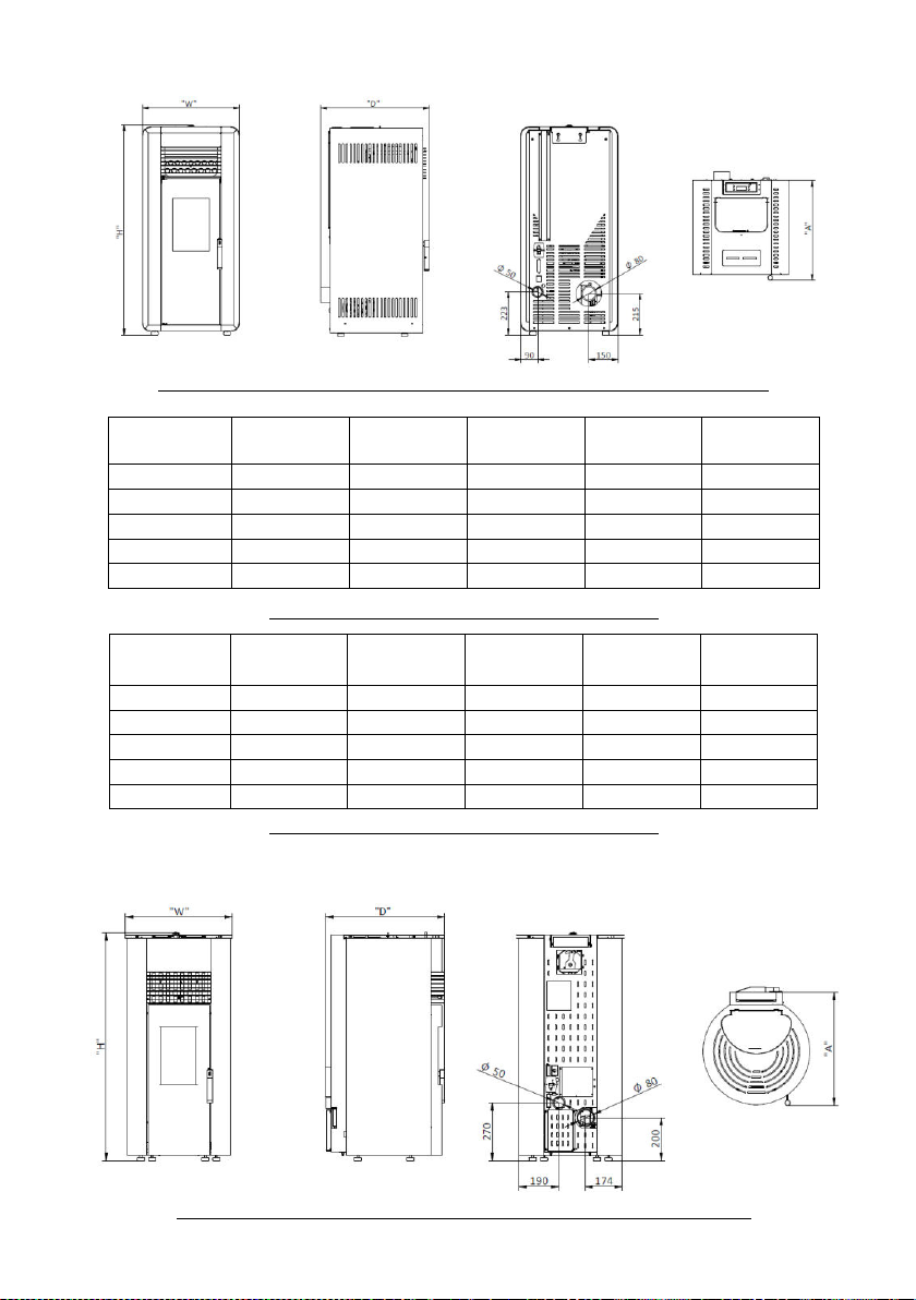
5. Technical specifications ..............................................................................4
6. Installing the free-standing pellet fire .......................................................... 8
6.1. Installation requirements ...................................................................... 8
6.2. Installing ducts and fume extraction systems...........................................9
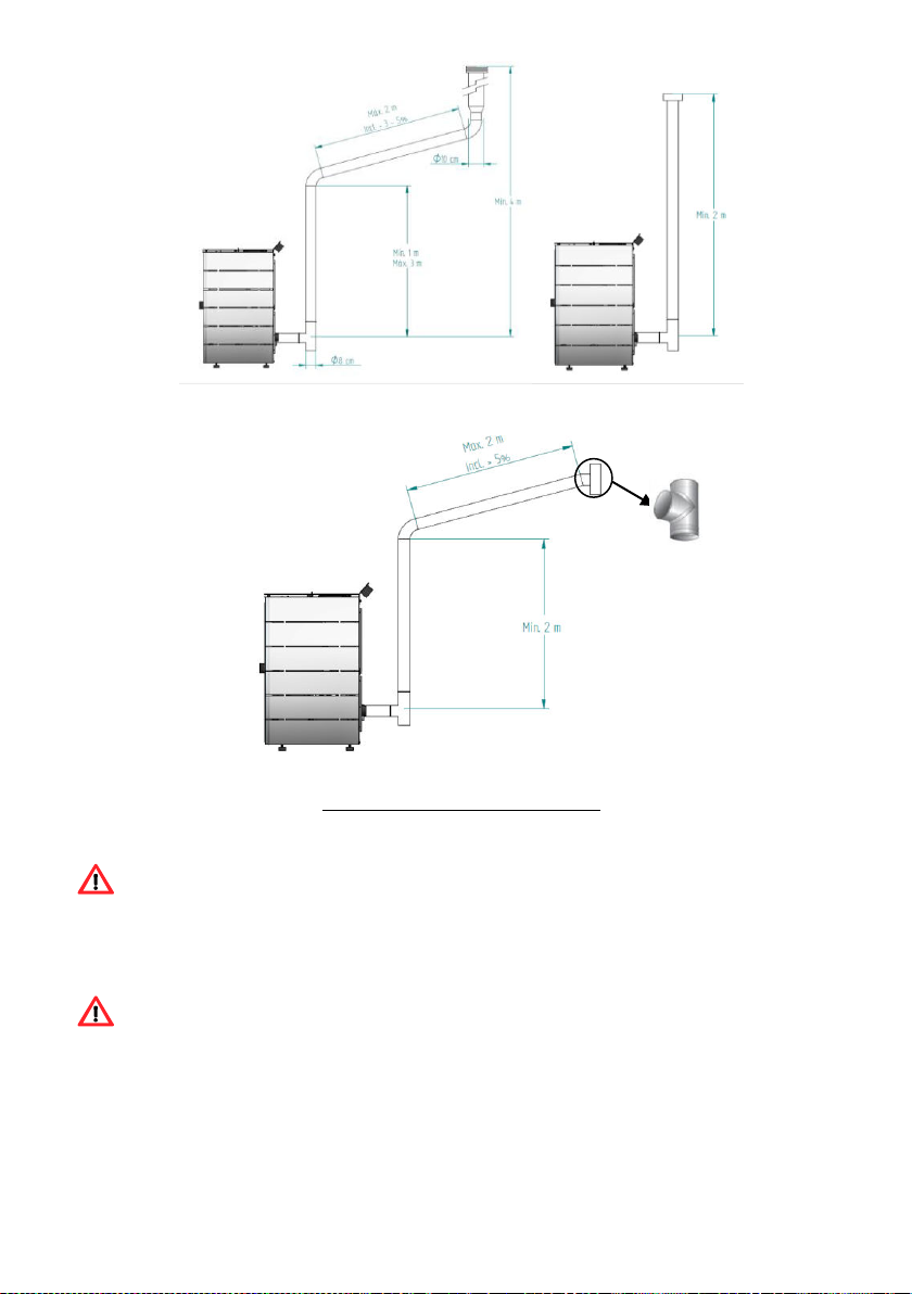
6.3. Installing without a chimney................................................................ 10
6.4. Installing with a chimney .................................................................... 12
7. Fuel....................................................................................................... 13
8. Using the free-standing pellet fire ............................................................. 14
9. Remote control ....................................................................................... 15
9.1. Infrared remote control....................................................................... 15
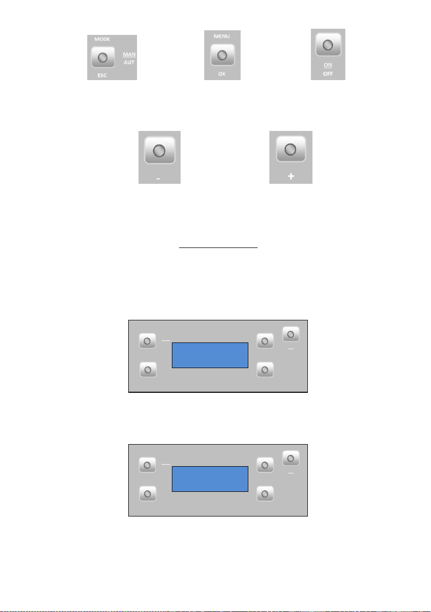
9.2. Control and display panel .................................................................... 15
9.2.1. Selecting the manual or automatic mode.......................................... 16
9.2.2. Date and time............................................................................... 17
9.2.3. Timer........................................................................................... 19
9.2.4. Sleep (this menu is displayed only while the unit is operating) ............ 23
9.2.5. Info ............................................................................................. 23
9.2.6. Settings menu .............................................................................. 26
9.2.7. Technical menu ............................................................................. 29
10. Start-up................................................................................................. 30
11. Instruction for installing the casings .......................................................... 31
11.1. Installing the casings K100 and K200 ................................................... 31
11.2. Installing the casings K300 and K400 ................................................... 38
11.3. Installing the casings Alpes K400 and Alpes K300 .................................. 49
11.4. Installing the casings K500.................................................................. 66
11.5. Installing the casings K600.................................................................. 72
12. Installing the ductable air auxiliary ventilator (PA1090G030 optional only K500)
84
12.1. Electrical connections ......................................................................... 88
12.2. Adjustable ductable air inlet ................................................................ 90

12.3. Recommendations for the installation of the ductable air (K500) .............. 91
13. Installing the ductable air auxiliary ventilator (PA1090G038 optional only K600)
92
13.1. Electrical connections ......................................................................... 97
14. Refilling the pellet reservoir...................................................................... 98
15. Maintenance........................................................................................... 98
15.1. Daily maintenance.............................................................................. 98
15.1.1. Cleaning the glass ......................................................................... 99
15.1.2. Cleaning the unit........................................................................... 99
15.2. Weekly maintenance........................................................................... 99
15.3. Additional cleaning ........................................................................... 100
16. Alarm / Failure / Recommendation List..................................................... 103
17. Installing and operating with the remote control - “programmable thermostat”
(optional)....................................................................................................... 105
17.1. Instructions to assemble the remote control ........................................ 107
18. Maintenance plan and log....................................................................... 109
19. Maintenance guide label......................................................................... 113
20. Electrical diagram of the free-standing fire unit......................................... 114
21. Life cycle of a free-standing fire unit........................................................ 115
22. Warranty.............................................................................................. 115
22.1. Model-specific conditions................................................................... 115
22.2. Warranty general conditions .............................................................. 115
23. Annexes............................................................................................... 124
24. Flow chart............................................................................................ 125
24.1. Flow chart K100, K200, K500 and K600 .............................................. 125
24.2. Flow chart K300 and K400 ................................................................ 128
25. Statement of performance...................................................................... 131

1
1. Solzaima
Solzaima's vision has always been clean, renewable and more economical energy. For
this reason, we have been manufacturing biomass heating equipment and solutions for
more than 45 years.
Fruit of the persistence and the unconditional support of its network of partners,
Solzaima is today leader in the production of biomass heating, whose best examples
are the recuperators of central heating to water and its range of salamanders to
pellets.
We annually equip more than 20.000 homes with biomass heating solutions. It signals
that consumers are aware of the most environmentally friendly and economical
solutions.
Solzaima has ISO9001: 2015 Quality Certification and ISO14001: 2015 Environmental
Certification.

2
2. Package content
The package of this unit contains:
- Free Standing Pellet Stove K100, K200, K300, K400, K500 and K600 model;
- Access to the online instruction booklet;
- Power cable;
- Infrared remote control;
- Cleaning bar handle;
- Front cover, model K200;
- Covers according to selected model.
2.1. Unpacking the unit
To unpack the equipment, you must first remove the retractable bag that surrounds the
cardboard box. Then remove the box, lifting it up, and remove the bag that surrounds
the stove and the Styrofoam plates. To complete the procedure, unscrew the four
brackets that secure the unit to the wood pallet (Figure 1).
Figure 1 - Unpacking the unit
3. Safety precautions
•Make sure you fully read and understand the instructions contained in this manual
before using the Free-Standing Pellet Stove as a biomass heating unit.
•The Free-Standing Pellet Stove is not intended for use by children or people
physically and/or mentally challenged, or that are inexperienced or unfamiliar with
using the unit, except when under supervision or after receiving proper training.
•Do not touch the Free-Standing Fire when barefoot or if any part of your body is
wet or humid;
•Do not tamper with the safety devices or adjustment features without the
SOLZAIMA SA manufacturer's authorization;
•Do not cover or reduce the size of the vents at the installation area;

3
•The installation of the Free-Standing Pellet Fire has clearance requirements for
proper combustion, so the air tight isolation of the room where the equipment is to be
installed or the existence of air extraction sources in the room may prevent the unit
from working properly;
•The existence of vents is a requirement for proper combustion;
•Please keep the packing materials away from children;
•During normal operation, DO NOT open the door of the unit;
•Some parts may overheat during normal operation, so the direct contact with hot
parts, such as the door handle and glass, should be avoided;
•Check for the existence of any obstructions to the fume duct before turning on the
unit after a long idle period;
•This Free-Standing Pellet Fire unit is intended for residential use in areas with the
adequate protections in place. Safety systems may be triggered, which will be turning
off the unit. If this occurs, contact the technical assistance. Under no circumstances
should you attempt to tamper with the safety systems;
•The Free-Standing Pellet Fire is a biomass heating unit equipped with an electric
fume extractor. The occurrence of a power failure during its use may prevent the fume
to be extracted, consequently causing the room to be filled with smoke. For this
reason, a natural fume extraction system, like a chimney, is recommended;
•NEVER turn off an operating Free-Standing Pellet Fire unit by disconnecting the
electric plug. The fume extractor on the Free-Standing Pellet Fire unit is a powered
feature, so disconnecting the power plug will prevent the extraction of combustion
fumes;
•The unit must be disconnected from the mains power before any maintenance
procedures can be performed. Please allow the unit to cool down completely before any
maintenance operation (if operating before);
•Never touch the interior of the unit without disconnecting it from the power mains.
4. Advice on action in the event of a fire in a chimney
(including equipment)
• Try to put out the fire, without risking your life.
• If you cannot put out the fire within a minute, you should call the fire department.
• Close the doors and windows or the room where the fire has flared.
• Turn off the power and close the gas before leaving your home.

4
• Once outside, you must wait for the firemen and be ready to give them the
following information: location of the fire, possible materials that are burning and what
they can do to prevent fire progression.
5. Technical specifications
Features
K100
K200
K300
K400
K500
K600
Units
Height
“H”
“H”
“H”
“H”
“H”
“H”
mm
Width
“W”
“W”
“W”
“W”
“W”
“W”
mm
Depth
“D”
“D”
“D”
“D”
“D”
“D”
mm
Diameter of the fume discharge pipe
80
80
80
80
80
80
mm
Reservoir capacity
15,0
20,0
15,0
17,0
17,5
30,0
kg
Maximum heating capacity
182
227
182
227
200
269
m³
Maximum overall thermal power
8,0
10,0
8,0
10,0
8,8
11,9
kW
Minimum thermal power
3,0
3,5
3,0
3,5
3,0
3,9
kW
Minimum fuel consumption
0,68
0,77
0,68
0,77
0,68
0,90
kg / h
Maximum fuel consumption
1,8
2,3
1,8
2,3
2,0
2,7
kg / h
Rated electrical current
106
122
106
106
106
106
W
Electric power at start-up (<10 min.)
362
378
362
362
362
362
W
Rated voltage
230
230
230
230
230
230
V
Nominal frequency
50
50
50
50
50
50
Hz
Thermal yield at rated thermal power
91,3
91,4
91,3
91,4
91,0
92,0
%
Thermal yield at reduced thermal power
96,0
96,0
96,0
96,0
96,0
96,0
%
Max. fume temperature
152,6
149,0
152,6
149,0
165,0
125,0
°C
Min. fume temperature
64
59
64
59
64
53
°C
CO emissions at rated thermal power
0,010
0,012
0,010
0,012
0,0095
0,016
%
CO emissions at reduced thermal power
0,027
0,036
0,027
0,036
0,027
0,045
%
Combustion gas mass flow
5
5,0
5
7
5
9,2
g/s
Draught in the chimney
12
12
12
12
12
12
Pa
Table 1 - Technical specifications
Tests were performed using wood pellets with a heating capacity of 4,9 kWh/kg.
The above information was obtained during product homologation tests conducted by independent laboratories
accredited for pellet unit testing.

5
Front Side Back Top
Figure 2-A - Dimensions of the free-standing pellet fire unit K100 (example model K2)
Table 2 - Dimensions of the free-standing pellet fire unit K100
Front Side Back Top
Figure 2-B –Dimensions of the free-standing pellet fire unit K100 (exemple model Fuji)
Table 3 - Dimensions of the free-standing pellet fire unit K200
Model
Dimension
“H” (mm)
Dimension
“W” (mm)
Dimension
“D” (mm)
Dimension
“A” (mm)
Weight
(kg)
K2 K100
908
562
546
490
82
KILI K100
(ceramic/glass/colour)
908
513
544
490
95/92/88
PICO K100
908
559
556
490
90
FUJI K100
908
493
556
490
84
HIMALAIA K100
908
493
544
490
83
Model
Dimension
“H” (mm)
Dimension
“W” (mm)
Dimension
“D” (mm)
Dimension
“A” (mm)
Weight
(kg)
FUJI K200
1076
493
554
494
106
HIMALAIA K200
1076
493
554
494
105
K2 K200
1076
562
554
494
104

6
Front Side Back Top
Figure 2-C - Dimensions of the free-standing pellet fire unit K300 and K400 (example model Leaf)
Table 4 - Dimensions of the free-standing pellet fire unit K400
Model
Dimension
“H” (mm)
Dimension
“W” (mm)
Dimension
“D” (mm)
Dimension
“A” (mm)
Weight
(kg)
PINE K300
966
542
566
519
101
LEAF K300
966
507
566
519
99
ASPEN K300
966
473
566
519
100
OLIVE K300
966
507
566
519
100
ALPES K300
994
492
564
519
103
Table 5 - Dimensions of the free-standing pellet fire unit K300
Front Side Back Top
Figure 2-D - Dimensions of the free-standing pellet fire unit K500 (example model Amazon)
Model
Dimension
“H” (mm)
Dimension
“W” (mm)
Dimension
“D” (mm)
Dimension
“A” (mm)
Weight
(kg)
PINE K400
1088
559
566
519
111
LEAF K400
1088
507
566
519
108
ASPEN K400
1088
473
566
519
110
OLIVE K400
1088
507
566
519
110
ALPES K400
1153
492
551
519
114

7
Model
Dimension
“H” (mm)
Dimension
“W” (mm)
Dimension
“D” (mm)
Dimension
“A” (mm)
Weight
(kg)
Amazon K500
1072
500
561
533
92
Table 6 - Dimensions of the free-standing pellet fire unit K500
Front Side Back Top
Figure 2-E - Dimensions of the free-standing pellet fire unit K600 (example model Aspen)
Model
Dimension
“H” (mm)
Dimension
“W” (mm)
Dimension
“D” (mm)
Dimension
“A” (mm)
Weight
(kg)
Aspen K600
1156
530
596
549
152
Fuji K600
1156
550
596
554
145
Himalaia K600
1156
550
596
554
143
K2 K600
1156
600
596
549
143
Pine K600
1156
626
590
552
152
Table 7 - Dimensions of the free-standing pellet fire unit K600
WARNING!
The free-standing pellet fire may not be used or connected to the mains without proper
Installation of one of the covers available.

8
6. Installing the free-standing pellet fire
Before installing the unit, please follow these steps:
•Check immediately after receipt if the delivered product is complete and in good
state. Any defects should be noted before installing the appliance.
•This unit is equipped with four feet at the base, adjustable in height, allowing for
the easy regulation when installing the unit on a non-levelled surface.
Figure 3 - Adjustable feet
•Remove the instruction manual from the package and hand it over to the client;
•Connect an 80 mm-wide duct between the combustion gas output and the outgoing
fume extraction duct of the building (e.g. chimney). See location diagrams, sections
6.3 to 6.4.
•The tube used for combustion air inlet from the outside, if installed, must be
straight (no bends) and have a maximum length of 60cm horizontally;
•Connect the 230VAC power cable to a grounded socket.
•The hot air outlet side of the unit must be installed facing the area to be heated.
6.1. Installation requirements
The minimum distance between the free-standing pellet fire unit and particularly
flammable surfaces is specified in Figure 4.
The top of the unit must have a separation distance from the ceiling of at least 100 cm,
especially in rooms with ceilings made of flammable materials.
The base used to support the unit cannot be made of combustible materials (e.g.
carpet), so make sure adequate protection is used.

9
a) b)
Figure 4 - Minimum safety distance around the unit: a) top view of the unit installation; b) side view of the unit
installation
WARNING!
Keep combustible and flammable materials at a safe distance.
6.2. Installing ducts and fume extraction systems
•The exhaust pipe must be designed for this specific purpose, in compliance with
local requirements and any applicable regulations.
•Important notice! An inspection-T with an airtight lid must be attached to the
outlet of the unit’s exhaust pipe to allow for the regular inspection of the system or
discharge of heavy dust and condensates.
•Important notice! For the K500 pellet stove, a male/male connection with a
minimum extension of 100 mm must be inserted at the outlet of the stove's exhaust
pipe, and then a T-Inspection must be inserted, with an airtight lid must be attached to
the outlet of the unit’s exhaust pipe to allow for the regular inspection of the system or
discharge of heavy dust and condensates.
•As illustrated in Figure 6, the exhaustion path must have inspection slots along the
duct to facilitate the performance of periodic cleaning and maintenance operations.

10
•Under normal operating conditions, the combustion gas flow should create a
draught of 12 Pa, measured one meter above the chimney neck.
•The stove cannot share the chimney with other equipment.
•The pipes external to the operating area must have double stainless-steel insulation
and an internal diameter of 80mm.
•The fume exhaust pipe may generate condensation, so the installation of
appropriate systems for collecting condensates is recommended.
6.3. Installing without a chimney
Installation of the pellet stove when there is no chimney should occur, as in Figure 5,
bringing the exhaust pipe (with a minimum internal diameter of 80 mm) directly out
and above the roof. Properly attached double-walled stainless-steel insulated pipes
must be used to avoid condensation.
A T-tube must be installed at the base of the pipe to allow periodic inspections and
annual maintenance, as illustrated in Figure 6.
Figure 5 - Side view of the installation without a chimney, showing the inspection point
Figure 6 illustrates the basic requirements for installing the flue onto the unit.
Inspection

11
a) b)
c)
Figure 6 - Examples of standard installations
Failure to comply with the requirements would jeopardize the proper
Working conditions of the stove and consequent loss of warranty. Comply with the
instructions given in the diagrams.
Free Standing Fires operate with the combustion chamber in depression, so it is
absolutely necessary to have a flue that adequately draws the combustion gases.
Fume duct material: The tubing must consist of 0,5mm thick rigid stainless steel,
with fitting bindings to attach the different sections and accessories.

12
Insulation: Smoke ducts must be double wall insulated to ensure that the fumes do
not cool during the course to the exterior, which would lead to improper drainage and
condensation that could damage the appliance.
Output “T-tube”:Always attach to the output of the unit a "T-tube" with a damper.
Wind shield termination: A wind shield termination must be installed to avoid fume
back flow.
Chimney draught: The Figures below show three standard diagrams, specifying
adequate lengths and diameters. Any other type of installation must guarantee a
draught of 12 Pa (0,12 mbars) measured when hot and at the maximum power.
Ventilation: To get the optimum operation from the unit it is necessary that the
installation location has an air inlet with a minimum section of 100 cm2,
preferably near the back panel of the unit. The Free-Standing Pellet Fire unit is
equipped with a round pipe (Ø 50 mm) that can be connected to the outside of the
household. It is recommended that the connection pipe should measure up to
60cm long horizontally and run straight (without bends).
If the house is equipped with an air exhaust system (e.g. kitchen extractor
fan), a top ventilation section must be installed, suitable to accommodate the
different air exhaust systems existing in the household. The installation of the
unit on locations near kitchen exhaust fans or fume extractors may prevent
the unit from operating properly. It is recommended that the unit is
disconnected when these extractors are working.
6.4. Installing with a chimney
As shown in Figure 7, the installation of the pellet stove brings the exhaust pipe (Ø80
mm) directly into the chimney. If the chimney is too large, it is recommended to pipe
the smoke outlet with a flue having a minimum internal diameter of 80 mm.
A T-tube must be attached to the base of the pipe to allow for periodic inspection and
annual maintenance, as illustrated in Figure 7.

13
Figure 7 - Side view of the installation without a chimney, showing the inspection point
The Free-Standing Pellet Fire should not be operated in adverse weather conditions,
because these may seriously impact the draught (particularly with very strong winds).
If the unit has not been used for a long period of time, before lightening the fire, check
the unit to make sure that the flue pipes are clean and unblocked.
7. Fuel
The only fuel that should be used for the operation of the pellet stove. No other fuel
can be used. Use only pellets certified by EN 14961-2 grade A1 with a diameter of 6
mm and a length that can range from 10 to 30 mm.
The pellets may have a maximum humidity of 8% their weight. To guarantee a good
combustion, the pellets must maintain these characteristics so it is recommended that
they should be stored in a dry place.
The use of different pellets will reduce the efficiency of the unit and cause deficient
combustion.
Only certified pellets should be used and a sample must be tested before
buying in bulk.
The physico-chemical properties of pellets (namely gauge, density and chemical
composition) may vary within certain tolerances and accordance with each
manufacturer. Please note that this may cause changes to the feeding process and,
consequently, the need for different doses (more or less pellet quantity).

14
Consequently, it may be necessary to adjust the pellets quantity according to its
quality, even if the pellets are certified.
The unit allows for an adjustment of ± 25% the pellet dosage at the start-up
phase and at each power level.
WARNING!
This unit may NOT be used as an incinerator.
8. Using the free-standing pellet fire
Recommendations
Before starting up the unit, please check the following:
- Ensure the unit is properly connected to the power mains using the 230V AC power
cable.
Figure 8 - Electric power plug
- Check if the pellet reservoir is supplied with pellets. Inside the pellet reservoir is a
safety grid to prevent users from reaching the worm screw.
The combustion chamber of the stove and the door are built in steel sheet
painted with high temperature paint, releasing fumes during the first ignition
due to the cure of the paint. Avoid touching the equipment during the first
burn so as not to leave permanent marks on the paint because it’s going
through a more plastic phase during its curing process. The cure of the paint
occurs at about 300 °C for 30 minutes.
Please make sure the room where the unit is installed has adequate air circulation;
otherwise, the unit will not work properly. For this reason, it is important to check if
there are any other air-consuming heating appliances present in the room (e.g. gas
units, braziers, extractors, etc.); these should not be used simultaneously with the
unit.
This Free-Standing Pellet Fire unit has a probe for measuring the room temperature.
This probe is attached to the grid on the rear panel (Figure 9). For a good reading of

15
the room temperature, avoid the contact between the end of the probe and the unit
surfaces. You may also attach the probe to the wall beside the unit.
Figure 9 - Room temperature probe
9. Remote control
9.1. Infrared remote control
Figure 10 - Infrared remote control
The infrared remote control allows the user to turn the unit ON and OFF, control the fan
airflow and increase or decrease the unit's power level.
9.2. Control and display panel
ON
OFF
+
OK
MENU
MODE
ESC
-
MAN
AUT
20.5ºC 16:03
OFF
Figure 11 - Command and display

16
Figure 12 - Command keys
Display Information Summary
9.2.1. Selecting the manual or automatic mode
Menu showing that the unit power is "off", the room temperature in ºC and Time.
ON
OFF
+
OK
MENU
MODE
ESC
-
MAN
AUT
20.5ºC 16:03
OFF
Selecting the operating mode: To select the operating mode, press the “Mode” key
to select “Manu” for manual mode or “Auto” for automatic mode.
ON
OFF
+
OK
MENU
MODE
ESC
-
MAN
AUT
Mode:AUTO Menu
Temp:30ºC Fan:5
“Auto”mode: In this mode, the unit is turned on at maximum power until reaching a
temperature 1ºC above the selected temperature (set point temperature). After
reaching the selected temperature, the unit switches to the minimum operating power.
e) Key to scroll menus to the right and
increasing and to reduce the unit's power.
d) Key to scroll menus to the left, to increase and
reduce the fan flow and increase or reduce the
set-point temperature.
c) Key to start/stop the unit
and reset error messages.
b) Key to access menus
and confirmation key
(ok).
a) Key to toggle between
manual and automatic mode
and exit menus (esc).
This manual suits for next models
23
Table of contents
Other SOLZAIMA Stove manuals
Popular Stove manuals by other brands

Metal-Fach
Metal-Fach SMART PELLET WF PRO Technical and Operational Documentation

Zempire
Zempire 0150803 manual

HWAM
HWAM WALL user manual

EVA Stampaggi
EVA Stampaggi SILENCE 9 instruction manual

Mendip Stoves
Mendip Stoves SOMERTON 2 COMPACT Operation and instruction manual

Timberwolf
Timberwolf Economizer EPA 2300 Installation and operating instructions