manuals.online logo
Brands
  1. Home
  2. •
  3. Brands
  4. •
  5. NARVI
  6. •
  7. Stove
  8. •
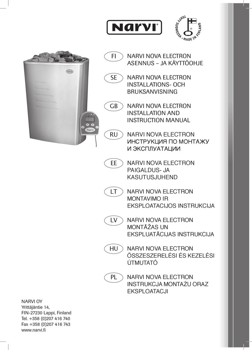
  9. NARVI ELECTRON 450 Quick guide

NARVI ELECTRON 450 Quick guide

INSTALLATION AND INSTRUCTION MANUAL
ELECTRON 450, ELECTRON 600,
ELECTRON 800, ELECTRON 900
GB
1. ONE ELECTRIC SAUNA STOVE PACKAGE COMPRISES:
1. Stove with control equipment
2. Fixing plate + fixing screws
3. Sensing element
4. Control unit + stand
5. Sauna stove installation and instruction manual
2. PRIOR TO INSTALLATION
Perform the following checks:
- The stove is the right size (kW) for the size of the sauna (m3).
- Table 1 shows the sauna volumes for different stove types.
- For every 1 m2of uninsulated brick, tile or glass wall surface in the sauna, increase
the sauna volume by 1.5 m3when choosing the required stove wattage from Table 1.
The sauna volumes indicated in Table 1 are both maximum and minimum values.
Table 1. Installation data for ELECTRON stove
**) See Fig. 1 *) Use a rubber sheathed connection cable
of type H07RN-F or corresponding
Stove type Wattage Sauna Minimum safety distances for stove Amount of Connection*)
stones
Volume Height Sides Front Front From ceiling From floor 400V 3N Fuses
min max min A **) B **) C **) D **) E **)
kW m3m3cm cm cm cm cm cm kg mm2A
ELECTRON 450 4,5 4 7 190 5 5 2 120 5 30 5x1,5 3x10
ELECTRON 600 6 6 9 190 5 8 2 120 5 30 5x1,5 3x10
ELECTRON 800 8 8 13 190 10 10 2 120 5 30 5x2,5 3x16
ELECTRON 900 9 8 15 190 10 10 2 120 5 30 5x2,5 3x16
- Table 1 indicates both the minimum height of the sauna and the minimum safety
distances for the stove.
- Make sure the fixing plate is screwed to a solid base. Wall panelling is not solid
enough, and needs to be reinforced with either additional studs under the panel or
reinforcing boards fixed to the wall studs on top of the panel.
- The stove can also be installed in a wall recess, cf. Fig. 1.
ONLY ONE ELECTRIC STOVE TO BE INSTALLED IN A SAUNA.
3. INSTALLATION:
3.1 Installation of stove and sensing element
- Fasten the fixing plate for the stove on the wall as shown in Fig. 2. Use the 2 screws
included in the delivery.
- Electrical connection of the stove may only be carried out by a qualified electrician
in compliance with valid regulations.
- The connection cable shall be a rubber sheathed cable of type H07RN-F or
corresponding. Cable size and fuse rating as indicated in Table 1.
- Connection of connection cable
- turn the stove bottom up
- open the base of the electrical box
- plug in the connection cable
- There is socket for control unit and
element. Put sockets for connection
plugs. (Fig. 3.1)
- Install cable clamps to electrical box wall.
- replace the base of the electrical box
- turn the stove upright
- Install the sensing element on the wall.
Cf. Fig. 3.2.
- The wiring for the sensing element
can be embedded.
INSTALLATION ON THE WALL:
- Draw in the lugs on the rear side of
the sauna stove through the mounting slots
of the mounting plate on the wall (Fig. 4A).
- Push the upper edge of the mounting plate
between the jacket and upper frame of
the sauna stove and make sure that the
lugs of the stove are wedged into the slots
of the mounting plate on the wall (Fig. 4B).
- Tighten the upper edge of the sauna
stove
with a locking screw (Fig. 4C).
- The stone basket is now locked in the
jacket and on the mounting plate of
the sauna stove.
X
min.250
min.260 121 121 121
250
TYYPPI X min
mm
ELECTRON 450 130
ELECTRON 600 130
ELECTRON 800 180
ELECTRON 900 180
Fig 2. Fixing plate position
A
A
A
C
B
D
min. 5 cm
max 30 cm
Fig 1. Safety distances for ELECTRON stove
Installation of stove
in a wall recess
TYPE
5 cm
Fig. 3.2
Installation of sensing
element on the wall.
The sensor shall be on the
centre line of the stove.
A
B
C
Fig. 4.
Fig 3.1 Connections of circuit plate
Connecting plug
for sensing element
Connecting plug
for control unit
3.2 Installation of control unit
- The control unit can be installed either in the sauna or in the dressing room. In the
sauna the control unit shall be installed at a height of at most 65 cm. Cf. Fig. 5.
- Install the stand for the control unit on the wall and the control unit on the stand. Fig. 5.
- The wiring of the control unit can be shortened. The wire may not be inserted in
the connection box of the stove.
-
Surface installation of control unit into contact box.
Fig. 6.2.
min. 20 cm
max 65 cm
Installation of control unit on
the wall. NOTE! The control unit
must not be installed in a wall
recess.
Fig. 5.
Use little
screwdriver
when you open
the cover. Push
with screwdriver
salients in. In the
picture arrows
shows where
salients are.
Fig. 6.1
Surface installation of control unit
in dressing room.
Fig. 8.
Surface installation of control unit in sauna.
Fig. 7.
Control unit
Fig. 9.
Surface installation of control unit
into contact box.
Fig. 6.2
4. CONTROL UNIT
4.1 Instructions for use of control unit
1. On/Off pushbutton
 • Whenthedisplayisoff,pushingthisbutton willswitchonthecontrolunit
and the stove. The button shall be held down for more than 1 second.
 • Thecontrolunitandthestovecanbe
switched off by pressing the button again
and
holding it down (for more than 1 second).
 • Whenthestoveisswitchedon,thepre-selectiontimewillbedisplayed
(yellow LED is on).
The pre-selection time remains on the display for 5 seconds, and then
the measured temperature is displayed (basic status).
• OtherfunctionsoftheON/OFFpushbutton(helddownforlessthan1second)
First press, adjustment of pre-selection time. Yellow LED flashes.
Second press, adjustment of switching-on time. Yellow LED is on.
Third press, adjustment of target temperature.
Green LED flashes.
Fourth press, display returns to measured temperature.
2. Adjusting times and temperatures
 • Adjustedwith+/-pushbuttonswhenthedesiredfunctionisdisplayed.
3. Light in sauna room
 • Lightisswitchedonandoffbypressingthepushbutton.
4.2 Signal lights
4. Green light = light on in sauna room
5. Green light = on when measured temperature is displayed.
Flashes when target temperature is displayed.
6. Yellow light = on when switching-on time is displayed.
Flashes when pre-selection time is displayed.
7. Red light = on until target temperature is reached for the first time.
4.3 Error messages
 • ERR1=abreakinthesensorcircuit
 • ERR2=ashort-circuitinthesensor
circuit
 • ERR3=abreakintheoverheat
protector’s current circuit
NOTE! If an error message
is displayed, switch off
the sauna stove.
5. TECHNICAL DATA
5.1 Upper board
 • enclosureclass IPX4
 • thecontrolunitcanbe
installed in the sauna or
in the dressing room
6. LOADING OF STONES
- When loading the stones, make sure they do not bend the resistors or obstruct
sufficient circulation of air.
- Do not load the stones too tightly. Over-filling of the stone compartment will
cause overheating of the resistors (= shorter service life) and slower heating up
of the sauna.
- Suitable stones for the stove are 4-7 cm in diameter.
- The stones shall cover the heating resistors completely.
AN UNDER-FILLED STONE COMPARTMENT WILL CAUSE A FIRE HAZARD!
ALWAYS CHECK THE SAUNA BEFORE SWITCHING ON THE STOVE.
4.4 Technical data of control unit
 • Temperatureadjustment
range 40ºC-120ºC
 • Temperaturedisplay20ºC-120ºC
 • Inincrementsof1ºC
 • Pre-selectiontimemax.24h
 • Inincrementsof1/2h
 • Max.PowerOntime4h
5.2 Lower board
 • voltage 400V3N50Hz
 • current 16A
 • stovewattage max.9kW
 • saunalight max.100W
 • enclosureclass IPX4
 • overheatprotection 144ºC
 • Fuse1 1A
Fuse 2 1A
7. VENTILATION IN THE SAUNA
- The ventilation in the sauna should be as efficient as possible in order to ensure
a sufficient oxygen level and freshness of air. We recommend that the fresh air
intake is located near the stove (but not closer than 50 cm).
- The fresh air intake shall be equipped with an adjustable valve.
- The exhaust valve shall be at least twice the size of the fresh air intake. The exhaust
valve can be installed on the opposite wall, at least 20 cm higher than the fresh
air intake.
8. CONSTRUCTION OF SAUNA
- The sauna shall be well heat insulated, particularly the ceiling, where most of
the steam rises. Due to the high level of humidity, the heat insulation should be
covered with moisture-proof material, such as aluminium paper.
Wood should always be used for cladding.
9. PROTECTIVE RAILING
- If required, a protective railing can be built
round the stove. See Fig. 10.
We recommend a wooden railing.
The indicated safety distances to inflammable
structures must be observed.
Improper installation will cause a fire hazard.
L2L1
400V
3N~
NL3 1 U
5321 4 6
X3X2X1N
A2 B2A1 B1
B2B1A2A1
F E D C B A
N N
Fig. 10.

This manual suits for next models

3

Other NARVI Stove manuals

NARVI NM 450 Quick guide

NARVI

NARVI NM 450 Quick guide

NARVI GREENLINE WT NM 12-25 Operating instructions

NARVI

NARVI GREENLINE WT NM 12-25 Operating instructions

NARVI SMOOTH 9kW Quick guide

NARVI

NARVI SMOOTH 9kW Quick guide

NARVI AITO Aitokiuas AK-68 Operating instructions

NARVI

NARVI AITO Aitokiuas AK-68 Operating instructions

NARVI STONY 18 Setup guide

NARVI

NARVI STONY 18 Setup guide

NARVI STONY 18 Setup guide

NARVI

NARVI STONY 18 Setup guide

NARVI 30 Series Operating instructions

NARVI

NARVI 30 Series Operating instructions

NARVI NOVA ELECTRON Series Quick guide

NARVI

NARVI NOVA ELECTRON Series Quick guide

NARVI NME 450 User manual

NARVI

NARVI NME 450 User manual

NARVI NARVI-ULTRA Quick guide

NARVI

NARVI NARVI-ULTRA Quick guide

NARVI Softy 4,5kW User manual

NARVI

NARVI Softy 4,5kW User manual

NARVI ULTRA BIG N18 Quick guide

NARVI

NARVI ULTRA BIG N18 Quick guide

Popular Stove manuals by other brands

Hunter Stoves Hawk User instructions

Hunter Stoves

Hunter Stoves Hawk User instructions

Dovre 2510SEC/D Installation instructions & operating manual

Dovre

Dovre 2510SEC/D Installation instructions & operating manual

MCZ MUSA COMFORT AIR MATIC 14 M1 Use and installation  manual

MCZ

MCZ MUSA COMFORT AIR MATIC 14 M1 Use and installation manual

Sierra Woodstoves Cricket 5300 Installation and operating instructions

Sierra Woodstoves

Sierra Woodstoves Cricket 5300 Installation and operating instructions

GALLERY FIREFOX 5 ECO INSTALLATION MANUAL AND USER OPERATING INSTRUCTIONS

GALLERY

GALLERY FIREFOX 5 ECO INSTALLATION MANUAL AND USER OPERATING INSTRUCTIONS

Harman Stove Company TLC 2000 Stove Operator's manual

Harman Stove Company

Harman Stove Company TLC 2000 Stove Operator's manual

FOTILE GAG76202 user manual

FOTILE

FOTILE GAG76202 user manual

Saltfire ST4 Installation and operating instructions

Saltfire

Saltfire ST4 Installation and operating instructions

Arada Ecoburn S3 Fittings guide

Arada

Arada Ecoburn S3 Fittings guide

Coleman PEAK 1 user manual

Coleman

Coleman PEAK 1 user manual

Lincar MONELLINA 176AN PLUS Using instructions and maintenance

Lincar

Lincar MONELLINA 176AN PLUS Using instructions and maintenance

Comfort Glow SL30NT Series OWNER'S OPERATION AND INSTALLATION MANUAL

Comfort Glow

Comfort Glow SL30NT Series OWNER'S OPERATION AND INSTALLATION MANUAL

Breckwell P241 owner's manual

Breckwell

Breckwell P241 owner's manual

COUNTRY FLAME TECHNOLOGIES CF-04 Installation, operation and maintenance manual

COUNTRY FLAME TECHNOLOGIES

COUNTRY FLAME TECHNOLOGIES CF-04 Installation, operation and maintenance manual

Kenyon 126 Instructions and parts list

Kenyon

Kenyon 126 Instructions and parts list

Hunter Stoves HUNTER HAWK 4 MKII User instructions

Hunter Stoves

Hunter Stoves HUNTER HAWK 4 MKII User instructions

Wamsler WP2-8 Installation and operating instructions

Wamsler

Wamsler WP2-8 Installation and operating instructions

Uniflame GCT903W owner's manual

Uniflame

Uniflame GCT903W owner's manual

manuals.online logo
manuals.online logoBrands
  • About & Mission
  • Contact us
  • Privacy Policy
  • Terms and Conditions

Copyright 2025 Manuals.Online. All Rights Reserved.