Somatex Maco Multi Matic User manual

SOMATEC
Sondermaschinen-Vorrichtungen
Komponenten für Maschinenbau
Klaus Mayer • Gewerbestraße 19 •D-88636 Illmensee • Telefon +49(0)7558/9214-
0
info@somatec-mb.de • www.somatec-mb.de • Telefax +49(0)7558/674
®
BETRIEBSANLEITUNG
USER MANUAL
UNI – POWER
Beschlagstanze Maco Multi Matic
Fitting cropper Maco Multi Matic
Anbau rechts und links
Assembly right and left
Betriebsanleitung vor Inbetriebnahme lesen und beachten!
Please read and follow the User Manual before commissioning!

2
Inhalt
1SICHERHEITSHINWEISE....................................................................................................................... 3
1.1 WARNHINWEISE UND SYMBOLE ........................................................................................................... 3
1.2 BESTIMMUNGSGEMÄßE VERWENDUNG................................................................................................. 3
1.3 PFLICHTEN DES BETREIBERS................................................................................................................. 3
1.4 ANFORDERUNGEN AN DAS PERSONAL .................................................................................................. 4
2TECHNISCHE DATEN.............................................................................................................................. 4
3MONTAGE.................................................................................................................................................. 5
3.1 MONTAGE DES GERÄTES ...................................................................................................................... 5
3.2 ANSCHLUSS PNEUMATIK ...................................................................................................................... 5
4BEDIENUNG & WERKZEUGWECHSEL & WARTUNG ................................................................... 5
4.1 BEDIENUNG .......................................................................................................................................... 5
4.2 WARTUNG ............................................................................................................................................ 6
4.3 STEMPEL-&MATRIZENWECHSEL......................................................................................................... 7
4.4 BESCHREIBUNG WERKZEUG UND ESRATZTEILLISTE............................................................................. 9
5FEHLERSUCHE....................................................................................................................................... 10
5.1 FEHLERSUCHE AM STANZZYLINDER UND WERKZEUG ........................................................................ 10
ERSATZTEILLISTE .................................................................................................................................11
11 EG-KONFORMITÄTSERKLÄRUNG................................................................................................... 21
Contents
6TIPS ON SAFETY .................................................................................................................................... 12
6.1 WARNING TIPS AND SYMBOLS ............................................................................................................ 12
6.2 INTENDED APPLICATION..................................................................................................................... 12
6.3 OBLIGATIONS OF THE OPERATOR........................................................................................................ 12
6.4 REQUIREMENTS OF PERSONNEL .......................................................................................................... 13
7TECHNICAL DATA................................................................................................................................. 13
8ASSEMBLY............................................................................................................................................... 14
8.1 DEVICE ASSEMBLY............................................................................................................................. 14
8.2 PNEUMATIC CONNECTION .................................................................................................................. 14
9OPERATION & TOOL REPLACEMENT & MAINTENANCE......................................................... 14
9.1 OPERATION......................................................................................................................................... 14
9.2 MAINTENANCE ................................................................................................................................... 15
9.3 PUNCH AND DIE REPLACEMENT .......................................................................................................... 16
9.4 TOOL DESCRIPTION AND SPARE PART LIST ......................................................................................... 18
10 TROUBLESHOOTING............................................................................................................................ 19
10.1 TROUBLESHOOTING THE TOOL AND CROPPING CYLINDER................................................................... 19
SPARE PART LIST PRESSURE AMPLIFIER.................................................................................................20
11 EC CONFORMITY DECLARATION.................................................................................................... 21
3
1 Sicherheitshinweise
Die Betriebsanleitung muss ständig am Einsatzort des Gerätes verfügbar sein.
Die Betriebsanleitung ist von jeder Person zu lesen und anzuwenden, die mit den Arbeiten an der
oder mit der Beschlagstanze beauftragt sind.
1.1 Warnhinweise und Symbole
Diese Betriebsanleitung enthält Hinweise auf mögliche Gefahren, die bei unsachgemäßem Einsatz
der Beschlagstanze auftreten können. Diese Hinweise sind mit einem Signalwort (Warnung oder
Vorsicht) und einem Piktogramm gekennzeichnet.
Folgende Gefahrhinweise werden unterschieden:
Dieses Symbol bedeutet, dass bei Missachtung ein
Personen- oder Sachschaden entstehen kann.
Dieses Symbol bedeutet, dass bei Missachtung ein schwerer
Personen- oder Sachschaden entstehen kann.
1.2 Bestimmungsgemäße Verwendung
Die Beschlagstanze UNI – POWER findet Anwendung zum Ablängen der Stulpschienen und
Schubstangen in einem Arbeitsgang von Maco– Fensterbeschlägen und darf auch
ausschließlich nur für diese Anwendung verwendet werden.
Das Gerät ist nach dem Stand der Technik und den anerkannten sicherheitstechnischen Regeln
gebaut.
Dennoch können bei Fehlbedienung oder Missbrauch des Gerätes Gefahren für Leib und Leben des
Benutzers oder Dritter bzw. Beeinträchtigungen des Gerätes oder andere Sachschäden entstehen.
Das Gerät darf nur in technisch einwandfreiem Zustand sowie bestimmungsgemäß, sicherheits- und
gefahrenbewusst unter Beachtung der Betriebsanleitung genutzt werden. Insbesondere müssen
Störungen, die die Sicherheit beeinträchtigen können, umgehend beseitigt werden.
Zur bestimmungsgemäßen Verwendung gehören unter anderem das Beachten der Betriebsanleitung
und die Einhaltung der Inspektions- und Wartungsarbeiten.
1.3 Pflichten des Betreibers
Die Beschlagstanze UNI - Power wurde unter Berücksichtigung einer Gefahrenanalyse und nach
sorgfältiger Auswahl der einzuhaltenden harmonisierten Normen, sowie weiterer technischer

4
Spezifikationen konstruiert und gebaut. Sie entspricht damit dem Stand der Technik und gewährleistet
ein Höchstmaß an Sicherheit.
Diese Sicherheit kann in der betrieblichen Praxis jedoch nur dann erreicht werden, wenn alle dafür
erforderlichen Maßnahmen getroffen werden. Es unterliegt der Sorgfaltspflicht des Gerätebetreibers,
diese Maßnahmen zu planen und ihre Ausführung zu kontrollieren.
Das Gerät muss auf jeden Fall vor der Inbetriebnahme auf
einen dafür geeigneten Tisch aufgeschraubt werden.
Der Betreiber des Stanzgerätes muss den Bedienern diese Betriebsanleitung zugänglich machen und
sich vergewissern, dass Sie sie gelesen und verstanden haben. Erst dann darf man die Stanze in
Betrieb nehmen.
Die Betriebsanleitung muss ständig am Einsatzort der Beschlagstanze verfügbar sein.
Die Zuständigkeiten an und mit der Beschlagstanze müssen klar festgelegt und eingehalten werden.
Unklare Kompetenzen können die Sicherheit der Benutzer gefährden.
1.4 Anforderungen an das Personal
Alle Arbeiten wie z.B. Montage, Installation, Inbetriebnahme, Betrieb, Fehlersuche, Beseitigung von
Störungen, Wartung oder Instandhaltung dürfen ausschließlich von Fachpersonal durchgeführt
werden.
Das Fachpersonal muss für die sichere Ausführung der Arbeiten die nötigen Kompetenzen aufweisen
und im Umgang mit der Beschlagstanze geschult und unterwiesen sein, insbesondere über die
bestehenden Gefahren, Schutzmaßnahmen und im sicherheitsgerechten Verhalten.
2 Technische Daten
Betriebsdruck 5 – 8 bar
Schnittkraft
Krafthub
3,09 KN bei 6 bar 13mm
Luftverbrauch
pro Hub Bei 6 bar 5,3NL / Hub
Übersetzungs-
verhältnis 1 : 10,25
Gewicht Ca.10,6Kg
Verwendete
Öl - Sorte Esso – Univis N46
Nennweite für
Luftanschluss 7mm ¼“
5
3 Montage
3.1 Montage des Gerätes
Achten Sie auf eine gute und sichere Befestigung der Beschlagstanze!
3.2 Anschluss Pneumatik
Schalten Sie vor Installations- oder Wartungsarbeiten
folgende Energiequellen aus:
•Luftzufuhr
Die Beschlagstanze kann über ein 5/2 handbetätigtes bzw. ein 5/2 fußbetätigtes Steuerventil ohne
zusätzliche Sicherheitseinrichtungen betrieben werden.
Zum Schutz des Stanzzylinders gegen Verunreinigungen, ist ein Filterregler erforderlich. Auf ein
regelmäßiges Ablassen des Kondenswassers und ein Verschmutzen des Filters ist zu achten!
Bei mitgeliefertem Zubehör Stanze wie folgt anschließen:
-Ausgang am Filterregler mit Anschluss 1 am Fußventil verbinden
-Ausgang 2 am Fußventil mit Rückhub Stanze verbinden
-Ausgang 4 am Fußventil mit Vorhub Stanze verbinden
-Eingang Filterregler 1/4“ mit Druckluftversorgung verbinden
-Zum Anschließen den mitgelieferten Pneumatikschlauch verwenden
-Anschlüsse Stanze siehe Seite 14
4 Bedienung & Werkzeugwechsel & Wartung
4.1 Bedienung
Verge
wissern Sie sich, dass sich das Gerät in
ordnungsgemäßem Zustand befindet, und dass sich keine
Personen im Gefahrenbereich aufhalten können.
•Achten Sie auf eine sichere Befestigung der Beschlagstanze auf einem Tisch, in geeigneter
Arbeitshöhe, jedoch nicht über einem Meter.
•Achten Sie bei der Befestigung der Stanze darauf, dass die Stanzabfälle frei herunterfallen
können. (Abfallstau kann zum Werkzeugbruch führen)
6
•Achten Sie beim Stanzen darauf, dass keine Personen durch abspritzende Stanzabfälle
getroffen werden können. (Falls erforderlich Spritzschutz anbringen)
•Achten Sie beim Stanzen mit gespreiztem Beschlag darauf, dass Sie den Beschlag nicht im
Bereich der Aufspreizung festhalten. (Verletzungsgefahr beim Stanzvorgang durch
Zusammendrücken der beiden Beschlagsteilen)
•Beim Arbeiten mit der Beschlagstanze ist eine Schutzbrille zu tragen
4.2 Wartung
•1. Die Beschlagstanze UNI – POWER arbeitet größtenteils Wartungsfrei, zu beachten ist
lediglich eine regelmäßige, ihrer Druckluftqualität angepasste, Kontrolle des Filterreglers,
denn die Verschmutzung des Filterelementes kann zur Verlangsamung des Stanzvorganges
führen. Ebenso kann bei längerem Nichtablassen des Kondensates der Stanzzylinder
verschmutzen und dadurch schneller verschleißen.
•2. Ein weiterer Punkt der Wartung ist, dass am Stanzzylinder von Zeit zu Zeit Öl nachgefüllt
werden muss. Der Zeitpunkt der Ölnachfüllung ist dadurch erkennbar, dass der Stanzzylinder
nicht mehr seinen vollen Stanzhub ausfahren kann bzw. den Beschlag nicht mehr vollständig
abschneiden oder die Schraubensenkung nicht ausprägt werden kann. Dann wird wie
nachfolgend beschrieben vorgegangen.
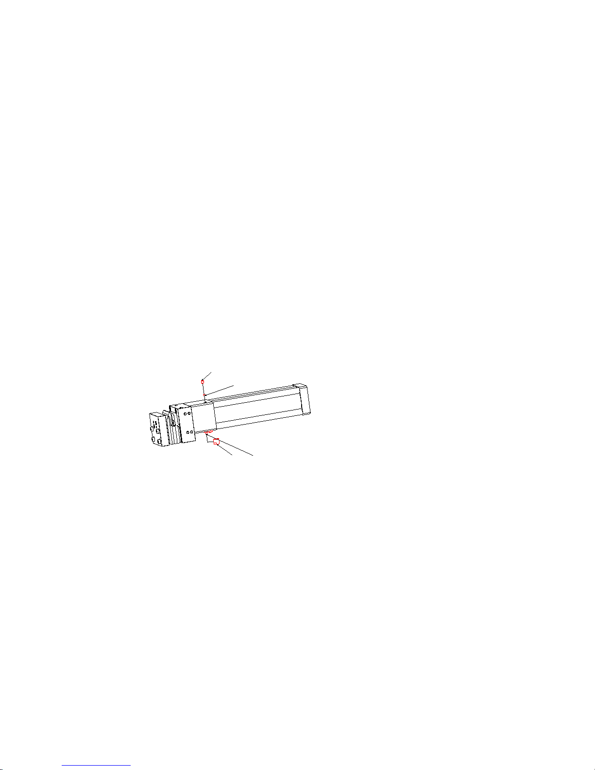
51
55
47
50
Schutzkappe 51 vom Füllnippel 47 abschrauben und mit einer Stoßölpresse solange Öl
einfüllen, bis sich der Schneidstempel 9 mit Lochstempel 10 minimal nach vorne bewegt.
Dabei ist zu beachten, dass dem Stanzzylinder nicht die Druckluft abgeschaltet wird und er
sich in seiner Grundstellung befindet. Ebenso ist zu beachten, dass die Ölpresse keinerlei Luft
mitbefördert. Sollte versehentlich zuviel Öl eingefüllt worden sein, bzw. im Zylinder nach dem
Füllvorgang sich Luft im Ölraum befinden, kann am Zylinder durch öffnen der Schraube 55 Öl
abgelassen bzw. entlüftet werden. Dabei ist unbedingt zu beachten, dass der Ölraum
unter Druck steht und somit das überschüssige Öl schnell entweicht bzw. die sich
unter der Schraube 55 befindende Kugel 50 verloren gehen kann. ( Achtung beim
Ölablassen unbedingt eine Schutzbrille tragen!)
•3. Die Wartung am Werkzeug bezieht sich auf ein regelmäßiges säubern und einölen der
Schneidstempel Pos. 7, 9, und 10 mit einem dünnflüssigen Scheidöl bzw. Schneidölspray.
•4. Ein Ölwechsel ist nicht zwingend notwendig, kann jedoch wie nachfolgend beschrieben
durchgeführt werden: Verschlussschraube 55 mit der Kugel 50 entfernen die Beschlagstanze
7
mit der nun offenen Bohrung über einen Behälter zum Ölauffangen legen und den Stanzhub
einmal ohne Beschlag langsam durchführen. Das alte Öl wurde nun aus dem Zylinder
gepresst und er kann nun wie in Punkt 2 beschrieben, wieder gefüllt werden. (Achtung, bitte
nicht ohne Schutzbrille arbeiten, auf ein luftfreies Öleinfüllen achten und das Altöl
umweltgerecht entsorgen )
•5. Stanzzylinder entlüften: Sollten Sie beim Füllen dennoch einmal Luft in den Zylinder
bekommen haben, können Sie diese durch öffnen der Schraube 55, herausnehmen der Kugel
50 und anschließendes Nachfüllen am Füllnippel 47 wieder herauspressen. Dabei ist
solange Öl einzufüllen bis keine Luftblasen mehr an der gegenüberliegenden Seite mehr
ausströmen. Vorteilhaft ist dabei auch, wenn man die Stanze in seiner Achse leicht bewegt
damit sich die Luftblasen leichter im Bereich der Entlüftungsbohrung ansammeln können.
4.3 Stempel- & Matrizenwechsel
Schalten Sie vor dem Lösen bzw. Anziehen der Schrauben
Pos. 13 die Druckluftversorgung zum Stanzzylinder ab!
Achtung: Betätigen des Stanzzylinders mit nicht festgezogenen
Schrauben kann ihn beschädigen.
•1. Zum Wechseln der Schneidstempel Pos. 7 und 9 und des Lochstempels Pos. 10 sowie der
Matrize Pos. 2, trennen Sie den Stanzzylinder vom Druckluftnetz, um ein unbeabsichtigtes
Auslösen des Stanzvorganges zu vermeiden. Ein Auslösen des Stanzvorganges bei gelösten
Schrauben Pos. 13 zerstört die Gewinde im Zylinderkopf.
•2. Schrauben Pos. 13 herausdrehen.
•3. Gegenlager Pos. 11 abziehen.
•4. Matrizen- mit Führungsteil Pos. 2, 3 und 4 abziehen.
•5. Stanzzylinder wieder am Druckluftnetz anschließen und den Stanzvorgang auslösen und
halten, um beim Herausdrehen der Schrauben Pos. 14 ein Verdrehen des Pressstößels zu
vermeiden.
•6. Schrauben Pos. 14 unter Beachtung von Punkt 5 herausdrehen.
•7. Verschleißteile Pos. 9, 10, 16, und 18 nach Bedarf tauschen und unter Beachtung von
Punkt 5 wieder zusammenbauen. Dabei sind die Schrauben Pos. 14 mit 19 Nm anzuziehen.
•8. Zum Wechseln des Schneidstempels Pos. 7 die Passstifte Pos. 15 herauspressen und die
Schrauben Pos. 14 herausdrehen. Der Zusammenbau erfolgt in umgekehrter Reihenfolge, die
Schrauben Pos. 14 leicht eindrehen Passstifte einpressen und die Schrauben Pos. 14 mit 19
Nm anziehen
•8. Der Matrizenteil Pos. 2, 3 und 4 kann entweder als Ganzes getauscht werden, oder durch
ein Zerlegen nur das verschlissene Teil.
•9. Zum Zerlegen des Matrizenteiles werden die Schrauben Pos. 5 herausgedreht, die
Passstifte Pos. 22, falls vorhanden, ausgepresst. Danach kann das Matrizenteil mit zwei
Schrauben M8 und zwei Schrauben M10 durch ein Gegeneinanderdrehen der Schrauben

8
zerlegt werden. Es ist jedoch darauf zu Achten, dass dies gleichmäßig geschieht, um ein
Beschädigen der Führungsbuchse Pos. 8 zu vermeiden.
•10. Zusammenbau des Werkzeuges: Beim Zusammenbau des Matrizenteiles werden zuerst
die Führungsbuchsen Pos. 8 im Lagerteil Pos. 3 eingepresst. Danach wird die Matrize Pos. 2
auf die Führungsbuchsen aufgeschoben, und das Lagerteil Pos. 4 aufgepresst, danach
werden die Schrauben Pos. 5 eingeschraubt und mit 23 Nm angezogen. Vor dem
Aufschieben des Matrizenteils auf die Führungswellen Pos. 12, die Führungsbuchsen auf
Leichtgängigkeit prüfen und bei Bedarf nacharbeiten. Die Stempelführung und
Führungsbuchsen mit Kupferpaste leicht einstreichen. Danach den Matrizenteil auf die
Führungswellen aufschieben. Nach dem Aufschieben des Matrizenteiles den Schneidstempel
Pos. 9 in die Führungsplatte Pos. 4 durch mehrmaliges betätigen des Stanzzylinders
vorsichtig ohne die Führung zu beschädigen einfahren. Danach das Gegenlager Pos. 11 mit
der Feder Pos. 6 und den Schrauben Pos. 13 gleichmäßig auf die nun wieder vom
Druckluftnetz getrennte Stanze aufschrauben und die Schrauben Pos. 13 mit 23 Nm
anziehen.

9
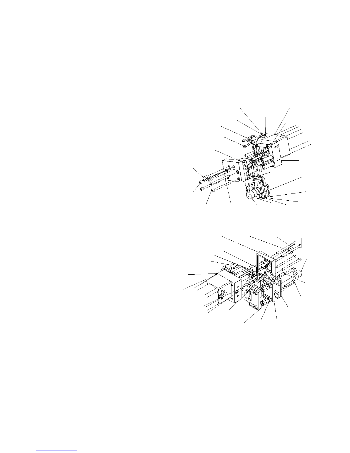
4.4 Beschreibung Werkzeug/ Ersatzteilliste
Achtung: Bei Ersatzteilbestellung, die Anbautype der Stanze (ob Anbau rechts oder links mit)
angeben!
14
2
8
3
6
11
13
14
15
7
916
10 18 1
4
5
21
12
17
5
22
6
13
14
15
11
7
21
3
19
482
9
1
10
20
12
OBJEKT ANZAHL
BAUTEILNUMMER
1
1
05 05 00 1000 Druckübersetzer
2
1
05 05 01 0001 Matrize Maco
3
1
05 05 01 0002 Lagerteil Matrize hinten
4
1
05 05 01 0003 Lagerteil Matrize vorne
5
2
DIN 912 M8x50.
6
1
FIBROFLEX-Rundfeder
D32-13,5 23lang 80ShoreA
7
1
05 05 01 0006 Schneidstempel Maco
8
2
Führungsbuchse D16-22 40 lang
mit Festschmierstoff
9
1
05 05 01 0007 Schneidstempel Maco
10
1
05 05 01 0008 Lochstempel Maco
11
1
05 05 01 0004 Gegenlager
12
4
05 05 01 0005 Führungs-Stehbolzen
13
4
DIN 912 M8x110.
14
4
DIN 912 M6x20.
15
3
DIN 6325-A 6x20-St.
16
1
05 05 00 0013 Abdrückbolzen
17
1
05 05 00 0014 Scheibe
18
1
FIBROFLEX-Rundfeder
D12 12lang 90ShoreA
19
1
05 05 01 0009 Fibroeinlage Maco
20
1
05 05 01 0010 Gewindescheibe M5
21
1
DIN 7991 M5x10.
22
2
DIN 6325-A 8x40-St.

10
27
8
2
Vorhub Rückhub
29
5 Fehlersuche
5.1 Fehlersuche an Werkzeug und Stanzzylinder
Fehler am Werkzeug
Ursache
Beseitigung
Beschlag lässt sich auf der
Stulpschienenseite nur schwer oder
gar nicht mehr einlegen
Im Übersetzerzylinder befindet sich
zuviel Öl
Öl wie unter 4.2 Kapitel 2
beschrieben ablassen
Beschlag lässt sich auf der
Schubstangenseite nur schwer oder
gar nicht mehr einlegen
Fibroflex– Rundfeder ist
verschlissen, bzw. es müssen die
Stempelführungen geschmiert
werden
Fibroflex – Rundfeder tauschen 4.3
bzw. Stempel
führungen schmieren
4.3 Kapittel10
Beschlag wird nicht mehr
abgeschnitten oder die Senkung ist
nicht mehr ausgeprägt.
Im Übersetzerzylinder ist zuwenig Öl
oder der Betriebsdruck ist zu niedrig
Öl wie unter 4.2 Kapitel 2
beschrieben nachfüllen,
bzw. Betriebsdruck kontrollieren.
Unsauberes Stanzbild; keine
Lochung
Stempel und Matrizenverschleiß,
bzw. Lochstempelbruch.
Stempel bei Bruch wie unter 4.3
beschrieben wechseln bzw. bei
Verschleiß der Teile nachschleifen
Fehler am Stanzzylider
Ursache
Beseitigung
Beschlag wird nicht mehr
abgeschnitten oder die Senkung ist
nicht mehr ausgeprägt, dabei
entweicht ständig Luft aus Pos. 2
Kolbendichtung Pos. 1.8 aus der
Ersatzteilliste ist verschlissen
Dichtungswechsel: Durch heraus-
drehen der Hohlschrauben Pos. 29
k
ann der hintere Teil des
Stanzzylinders zerlegt werden.
Anschließend Stanze wie unter
Wartung 4.2 Pos.4 & 5 beschrieben
wieder füllen und entlüften.
Öl läuft nach ständigem Ölverlust
aus dem Entlüftungsfilter Pos. 2
Kolbenstangendichtung Pos. 1.17
aus der
Ersatzteilliste ist
verschlissen
Zerlegen der Stanze wie oben
beschrieben, danach Mutter Pos.
1.15 zum Wechseln der Dichtung
Pos. 1.17 abschrauben;
Zusammenbau der Stanze wie oben.
Öl bzw. Luft kommt aus der Bohrung
Pos. 8 am Pressstößel bzw. bläst
Luft seitlich am Pressstößel vorbei.
Kolbendichtungen Pos. 1.8 & 1.9
bzw. Stangendichtung Pos. 1.3, aus
der Ersatzteilliste sind verschlissen
Dichtungswechsel: Durch heraus-
drehen der Hohlschrauben Pos. 27
kann das Vorderteil des Stanz-
zylinders zerlegt werden. Beim
Zusammenbau, die Schrauben Pos.
27 mit 23 Nm anziehen.
Anschließend Stanze wie unter
Wartung 4.2 Pos.4 & 5 beschrieben
wieder füllen und entlüften.

11
1.9
1.8
1.5
1.10
1.23
1.18
1.21
1.20
1.19
1.22
1.7
1.1
1.3
1.11
1.16
1.17
1.15
1.9
1.8
1.5
1.4
1.2
1.6
Ersatzteilliste Powerzylinder
Achtung:
Bei einem Dichtungswechsel empfiehlt es sich bei älteren Stanzzylindern den kompletten Satz zu
tauschen, denn beim Wiedereinbau der alten Dichtungen besteht die Gefahr der Undichtigkeit.
Außerdem sollten Reparaturarbeiten nur von Personal mit den nötigen fachlichen Kompetenzen
ausgeführt werden.
Im Zweifelfalle sollten Sie den Stanzzylinder zum Dichtungswechsel bei der nächsten Serviceadresse
einschicken!
OBJEKT
ANZAHL
BAUTEILNUMMER
1
1
05 05 00 1000 Druckübersetzer
1.1
1
05 05 00 0001 Zylinderkopf - Beschlagstanze
1.2
1
O - Ring 40 x 2,5
1.3
1
DIN 3760 A (rechts) A-40x52x7 - NBR
1.4 1 DU-Buchse BK-I 4020
1.5
2
O-Ring 74x3
1.6
1
05 05 00 0002 Kolbenstange D40
1.7
1
05 05 00 003 Übersetzerkolben
1.8
2
Z8A8070N3580 80x70x4,25
1.9 2 F3-5,6x2,5 Kolbenführungsband D80
1.10
1
B7 8010 P5008 80x70x6,7
1.11
1
O - Ring 24 x 2,5
1.12 1 05 05 00 0012 Übersetzerzylinder
1.13
1
05 05 00 0004 Druckrohr
1.14
1
O - Ring 44,12 x 2,62 N552 - 90 für D45
1.15 1 05 05 00 0005 Mutter Druckrohr
1.16
1
DU-Buchse 25 x 28 x 25
1.17
1
B3 2532P5008 25 x 33 x 5,7
1.18 1 05 05 00 0008 Kolbenstange
1.19
1
05 05 00 0006 Kolben D79,6 x 16 Kolben
1.20
1
05 05 00 0007 Dämpfung Fibro 80 Shohre
1.21
1
Mutter DIN 936 17H
1.22
1
05 05 00 0010 Profilrohr 80x2,5 289 lang
1.23
1
05 05 00 0009 Deckel
1.24
2
DIN 912 M8x50.
1.25
2
DIN 912 M8x60.
1.26
4
05 05 00 0011 Zuganker
1.27
4
Hohlschraube M8
1.28
1
Füllnippel M12x1 mit Scheibe und Verschlußkappe1
1.29
1
Entlüftungsventil R1-4
1.30
2
Kugel 5,5
1.31
2
DIN 913 M8x8.

12
6 Tips on safety
The User Manual must always be available where the device is installed.
The User Manual must be read and used by each person who works on or with the fitting punch.
6.1 Warning tips and symbols
This User Manual contains notes on possible hazards, which could arise with improper use of the
fitting punch. These notes are flagged with a keyword (Warning or Attention) and a pictogram.
It is differentiated between the following hazard symbols:
This symbol means that harm / damage could occur to
people or materials in case of misuse.
This symbol means that severe harm / damage could occur
to people or materials in case of misuse.
6.2 Intended Application
The fitting punch UNI – POWER is used for trimming the shielding bars and connecting rods in
a single operation of Maco window metal fittings, and may be used exclusively for this
application.
The device is manufactured using state-of-the-art technology and the accepted rules of safety.
Nonetheless, there could be hazards for people and material in case of misuse of the device, both for
the operator or a third party and / or damage to the device or other materials.
The device may only be used when it is in a proper condition and also for the intended application,
with an awareness of the safety and hazards associated with its use as given in the User Manual. In
particular, faults, which could affect the safe operation of the device, must be immediately rectified.
By intended application is meant, amongst others, following the instructions given in the User Manual
and complying with the inspection and maintenance requirements.
6.3 Obligations of the operator
The fitting punch UNI - Power has been designed and manufactured taking the hazard analysis into
account, and after careful selection of the harmonized standards, as well as other technical
specifications, to be complied with. It thus corresponds to the state-of-the-art technology, and
guarantees the highest possible degree of safety.

13
However, this level of safety can be achieved in operational practice only when all measures required
for this purpose have been put in place. The onus of planning the required measures and checking
their implementation lies with the operator of the device.
Prior to commissioning, the device must be fixed to a
suitable table with screws.
The user of the punch device must ensure that this User Manual is accessible to all persons using the
device, and must make sure that they have read and understood the same. Only then may one put the
punch into operation.
The User Manual must always be available at the place where the fitting punch has been installed.
The responsibilities pertaining to the fitting punch must be clearly determined and complied with.
Inadequate competencies could endanger the safety of the users.
6.4 Requirements concerning personnel
All tasks such as, for example, assembly, installation, commissioning, operation, troubleshooting,
maintenance or repair may be carried out only by authorized technical personnel.
The technical personnel must have the required competence to carry out the tasks safely, and must
be adequately trained on the fitting punch, particularly with respect to the hazards and safety
measures with respect to working safely with the fitting punch.
7 Technical Data
Operating pressure 5 – 8 bar
Working stroke cutting
force
3.09 KN at 6 bar 13mm
Air consumption
per stroke At 6 bar 5.3NL / stroke
Conversion ratio 1 : 10.25
Weight Approx.10.6Kg
Type of oil used Esso – Univis N46
Nominal width for
Air connection 7mm ¼“

14
8 Assembly
8.1 Device Assembly
Please ensure that the fitting punch is secured properly!
8.2 Pneumatic Connection
Please switch off the following energy sources prior to
undertaking installation or maintenance:
•Air supply
The fitting punch can be operated by means of a 5/2 hand-driven and / or a 5/2 foot-driven control
valve without additional safety devices.
A filter regulator is necessary to protect the cropping cylinder from dirt. Attention must be paid to
regular discharge of condensed water and dirt collection on the filter!
When accessories have been supplied please connect the cropper as follows:
-Connect the output at the filter regulator with interface 1 of the foot valve
-Connect output 2 of the foot valve with the cropper back stroke
-Connect output 4 of the foot valve with the cropper front stroke
-Connect input of the filter regulator 1/4“ with compressed air supply
-Use the pneumatic pipe supplied to connect
-For connections of the cropper refer to page 14
9 Operation & tool replacement & Maintenance
9.1 Operation
Please make sure that the device is in proper working
condition and that nobody can stand in the hazardous
area.
•Please ensure that the fitting cropper is fixed scurely on a table at a suitable height, but,
however, not beyond one meter.
•Please note while fixing the cropper that the residue of the cropped material can fall down
without obstruction. (Blockage of the residue can lead to breakage of the tool)

15
•While cropping please pay attention to ensure that the residue material discarded does not fall
on any people in the vicinity. (If necessary, please make arrangements to provide protection
against spraying of the residue material)
•Please take care when cropping with expanded fitting that you do not hold the fittings in the
region in which they spread out. (Hazard of injury during the punching process while pressing
the two parts of the fitting)
•When working with the fitting cropper, please wear safety goggles
9.2 Maintenance
•1. The fitting cropper UNI – POWER works primarily without the need for maintenance. What
must be paid attention to is merely regular checking of the filter regulator based on the
compressed air quality, since dirt on the filter element could lead to a slowdown in the
cropping process. Similarly, if the condensate is not discharged regularly, the cropping
cylinder could get dirty and thus wear out faster.
•2. Another point with respect to maintenance is regular topping up of oil in the cropping
cylinder. One can see when oil needs to be topped up when the cropping cylinder cannot
move out to its complete stroke or the screw sinking cannot be spread. Under these
circumstances, the following needs to be done.
51
55
47
50
Unscrew the protective cap 51 from the nipple 47 and fill up oil using an oil press till such time
that the cutting punch 9 moves slightly with the drill punch 10. It must be paid attention to here
that the compressed air supply to the cropping cylinder is not switched off and that it is in its
base position. Similarly, care must be taken to ensure that the oil press does not suck in any
air. If, inadvertently, too much oil has been filled up, and/or there is air trapped in the cylinder
after filling up the oil, then the oil can be discharged or air removed by opening the screw 55.
However, when doing so, it must be noted that the oil remains under pressure and the
excess oil discharges quickly and / or the ball 50 under the screw 55 can get lost.
(Attention: Please wear safety goggles when releasing the oil!)
•3. The maintenance of the tool consists of regular cleaning and oiling of the cutting punch
(pos. 7, 9 and 10) with a low viscosity cutting oil or cutting oil spray.
•4. Changing the oil is not mandatory, and can be carried out as described below: Remove the
locking screw 55 with the ball 50, place the fitting cropper with the open bore over a container
to collect falling oil, and move the fitting cropper once slowly. The old oil is now pressed out of

16
the cylinder, and it can be filled up again as described under point 2. (Attention, please do
not work without safety goggles, take care that oil is filled without any air seepage and
that the used oil is disposed off in an environment-friendly manner)
•5. Vent the cropping cylinder: Should you have some air leaked into the cylinder while filling in
oil, you can remove it by opening the screw 55, removing the ball 50 and finally refilling at the
niple 47. Here, oil must be filled in until no more air bubbles appear at the other end. It is also
advantageous to move the punch slightly in its axis so that the air bubbles can collect easily in
the area of the ventilation bore.
9.3 Punch and die replacement
Please switch off the compressed air supply to the cropping
cylinder prior to lossening or removing the screws (pos. 13)!
Attention: Moving the cropping cylinder with untightened screws
could damage it.
•1. To replace the cutting punch (pos. 7 and 9) and the piercing punch (pos. 10) as also the die
(pos. 2), isolate the cropping cylinder from the compressed air network, so as to avoid an
inadvertent cropping action. The cropping action with untightened screws (pos. 13) damages
the threads in the cylinder head.
•2. Remove the screws (pos. 13).
•3. Pull out the counter bearing (pos. 11).
•4. Remove the die with the guide (pos. 2, 3 and 4)..
•5. Connect the cropping cylinder to the compressed air network and initiate the cropping
action and hold it, in order to avoid turning of the press slide while removing the screws (pos.
14).
•6. Remove the screws (pos. 14) keeping pos. 5 in mind.
•7. Replace the wear-out parts (pos.s 9, 10, 16 and 18) if required, and reassemble them
keeping point 5 in mind. For this, the screws (pos. 14) must be tightened with a torque of 19
Nm.
•8. To replace the cutting punch (pos. 7), press the dowel pin and remove the screws (pos. 14).
The assembly is to be done in the reverse order, turn the screws (pos. 14) slightly, press in
the dowel pin and tighten the screws (pos. 14) with a torque of 19 Nm
•8. The die (pos. 2, 3 and 4) can either be replaced completely, or only the worn out part after
disassembling the same.
•9. In order to disassemble, the die the screws (pos. 5) are removed, and the dowel pin (pos.
22), if present, is pressed out. Thereafter, the die can be disassembled by turning the two
screws M8 and two screws M10 in opposite directions. However, attention must be paid to
doing this evenly, in order to avoid damage to the guide bush (pos. 9).
•10. Assembling the tool: When assembling the die, first the guide bushes (pos. 8) are
pressed onto the bearing part (pos. 3). Thereafter, the die (pos. 2) is pushed onto the guide
bushes and the bearing part (pos. 4) is pressed onto it, and finally the screws (pos. 5) are put

17
in position and tightened with a torque of 23 Nm. Before pushing the die on the guide shaft
(pos. 12), check the guide bushes for free movement and, if required, regrind them. Grease
the die guide and the guide bushes lightly with copper paste. Thereafter, push the die onto the
guide shaft. After pushing the die, fit the cutting punch (pos. 9) in the guide plate by moving
the cropping cylinder many times carefully without damaging the guide. Finally, screw on the
counter bearing (pos. 11) with the spring (pos. 6) and fit the screws (pos. 13) evenly on the
punch and tighten them with a torque of 23 Nm.
18
9.4 Tool description/ spare part list
Attention: When ordering spare parts, please specify the assembly type of the cropper
(Assembly right or left) !
14
2
8
3
6
11
13
14
15
7
916
10 18 1
4
5
21
12
17
5
22
6
13
14
15
11
7
21
3
19
482
9
1
10
20
12
OBJECT QTY.
PART NUMBER
1
1
05 05 00 1000 Pressure intensifier
2
1
05 05 01 0001 Maco Die
3
1
05 05 01 0002 Die bearing at rear
4
1
05 05 01 0003 Die bearing in front
5
2
DIN 912 M8x50.
6
1
FIBROFLEX-Round spring
D32-13,5 23long 80ShoreA
7
1
05 05 01 0006 Maco Cutting punch
8
2
Guide bush D16-22 40 long
with grease
9
1
05 05 01 0007 Maco Cutting punch
10
1
05 05 01 0008 Maco piercing punch
11
1
05 05 01 0004 Counter bearing
12
4
05 05 01 0005 Guide bolts
13
4
DIN 912 M8x110.
14
4
DIN 912 M6x20.
15
3
DIN 6325-A 6x20-St.
16
1
05 05 00 0013 Pressing bolt
17
1
05 05 00 0014 Disk
18
1
FIBROFLEX-Round spring
D12 12long 90ShoreA
19
1
05 05 01 0009 Maco Fiber device
20
1
05 05 01 0010 Threaded disk M5
21
1
DIN 7991 M5x10.
22
2
DIN 6325-A 8x40-St.

19
27
8
2
Vorhub Rückhub
29
10 Troubleshooting
10.1 Troubleshooting the tool and cropping cylinder
Fault in the tool
Cause
Corrective action
The fitting cannot be placed on the
shielding bar side or only with
difficulty
There is too much oil in the
transmission cylinder
Release oil as described under
section 4.2 Chapter 2
The fitting cannot be placed on the
stroke rod side or only with difficulty
Fibroflex – Round spring is worn out,
and/or the punch guides need to be
lubricated
Fibroflex – Replace round spring 4.3
and/or grease punch guides 4.3
Chapter 10
The fitting is not cut or the sinking is
no longer spread out.
There is too little oil in the
transmission cylinder or the oil
pressure is too low
Top up oil as described in section 4.2
Chapter 2 and/or check the pressure.
The punching is not clean; no holes
are drilled
Punch and die are worn out, and/or
piercing punch is broken.
Replace the punch if broken as
described under 4.3 and/or file the
parts in case of wear-out
Fault in the cropping
cylinder
Cause
Corrective action
The fitting is no longer being cut or
the sinking is not spread enough,
and and air is released from item at
aerial pos. 2
Piston seals at pos. 1.8 of the spare
parts list are worn out
Replace seals: By removing the
hollow core screws at pos. 29 the
rear part of the cropping cylinder can
be disassembled. Finally,
reassemble the cropper as described
under maintenance 4.2 and vent it.
Öil leaks out from the ventilation filter
at pos. 2 Piston rod seal at pos. 1
.17 of the
spare parts list is worn out
Disassemble the cropper as
described above, then remove the
nut at pos. 1.15 to change the seal at
pos. 1.17; reassemble the cropper as
given above.
Oil and/or air comes out of the bore
at pos. 8 and/or air is blown out
sidewards from the press ram.
Piston seals at pos. 1.8 & 1.9 and/or
rod seals at pos. 1.3 of the spare
parts list is worn out
Replace seals: The front part of the
cropping cylinder can be removed by
unscrewing the hollow core screws
at pos. 27. While reassembling
tighten screw at pos. 27 with a
torque of 23 Nm. Finally, reassemble
the cropper as described under
maintenance 4.2 and vent it.
front stroke back stroke

20
1.9
1.8
1.5
1.10
1.23
1.18
1.21
1.20
1.19
1.22
1.7
1.1
1.3
1.11
1.16
1.17
1.15
1.9
1.8
1.5
1.4
1.2
1.6
Spare part list pressure amplifier
Attention:
When replacing the seals, it is recommended that in the case of the older cropping cylinders, the
complete set should be replaced, since, during reassembly, it may happen that the older seals lose
their sealing effect.
Moreover, repairs should be carried out only by authorized persons having the necessary technical
competence.
In case of doubt, you should send the cropping cylinder to the nearest service center for getting the
seals replaced!
OBJECT
QTY.
PART NUMBER
1
1
05 05 00 1000 Pressure amplifier
1.1
1
05 05 00 0001 Cylinder head – Fitting cropper
1.2
1
O - Ring 40 x 2,5
1.3
1
DIN 3760 A (right) A-40x52x7 – NBR
1.4 1 DU-Jack BK-I 4020
1.5
2
O-Ring 74x3
1.6
1
05 05 00 0002 Piston rod D40
1.7
1
05 05 00 003 Transmitting piston
1.8
2
Z8A8070N3580 80x70x4,25
1.9 2 F3-5,6x2,5 Piston guide belt D80
1.10
1
B7 8010 P5008 80x70x6,7
1.11
1
O - Ring 24 x 2,5
1.12 1 05 05 00 0012 Transmitting cylinder
1.13
1
05 05 00 0004 Pressure pipe
1.14
1
O - Ring 44,12 x 2,62 N552 - 90 für D45
1.15 1 05 05 00 0005 Pressure pipe nut
1.16
1
DU-Jack 25 x 28 x 25
1.17
1
B3 2532P5008 25 x 33 x 5,7
1.18 1 05 05 00 0008 Piston rod
1.19
1
05 05 00 0006 Piston D79,6 x 16 Piston
1.20
1
05 05 00 0007 Insulation Fibro 80 Shore
1.21
1
Nut DIN 936 17H
1.22
1
05 05 00 0010 Profile pipe 80x2,5 289 long
1.23
1
05 05 00 0009 Cover
1.24
2
DIN 912 M8x50.
1.25
2
DIN 912 M8x60.
1.26
4
05 05 00 0011 Tie rod
1.27
4
Hollow-core screw M8
1.28
1
Nipple M12x1 with disk and locking cap1
1.29
1
Vent valve R1-4
1.30
2
Ball 5,5
1.31
2
DIN 913 M8x8.
Table of contents
Languages:
Popular Indoor Furnishing manuals by other brands


Vogue
Vogue CE151 instruction manual

Twin-Star International
Twin-Star International Bell'O OD90012 Assembly instructions

Huwil
Huwil Huwilift E-Verso Assembly instructions

simplehuman
simplehuman sensor mirror round instructions

FURNITUREBOX
FURNITUREBOX ALBA Assembly guide

BCP
BCP SKY 4655 Assembly instruction