SOMFY Rollixo RTS User manual

Quick Commissioning Guide XSE
Rolli o RTS

Page 2
CONTENTS
Rollixo RTS Solutions ..................................................... Page 3
Rollixo RTS Control Panel Overview .................................. Page 4
Rollixo RTS Control Panel Mounting ................................. Page 4
Somfy RDO Motor Wiring ............................................... Page 4
Safety Brake Wiring & Powering Up Rollixo RTS .................. Page 5
Somfy RDO Motor Direction of Rotation Setting ................. Page 6
Somfy RDO Motor Limit Setting ....................................... Page 7
OSE Safety Edge Transmitter Pairing & Testing ................... Page 8
Positioning of Magnets ................................................ Page 9
Locking out the Panel .................................................. Page 9
Deleting Controls/Transmitters ...................................... Page 10
Complete Check List .................................................... Page 11
XSE transmitter - Installation instructions........................ Page 12
More information from fitters guides to marketing brochures and videos
Please visit www.Rollixo.co.uk

Page 3
This quick guide provides basic installation and commissioning guidance based on the Somfy
Rollixo RTS controller and safety edge solutions. Refer to the main Rollixo RTS controller and
wireless safety edge installation guides where more in-depth information relating to the
installation procedure of the Rollixo RTS system is required.
Rollixo RTS Safety Edge Solutions
There are two Somfy wireless safety edge solutions available with the Rollixo RTS:
Rollixo RTS ESE - ESE stands for ‘Electrical Safety Edge’ (sometimes referred to as a resistive safety edge).
This kit is supplied with a safety edge transmitter and is connected to a Somfy RF Welded
electrical safety edge. The RF Welded electrical safety edge consists of two metal strips
running through the safety edge, which come into contact once the safety edge is
depressed. This in turn results in a signal from the safety edge transmitter, indicating that
an obstacle has been detected.
Rollixo RTS OSE - OSE stands for ‘Optical Safety Edge’.
This kit is supplied with an safety edge transmitter and is connected to a Somfy
optical safety edge system. The optical safety edge consists of two optical cells mounted at
each end of a rubber profile. The cells project an optical beam through a hollow section
of the profile, which become obscured once the rubber profile is depressed. This in turn
results in a signal from the safety edge transmitter, indicating that an obstacle
has been detected.
Rollixo RTS Solutions
“Please refer to the Installer Guide provided with every Rollixo, here
you will find the basic principles and operating parameters for any
CE compliant safety edge system”
Page 4
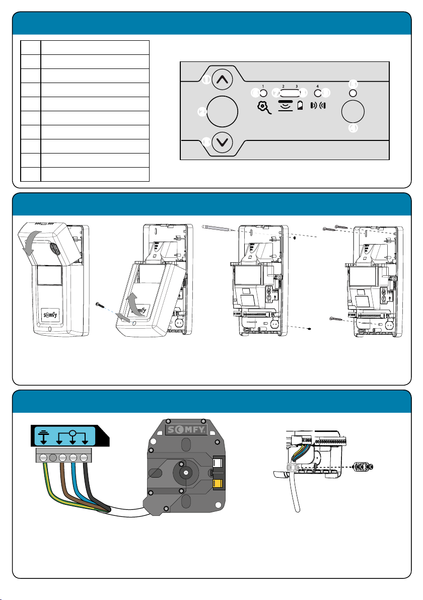
Rollixo RTS control panel
Remove the
courtesy light
cover.
No. Description
1Up button
2Stop button
3Down button
4Prog button
5Prog LED
6Motor & safety brake LED
7Safety edge LED
8Battery LED
9Photocell LED
3 421
Prog
STOP
L1 L2N
M
1 2 3 4
Bleu
Marron
Noir
Green/Yellow
Brown
Blue
Black
L1 L2N
M
1 2 3 4
Bleu
Marron
Noir
Sec
Safety EdgeStop
K
5 6 7 8 9 1
Green/Yellow
Brown
Blue
Black
Sec
Safety EdgeStop
K
5 6 7 8 9 1
Mounting the Rollixo RTS
Unscrew
and remove the
panel cover.
Mark the
wall drilling
positions.
Secure the
Rollixo RTS in
place.
Somfy motor wiring
Connect the motor wires into terminals 1, 2, 3
& 4 as illustrated above.
Note: The motor direction can be reversed during the
commissioning procedure.
Secure the motor supply
cable in place with the cable
clamp.
.
.
.
.
.
....

Page 5
L1 L2N
M
1 2 3 4
Bleu
Marron
Noir
Sec
Safety EdgeStop
K
5 6 7 8 9 1
Green/Yellow
Brown
Blue
Black
Sec
Safety EdgeStop
K
5 6 7 8 9 1
L1 L2N
M
1 2 3 4
Bleu
Marron
Noir
Sec
Safety EdgeStop
K
5 6 7 8 9 1
Green/Yellow
Brown
Blue
Black
Sec
Safety EdgeStop
K
5 6 7 8 9 1
Safety brake wiring
Connect the safety brake into
terminals 5 & 6.
Use the link provided to
connect terminals 5 & 6 if no
safety brake is required.
3 421
Prog
STOP
Unfold the aerial so
that it points vertically
downwards.
Powering up the Rollixo RTS
Screw the bulb
supplied into the
light fitting.
3 421
Prog
STOP
3 421
Prog
STOP
3 421
Prog
STOP
Refit the panel
cover and secure
with the screw.
Plug in the supply cable and
connect the the mains supply.
3 421
Prog
STOP
Refit the
courtesy light
cover.
3 42
1
Prog
STOP
3 4
2
1
Prog
STOP
If the motor LED comes on, check the
safety brake or link connection.
If the safety edge LED comes on, the safety
edge transmitter has not been recognised.
Prog
3 421
Prog
STOP
Prog
Prog
Prog
Prog
Prog
All the LED’s
come on briefly
and then go
out.
Prog
(This is normal if the safety edge transmitter
has not been paired to the Rollixo RTS yet).

Page 6
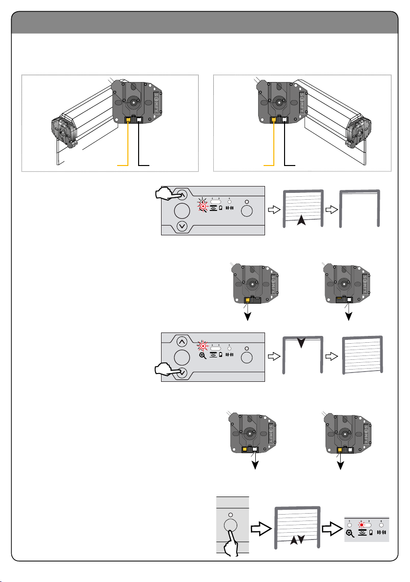
Motor direction of rotation setting
Press IN the motor limit buttons to allow
the motor to rotate during the direction and
limit setting procedure.
3 421
Prog
STOP
3 421
Prog
STOP
OR
3 421
Prog
STOP
3 421
Prog
STOP
on
3 421
Prog
STOP
3 421
Prog
STOP
3 421
Prog
STOP
3 421
Prog
STOP
motor on left side
yellow = up limit
motor on right side
white = up limit
3 421
Prog
STOP
3 421
Prog
STOP
3 421
Prog
STOP
OR
3 421
Prog
STOP
3 421
Prog
STOP
on
3 421
Prog
STOP
3 421
Prog
STOP
3 421
Prog
STOP
3 421
Prog
STOP
motor on left side
yellow = up limit
motor on right side
white = up limit
3 421
Prog
STOP
At the same time press and hold the UP & DOWN buttons on the control panel until the
door moves forward AND backwards, then release the buttons – the controller is now in
‘motor adjustment mode’, the motor LED light will flash slowly.
In motor adjustment mode, the Up & Down control buttons are in ‘hold to run’ mode -
you must press and hold the button in to operate the door up and down.
3 421
Prog
STOP
3 421
Prog
STOP
OR
3 421
Prog
STOP
3 421
Prog
STOP
on
3 421
Prog
STOP
3 421
Prog
STOP
3 421
Prog
STOP
3 421
Prog
STOP
motor on left side
yellow = up limit
motor on right side
white = up limit
3 421
Prog
STOP
solsol
3 421
Prog
STOP
20 mm
max
1 2 3 4
ON
3 screws
3 421
Prog
STOP
3 421
Prog
STOP
3 421
Prog
STOP
3 421
Prog
STOP
3 421
Prog
STOP
3 421
Prog
STOP
3 421
Prog
STOP
3 421
Prog
STOP
3 421
Prog
STOP
Prog
Press and hold the UP button to check the motor
direction
If the motor direction is correct, move on to page 7.
If the motor direction is incorrect, press and hold the
STOP button until the door jogs up and down > the
direction has been reversed > check again and move
on to page 7.
3 421
Prog
STOP
3 421
Prog
STOP
OR
3 421
Prog
STOP
3 421
Prog
STOP
on
3 421
Prog
STOP
3 421
Prog
STOP
3 421
Prog
STOP
3 421
Prog
STOP
motor on left side
yellow = up limit
motor on right side
white = up limit
3 421
Prog
STOP
Correct direction
of rotation
Incorrect direction
of rotation
3 421
Prog
STOP
3 421
Prog
STOP
OR
3 421
Prog
STOP
3 421
Prog
STOP
on
3 421
Prog
STOP
3 421
Prog
STOP
3 421
Prog
STOP
3 421
Prog
STOP
motor on left side
yellow = up limit
motor on right side
white = up limit
3 421
Prog
STOP
Prog
Prog
3 421
Prog
STOP
3 421
Prog
STOP
OR
3 421
Prog
STOP
3 421
Prog
STOP
on
3 421
Prog
STOP
3 421
Prog
STOP
3 421
Prog
STOP
3 421
Prog
STOP
motor on left side
yellow = up limit
motor on right side
white = up limit
3 421
Prog
STOP
3 421
Prog
STOP
3 421
Prog
STOP
OR
3 421
Prog
STOP
3 421
Prog
STOP
on
3 421
Prog
STOP
3 421
Prog
STOP
3 421
Prog
STOP
3 421
Prog
STOP
motor on left side
yellow = up limit
motor on right side
white = up limit
3 421
Prog
STOP
3 421
Prog
STOP
3 421
Prog
STOP
OR
3 421
Prog
STOP
3 421
Prog
STOP
on
3 421
Prog
STOP
3 421
Prog
STOP
3 421
Prog
STOP
3 421
Prog
STOP
motor on left side
yellow = up limit
motor on right side
white = up limit
3 421
Prog
STOP
3 421
Prog
STOP
3 421
Prog
STOP
OR
3 421
Prog
STOP
3 421
Prog
STOP
on
3 421
Prog
STOP
3 421
Prog
STOP
3 421
Prog
STOP
3 421
Prog
STOP
motor on left side
yellow = up limit
motor on right side
white = up limit
3 421
Prog
STOP
34
2
1
Prog
STOP
34
2
1
Prog
STOP
OR
34
2
1
Prog
STOP
34
2
1
Prog
STOP
on
34
2
1
Prog
STOP
34
2
1
Prog
STOP
34
2
1
Prog
STOP
34
2
1
Prog
STOP
motor on left side
yellow = up limit
motor on right side
white = up limit
34
2
1
Prog
STOP
Page 7
Motor limit setting
During the limit setting procedure, the Rollixo push button controls are in HOLD TO RUN mode.
Motor limit directions as shutter box projects towards you.
Press and hold the UP button
to move the door to the upper
limit position (use the UP &
DOWN buttons to fine tune the
door to the desired position).
3 421
Prog
STOP
3 421
Prog
STOP
OR
3 421
Prog
STOP
3 421
Prog
STOP
on
3 421
Prog
STOP
3 421
Prog
STOP
3 421
Prog
STOP
3 421
Prog
STOP
motor on left side
yellow = up limit
motor on right side
white = up limit
3 421
Prog
STOP
Press the motor Up end limit button IN to set
the ‘Open/Up’ limit position.
Left hand motor Right hand motor
OR
3 421
Prog
STOP
motor on left side
white = down limit
motor on right side
yellow = down limit
Left hand motor
installation
Right hand motor
installation
Yellow button
Open / Up
White button
Open / Up
White button
Close / Down
Yellow button
Close / Down
Press and hold the DOWN
button to move the door to the
lower limit position (use the UP
& DOWN buttons to fine tune the
door to the desired position).
Press the motor Lower end limit button to
set the Close / Down limit position.
Left hand motor Right hand motor
OR
3 421
Prog
STOP
motor on left side
white = down limit
motor on right side
yellow = down limit
OR
3 421
Prog
STOP
motor on left side
white = down limit
motor on right side
yellow = down limit
solsol
3 421
Prog
STOP
20 mm
max
1 2 3 4
ON
3 screws
3 421
Prog
STOP
3 421
Prog
STOP
3 421
Prog
STOP
3 421
Prog
STOP
3 421
Prog
STOP
3 421
Prog
STOP
3 421
Prog
STOP
3 421
Prog
STOP
3 421
Prog
STOP
Prog
Prog
3 421
Prog
STOP
3 421
Prog
STOP
OR
3 421
Prog
STOP
3 421
Prog
STOP
on
3 421
Prog
STOP
3 421
Prog
STOP
3 421
Prog
STOP
3 421
Prog
STOP
motor on left side
yellow = up limit
motor on right side
white = up limit
3 421
Prog
STOP
3 421
Prog
STOP
3 421
Prog
STOP
OR
3 421
Prog
STOP
3 421
Prog
STOP
on
3 421
Prog
STOP
3 421
Prog
STOP
3 421
Prog
STOP
3 421
Prog
STOP
motor on left side
yellow = up limit
motor on right side
white = up limit
3 421
Prog
STOP
3 421
Prog
STOP
3 421
Prog
STOP
OR
3 421
Prog
STOP
3 421
Prog
STOP
on
3 421
Prog
STOP
3 421
Prog
STOP
3 421
Prog
STOP
3 421
Prog
STOP
motor on left side
yellow = up limit
motor on right side
white = up limit
3 421
Prog
STOP
3 421
Prog
STOP
3 421
Prog
STOP
OR
3 421
Prog
STOP
3 421
Prog
STOP
on
3 421
Prog
STOP
3 421
Prog
STOP
3 421
Prog
STOP
3 421
Prog
STOP
motor on left side
yellow = up limit
motor on right side
white = up limit
3 421
Prog
STOP
Prog
Briefly press the PROG button until the door jogs to compete the motor set up procedure.
The motor & safety brake LED goes
out and the safety edge LED comes on.
Page 8
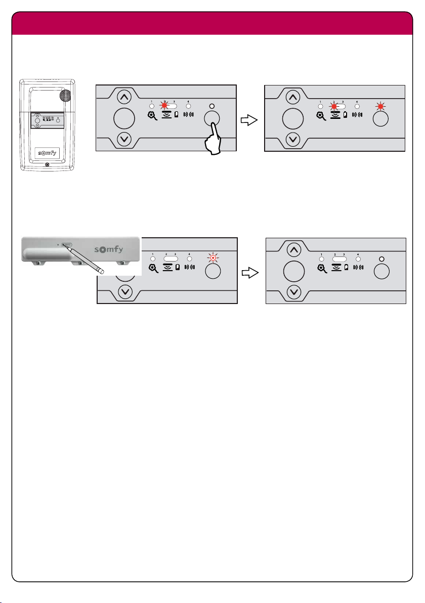
Pairing the safety edge transmitter
Bring the door and the bottom rail to a workable eye level. Press and hold the ‘Prog’ button
on the Rollixo panel until the LED light above it comes on – Then let go!
Now approach the Transmitter on the Bottom Rail – Using a small tool press the ‘Prog’
button on the unit until the Rollixo panel ‘Prog’ LED flashes, then let go (this could be up to 5
seconds) the 2 units are now active.
solsol
3 421
Prog
STOP
20 mm
max
1 2 3 4
ON
3 screws
3 421
Prog
STOP
3 421
Prog
STOP
3 421
Prog
STOP
3 421
Prog
STOP
3 421
Prog
STOP
3 421
Prog
STOP
3 421
Prog
STOP
3 421
Prog
STOP
3 421
Prog
STOP
solsol
3 421
Prog
STOP
20 mm
max
1 2 3 4
ON
3 screws
3 421
Prog
STOP
3 421
Prog
STOP
3 421
Prog
STOP
3 421
Prog
STOP
3 421
Prog
STOP
3 421
Prog
STOP
3 421
Prog
STOP
3 421
Prog
STOP
3 421
Prog
STOP
solsol
3 421
Prog
STOP
20 mm
max
1 2 3 4
ON
3 screws
3 421
Prog
STOP
3 421
Prog
STOP
3 421
Prog
STOP
3 421
Prog
STOP
3 421
Prog
STOP
3 421
Prog
STOP
3 421
Prog
STOP
3 421
Prog
STOP
3 421
Prog
STOP
Check the operation of the door by pressing the Rollixo Up & Down control buttons.
Check that the safety edge works by activating the edge.

Page 9
Positioning of Magnets
Bring the door down to its final closed/end limit position. If the door lands on floor and
stops, go to point
If the door comes to floor and retracts (bounces back) then see check the detail below, this
happens because the doors safety edge system has been activated;
Q. Are the end blocks sat in a final position that is lower than the floor level?
A. Raise the blocks and build up with packing.
Q. Is there a high point or bump in the floor?
A. Floor needs to be levelled.
Once you are happy that the door has been installed within its operating parameters then
we can fit the bottom magnet.
Mark the guide rail at its lowest point to match the arrow indicated on the right of the
Transmitter, the magnet arrows should now be aligned and no more than 10mm apart.
Now move the door up out of the way and use the temporary sticky pad to locate the magnet,
now permanently and mechanically fix the magnet with screws provided in place.
Locking out the Panel
3 421
Prog
STOP
3 421
Prog
STOP
Press buttons
Prog
STOP
and Prog
STOP
on the receiver until all the indicator lights flash.
Entry into programming mode by pressing button Prog
STOP
on the receiver is locked.
Entry into motor end limit setting mode via pressing buttons and on the receiver is
locked.
The parameter setting of the operating modes is locked.

Page 10
Deleting all remote controls from the memory
Press the ‘Prog’ button on the Rollixo RTS front panel for approximately 7 seconds until the
LED goes out:
solsol
3 421
Prog
STOP
20 mm
max
1 2 3 4
ON
3 screws
3 421
Prog
STOP
3 421
Prog
STOP
3 421
Prog
STOP
3 421
Prog
STOP
3 421
Prog
STOP
3 421
Prog
STOP
3 421
Prog
STOP
3 421
Prog
STOP
3 421
Prog
STOP
3 421
Prog
STOP
Prog
solsol
3 421
Prog
STOP
20 mm
max
1 2 3 4
ON
3 screws
3 421
Prog
STOP
3 421
Prog
STOP
3 421
Prog
STOP
3 421
Prog
STOP
3 421
Prog
STOP
3 421
Prog
STOP
3 421
Prog
STOP
3 421
Prog
STOP
3 421
Prog
STOP
Approximately 7 seconds
The LED will then begin to flash slowly and then go out - all remote controls have been deleted.
solsol
3 421
Prog
STOP
20 mm
max
1 2 3 4
ON
3 screws
3 421
Prog
STOP
3 421
Prog
STOP
3 421
Prog
STOP
3 421
Prog
STOP
3 421
Prog
STOP
3 421
Prog
STOP
3 421
Prog
STOP
3 421
Prog
STOP
3 421
Prog
STOP
Deleting the safety edge transmitter
Press the ‘Prog’ button on the Rollixo RTS front panel for approximately 14 seconds:
The LED will: come on - go out - start to flash rapidly - then let go of the ‘Prog’ button.
The LED will flash slower then go out.
The safety edge transmitter has been deleted.
solsol
3 421
Prog
STOP
20 mm
max
1 2 3 4
ON
3 screws
3 421
Prog
STOP
3 421
Prog
STOP
3 421
Prog
STOP
3 421
Prog
STOP
3 421
Prog
STOP
3 421
Prog
STOP
3 421
Prog
STOP
3 421
Prog
STOP
3 421
Prog
STOP
solsol
3 421
Prog
STOP
20 mm
max
1 2 3 4
ON
3 screws
3 421
Prog
STOP
3 421
Prog
STOP
3 421
Prog
STOP
3 421
Prog
STOP
3 421
Prog
STOP
3 421
Prog
STOP
3 421
Prog
STOP
3 421
Prog
STOP
3 421
Prog
STOP
solsol
3 421
Prog
STOP
20 mm
max
1 2 3 4
ON
3 screws
3 421
Prog
STOP
3 421
Prog
STOP
3 421
Prog
STOP
3 421
Prog
STOP
3 421
Prog
STOP
3 421
Prog
STOP
3 421
Prog
STOP
3 421
Prog
STOP
3 421
Prog
STOP
solsol
3 421
Prog
STOP
20 mm
max
1 2 3 4
ON
3 screws
3 421
Prog
STOP
3 421
Prog
STOP
3 421
Prog
STOP
3 421
Prog
STOP
3 421
Prog
STOP
3 421
Prog
STOP
3 421
Prog
STOP
3 421
Prog
STOP
3 421
Prog
STOP
Approximately 14 seconds
solsol
3 421
Prog
STOP
20 mm
max
1 2 3 4
ON
3 screws
3 421
Prog
STOP
3 421
Prog
STOP
3 421
Prog
STOP
3 421
Prog
STOP
3 421
Prog
STOP
3 421
Prog
STOP
3 421
Prog
STOP
3 421
Prog
STOP
3 421
Prog
STOP
solsol
3 421
Prog
STOP
20 mm
max
1 2 3 4
ON
3 screws
3 421
Prog
STOP
3 421
Prog
STOP
3 421
Prog
STOP
3 421
Prog
STOP
3 421
Prog
STOP
3 421
Prog
STOP
3 421
Prog
STOP
3 421
Prog
STOP
3 421
Prog
STOP
solsol
3 421
Prog
STOP
20 mm
max
1 2 3 4
ON
3 screws
3 421
Prog
STOP
3 421
Prog
STOP
3 421
Prog
STOP
3 421
Prog
STOP
3 421
Prog
STOP
3 421
Prog
STOP
3 421
Prog
STOP
3 421
Prog
STOP
3 421
Prog
STOP
Prog
solsol
3 421
Prog
STOP
20 mm
max
1 2 3 4
ON
3 screws
3 421
Prog
STOP
3 421
Prog
STOP
3 421
Prog
STOP
3 421
Prog
STOP
3 421
Prog
STOP
3 421
Prog
STOP
3 421
Prog
STOP
3 421
Prog
STOP
3 421
Prog
STOP
solsol
3 421
Prog
STOP
20 mm
max
1 2 3 4
ON
3 screws
3 421
Prog
STOP
3 421
Prog
STOP
3 421
Prog
STOP
3 421
Prog
STOP
3 421
Prog
STOP
3 421
Prog
STOP
3 421
Prog
STOP
3 421
Prog
STOP
3 421
Prog
STOP
solsol
3 421
Prog
STOP
20 mm
max
1 2 3 4
ON
3 screws
3 421
Prog
STOP
3 421
Prog
STOP
3 421
Prog
STOP
3 421
Prog
STOP
3 421
Prog
STOP
3 421
Prog
STOP
3 421
Prog
STOP
3 421
Prog
STOP
3 421
Prog
STOP
Prog
solsol
3 421
Prog
STOP
20 mm
max
1 2 3 4
ON
3 screws
3 421
Prog
STOP
3 421
Prog
STOP
3 421
Prog
STOP
3 421
Prog
STOP
3 421
Prog
STOP
3 421
Prog
STOP
3 421
Prog
STOP
3 421
Prog
STOP
3 421
Prog
STOP
Prog
solsol
3 421
Prog
STOP
20 mm
max
1 2 3 4
ON
3 screws
3 421
Prog
STOP
3 421
Prog
STOP
3 421
Prog
STOP
3 421
Prog
STOP
3 421
Prog
STOP
3 421
Prog
STOP
3 421
Prog
STOP
3 421
Prog
STOP
3 421
Prog
STOP
solsol
3 421
Prog
STOP
20 mm
max
1 2 3 4
ON
3 screws
3 421
Prog
STOP
3 421
Prog
STOP
3 421
Prog
STOP
3 421
Prog
STOP
3 421
Prog
STOP
3 421
Prog
STOP
3 421
Prog
STOP
3 421
Prog
STOP
3 421
Prog
STOP
Return to the factory mode
After deleting all the remote controls and safety edge transmitters from the memory:
Press simultaneously the Up & Down buttons on the front panel.
The door will jog Up & Down
and the motor LED will start
flashing slowly.
solsol
3 421
Prog
STOP
20 mm
max
1 2 3 4
ON
3 screws
3 421
Prog
STOP
3 421
Prog
STOP
3 421
Prog
STOP
3 421
Prog
STOP
3 421
Prog
STOP
3 421
Prog
STOP
3 421
Prog
STOP
3 421
Prog
STOP
3 421
Prog
STOP
Prog
The Rollixo RTS control panel has now been set back to the factory mode.
3 421
Prog
STOP
3 421
Prog
STOP
OR
3 421
Prog
STOP
3 421
Prog
STOP
on
3 421
Prog
STOP
3 421
Prog
STOP
3 421
Prog
STOP
3 421
Prog
STOP
motor on left side
yellow = up limit
motor on right side
white = up limit
3 421
Prog
STOP

Page 11
Is the floor level?
Up & Bottom limits set?
Safety edge Transmitter waking up when tapped?
Up, Stop & Down working correctly with Courtesy light?
Does safety edge activate when it hits an obstruction?
When closed is the rubber edge uniform and not deformed?
Have magnets been fitted where necessary?
Is the Alarm active?
Do all the accessories and Key fobs work correctly?
Have you locked out the panel?
End User Demonstration?
Complete Check List
Page 12
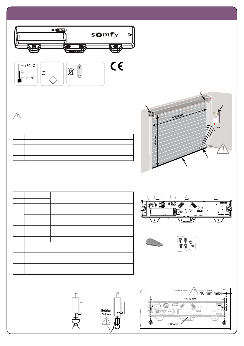
XSE transmitter - Installation instructions
IP 44
3,6V Lithium AA
Ref.1782078
433.42 MHz
5118797A
SOMFY declares that this product complies with
the essential requirements of applicable European
directives. A Declaration of Conformity is available
at www.somfy.com/ce (ROLLIXO).
General view of the installation
Installing the XSE transmitter inside the garage on the final slat on
the right-hand side
aFall protection
bMotor
cReceiver
dXSE transmitter
eOptical safety edge (OSE) or resistive safety edge (ESE)
b
c
e
d
a
Product description
The XSE transmitter is designed to be installed with an optical safety edge (OSE) or a resistive safety edge (ESE), a receiver and an RDO
CSI motor approved by Somfy.
1MODE button Safety edge test / shipping mode
2LED1
3Dipswitch 1 Adjusting the transmitter operating time
Dipswitch 2
Dipswitch 3 Adjusting the sensitivity of the movement sensor
Dipswitch 4 Activating the upper magnet
4LED2 Commissioning (waking up/programming) the
transmitter
5PROG button Programming the transmitter
6Optical safety edge (OSE) connectors
7Resistive safety edge (ESE) connector
83.6V Lithium AA battery
9Optical safety edge (OSE) connection tool
10 4 fixing screws for the XSE transmitter + 2 screws for fixing the
XSE transmitter to the final slat
123456
7
8
910
Routing the cables and fixing the XSE transmitter to the final slat
> In the final slat
Ø 3,3 mm Ø 3,3 mm
ESE OSE

Page 13
XSE transmitter - Installation instructions
> In the rubber
Ø 3,3 mm Ø 3,3 mm
OSE
R R
Installing the battery and running the automatic test
0 s ... 120 s
5 s
5 s
LED2LED1
LED2LED1
LED2LED1
LED2LED1
3,6V Lithium A
A
Or Or Or Or
G G
Wiring the safety edge on the transmitter
> Optical safety edge (OSE)
Do not strip the wires. Leave excess wire on each connector (min. 5 mm). Leave excess cable in case of a new installation.
If recutting cables, use a suitable tool to remove the sheath without damaging the wires.
Press down on the optical cell wires using the connection tool until you hear a CLICK.
> 1k2 or 8k2 resistive safety edge (ESE)
CLAC !
5 mm mini
TX RX

Page 14
XSE transmitter - Installation instructions
X 4
G G Or Or R R
Green Green
flashing Orange Orange
flashing Red Red
flashing
10 mm maxi.
3 421
Prog
STOP
3 421
Prog
STOP
3 421
Prog
STOP
3 421
Prog
STOP
3 421
Prog
STOP
4s
2s
Commissioning and testing the safety edge
The rubber crushing test is compulsory for resistive
safety edges (ESE).
Closing the XSE transmitter
Remove appropreate tabs as required
Installing a base magnet
> Compulsory for resistive safety edges (ESE)
> Recommended for optical safety edges (OSE)
• Installing a base magnet:
• extends the battery life
• eliminates the risk of ground detection,
secures the closing of the door
• automatically activates the maximum level of
sensitivity of the movement sensor
• increases the sensor operating time from 25 to
35 seconds when the base magnet is detected.
Programming the XSE transmitter in to the Rollixo receiver
8 s
LED1
LED1
LED1 LED1 LED1 LED2
LED2
LED2
LED2
SW2
LED1
MODE
3s
RR G G
R

Page 15
XSE transmitter - Installation instructions
Recycling
Never dispose of used batteries with household waste. They must be taken to the relevant recycling points.
50 mm mini.
70 mm maxi.
10 mm maxi.
Dipswitch 4 = ON
Configuring the XSE transmitter operating time
Operating time Dipswitch 1 Dipswitch 2
25 secs (35 secs if base magnet installed) OFF OFF
35 secs ON OFF
60 s OFF ON
Repairs
> Problem on XSE transmitter LED1 and LED2:
/ /
Stage 1: CHECK THE BATTERY
Remove the battery then press a button (PROG or MODE) to
discharge the residual energy from the electronics. Refit the
battery and wait for the automatic battery test to be completed
(an orange light flashes to signal the test is under way - it may
last up to 2 minutes) (Fig. 4).
• If LED1 and LED2 light up red for 5 seconds, replace the
battery and repeat the operations above.
• If LED1 and LED2 light up green for 5 seconds, skip to
step 2.
Stage 2: CHECK THE OPERATION OF THE SAFETY EDGE
Launch safety edge detection and test the safety edge (Fig. 6)
• If LED2 lights up green then the safety edge and
transmitter are operating correctly. Squeeze the safety
edge and check that LED2 lights up red.
• If not, go to step 3.
Stage 3: DETERMINE THE ORIGIN OF THE FAULT: XSE
TRANSMITTER OR SAFETY EDGE?
Disconnect the safety edge.
Test 1: launch safety edge detection (Fig. 6)
• If LED2 flashes red for 8 seconds then the XSE transmitter is
operating correctly.
• If not, the XSE transmitter maybe faulty.
Test 2: (optional): launch safety edge detection (Fig. 6) by
short-circuiting the 2 contacts on the ESE J3 connector (using a
flat-blade screwdriver).
• If LED2 lights up red for 8 seconds then the XSE transmitter
is operating correctly.
• If not, the XSE transmitter maybe is faulty.
If tests 1 and 2 show that the transmitter is
operating correctly, replace the safety edge.
> Ground detection problem (no door deformation
Check that there is a magnet fitted as shown in Fig. 8 and
install one if necessary or rectify the ground to make it level
and uniform.
> Problem waking up the transmitter from fully open
position
Important: For each test, wait until LED2 goes off to test that
the transmitter wakes up.
Test 1: Check that the XSE transmitter is working by tapping it
and check that LED2 lights up green. If not, press and hold the
PROG button for 3 seconds and retest. If the problem persists,
replace the XSE transmitter.
Test 2: Open the door fully, check that a bottom magnet is
fitted and/or that dipswitch 3 is ON, then retest.
Test 3: If the problem persists, install an upper magnet
(Fig. 10 a) and set dipswitch 4 to ON then retest.
If the problem persists, replace the XSE
transmitter.
11
12

www.rollixo.co.uk
Somfy Ltd
Moorfield Road
Yeadon
Leeds
West Yorkshire
LS19 7BN
T. 0113 391 3030
F. 0113 391 3010
E. sales.uk@somfy.com
© SOMFY 201113
Other manuals for Rollixo RTS
5
Table of contents
Other SOMFY Indoor Furnishing manuals

SOMFY
SOMFY sonesse 30 rts User manual

SOMFY
SOMFY Solar Pack User manual

SOMFY
SOMFY Oximo io User manual

SOMFY
SOMFY Roll Up 28 RTS User manual

SOMFY
SOMFY Junior RU 30 RTS User manual

SOMFY
SOMFY 152134 User manual

SOMFY
SOMFY sonesse 40 User manual

SOMFY
SOMFY Oximo 40 WireFree RTS User manual

SOMFY
SOMFY sonesse 30 rts User manual
Popular Indoor Furnishing manuals by other brands

Regency
Regency LWMS3015 Assembly instructions

Furniture of America
Furniture of America CM7751C Assembly instructions

Safavieh Furniture
Safavieh Furniture Estella CNS5731 manual

PLACES OF STYLE
PLACES OF STYLE Ovalfuss Assembly instruction

Trasman
Trasman 1138 Bo1 Assembly manual

Costway
Costway JV10856 manual


