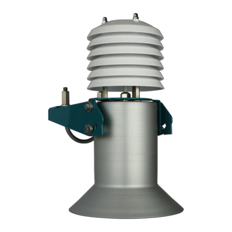
SOMMER USH-9 User manual

USH-9
Ultrasonic level sensor
User Manual
Setup version 2.43
2019-03-28
Sommer GmbH
All rights reserved.

The Copyrights for this manual are exclusively owned by
Sommer GmbH
A-6842 Koblach
This manualor parts ofitmay only be copied or passedon tothird parties with written permission of Sommer GmbH. This applies to
printed as well as digital issues of this manual.
Sommer GmbH
Strassenhaeuser 27
6842 Koblach
Austria
http://www.sommer.at
Email: office@sommer.at
Tel.: +43 5523 / 55 989 - 0
Fax: +43 5523 / 55 989 - 19
Validity
This manual applies to the ultrasonic level sensor USH-9and is valid for the setup version 2.43 with all its
subversions.
The firmware version can be viewed with the function Device status and is listed in the boot message.
Created:
Last update:
Approved:
File:
jofri 2018-07-09
jofri 2019-03-28
wosom 2018-09-12
manual_USH-9_en.docx

CE compliance
This product is in conformity with the following directives and standards:
EMV Directive 89/336/EEC EWG EN 61326
RoHS II Directive 2011/65/EU
RoHS III Delegated Directive (EU) 2015/863

Safety information
Please read this manual carefully before installing or operating this equipment. Non-compliancewith the
instructions given in this manualcan result infailureor damage of the equipmentormay endanger people
by injuries through electrical or mechanic impact.
-Installation and electrical connections must be carried out by qualified personnel familiar with the
applicable regulations and standards.
-Installation of equipment on towers or poles poses the risk of falling, slipping or dropping of objects.
Contact your safety officer or consult applicable safety regulations for precautions and proper per-
sonal safety equipment.
-Do not perform any installations in bad weather conditions, e.g. thunderstorms.
-Prior to installation of equipment informthe owner of the measurementsiteor the authority respon-
sible for it. Upon completion, secure the installation from trespassers.
-Maintenance and repair must be performed by trained personnel or an engineer of Sommer GmbH.
Only replacement parts supplied by Sommer GmbH should be used for repairs.
-Make sure that NO power is connected to the equipment during installation and wiring.
-Only use a power supply that complies with the power rating specified for this equipment.
-Keep equipment dry during wiring and maintenance.
-If applicable, it is recommended to use accessories of Sommer GmbH with this equipment.
Disposal
After the equipment has reached the end of its lifetime disposeof the items at your next waste recycling
facility. DO NOT dispose of the equipment to residual waste.

Content
1Introduction................................................................................................................................. 6
2Unpacking.................................................................................................................................... 7
3Quick start ................................................................................................................................... 8
3.1 Installation............................................................................................................................ 8
3.2 Connection of the USH-9 to a computer.................................................................................. 8
3.3 Sensor configuration.............................................................................................................. 8
4Specifications............................................................................................................................... 9
5Principles of operation.................................................................................................................10
6Installation..................................................................................................................................11
6.1 Selection of the measurement site ........................................................................................11
6.2 Mounting.............................................................................................................................11
6.2.1 Power supply..............................................................................................................12
6.2.2 Signal cables...............................................................................................................13
6.2.3 Lightning protection....................................................................................................13
6.3 Maintenance........................................................................................................................13
7Operation....................................................................................................................................14
7.1 How to setup the USH-9 for snow applications.......................................................................14
7.2 How to setup the USH-9 for water level measurements..........................................................14
7.3 How to test the USH-9..........................................................................................................14
8Communication...........................................................................................................................15
8.1 Connector pin configuration..................................................................................................15
8.2 Communication with a PC.....................................................................................................15
8.3 Connection to a data logger..................................................................................................17
8.3.1 RS-485........................................................................................................................17
8.3.2 SDI-12 ........................................................................................................................17
8.3.3 Analog output.............................................................................................................18
8.4 Modbus communication.......................................................................................................18
9Configuration..............................................................................................................................19
9.1 Setup using Commander.......................................................................................................19
9.2 Setup using a terminal program.............................................................................................19
9.3 General settings ...................................................................................................................20
9.4 Level/Distance measurement................................................................................................20
9.5 Serial data output.................................................................................................................21
9.6 RS-485 interface...................................................................................................................23
9.6.1 System key and device number....................................................................................23
9.6.2 Output time (D-I-D).....................................................................................................23
9.6.3 Operation modes........................................................................................................24
9.6.4 Waking-up of a connected datalogger .........................................................................24
9.6.5 Output protocols.........................................................................................................24
9.6.6 Commands .................................................................................................................27
9.7 SDI-12 interface....................................................................................................................28
9.7.1 SDI-12 address (D-C)....................................................................................................28
9.7.2 Measurement commands............................................................................................28

9.7.3 Sensor configuration commands..................................................................................29
9.8 Modbus communication.......................................................................................................29
9.9 Analog output ......................................................................................................................30
10 Parameter definition ...................................................................................................................32
Appendix A Measurement values.....................................................................................................47
A.1 Error and exception values....................................................................................................47
Appendix B RS-485 interface ............................................................................................................48
B.1 Protocols..............................................................................................................................48
B.1.1 “Sommer” protocol.....................................................................................................48
B.1.2 Standard protocol.......................................................................................................49
B.2 Commands and answers .......................................................................................................49
B.3 Error codes...........................................................................................................................51
B.4 Sommer CRC-16 ...................................................................................................................51
Appendix C SDI-12 interface.............................................................................................................52
C.1 Standard SDI-12 commands ..................................................................................................52
C.1.1 Sensor identification ...................................................................................................52
C.1.2 Triggering a measurement...........................................................................................52
C.1.3 Requesting measurement values .................................................................................52
C.1.4 Requesting continuous measurements.........................................................................53
C.2 Extended SDI-12 commands..................................................................................................53
C.2.1 Reading and writing sensor configurations ...................................................................53
C.2.2 Adoption of settings....................................................................................................54
Appendix D Modbus ........................................................................................................................55
D.1 Modbus default settings .......................................................................................................55
D.2 Modbus Configuration..........................................................................................................55

6
1Introduction
Continuous water-level and snow depth measurements are very important in water resource manage-
ment and avalanche risk forecast.
The USH-9 is a continuous measurement device for the contact-free determination of water level and
snow depth. It measures the transit time of an ultrasonic signal between a variable surface and the
USH-9 sensor, and translates it to a level or distance. An integrated processor compensates the de-
tected signal for temperature and filters interfering reflections of precipitation within the measure-
ment path.
The USH-9 sensor contains an additional feature to sense precipitation and thus offers the option to
detect the settling of snow. Therefore, the sensor may also be implemented in observation systems
that monitor road conditions.

7
2Unpacking
When unpacking your USH-9 sensor box please make sure that the following items are present:
-USH-9 sensor
-Mounting bracket for Ø32…60 mm tubing
-MAIN sensor cable
-Manual on USB stick
In case of missing or damaged items please contact your Sommer sales partner.
The following items are available as options:
-Commander software
-Shielded, UV-resistant data cable, 6 m long, with water resistant 8-pole-connector
-USB to RS485 converter cable

8
3Quick start
This section will guide you through the most important steps to set up a fully operating level monitor-
ing system with an USH-9. It is divided into three main parts: installation, connection to a PC and sensor
configuration.
3.1 Installation
1. Select a proper and representative measurement site (Section 6.1)
2. Mount the USH-9 on a suitable mast (Section 6.2)
3.2 Connection of the USH-9 to a computer
1. Install the Commander software
2. Connect the USH-9 to your computer using the supplied USB to RS485 converter cable (Section
8.2)
3. Connect a 9…28 VDC power supply to the USH-9
4. Start the Commander software and establish a connection to the USH-9 (Section 8.2)
3.3 Sensor configuration
1. Select language, decimal character, units and decimal places (Section 9.3)
2. Select the measurement trigger (Section 9.3)
3. Configure and calibrate the snow depth measurement (Section 9.4)
4. Option: Configure analog outputs (Section 9.9)
5. Define the scope and structure of the data output (Section 9.5)
Upon successful configuration the USH-9may be connected to adata logger for continuous monitoring
(Section 8.3).

9
4Specifications
Physical and environmental
Powersupply
9…27 V; Reverse voltage protection, overvoltage protection
Power consumption at 12 VDC
Sleep mode: <0.4 mA
Active measurement: typically 40mA (max. 300 mA for 0.05 s)
Shield heating (optional): 1 A
Outputs
RS-485 ASCII / Modbus RTU
SDI-12
2 Analog outputs 4…20 mA (14 bit, max. load 250 Ω)
Operating temperature
-40…60 °C (-40…140 °F)
Storage temperature
-40…60 °C (-40…140 °F)
Environmental humidity
0…100 %rH
Protection rating
IP 64
Lightningprotection
Integrated protection against indirect lightning with a discharge
capacity of 0.6 kV peak
Housing material
Anodized aluminium
Mounting bracket
Ø32…60 mm
Size Ø x H
Ø180 x 320 mm
Weight
1.2 kg
Snow depth measurement
Measurement range
0.7…10 m
Nearblanking distance
0.7 m
Accuracy
max. ± 1cm; typically 0.1% FS
Resolution
1 mm
Non-linearity
≤0.15%
Measurement duration
2…20 s
Measurement interval
20 s…3 h
Measurement principle
Ultrasonic(frequency 50 kHz)
Beam aperture
12°
Temperature measurement
Temperature sensor
Pt1000 with radiation shield
Measurement range
-40…60 °C (-40…140 °F)
Accuracy
0.3 °C
Resolution
0.01 °C
Table 1: Specifications

10
5Principles of operation
The USH-9 is a sensorto measure distance contact-free. Ultrasonicpulses with afrequencyof 50 kHz
are emitted from the sensor-head and are reflected at any surface. The reflected signal is then de-
tected by the sensorand from thetravelling-timeof the pulsesthedistanceto the surfaceis calculated.
Figure 1 illustrates the path of the ultrasonic signal.
The ultrasonic pulses received by the sensor head are filtered for interferences and disturbing reflec-
tions, e.g. from precipitation. This permits reliableand accurate level measurements even during rain
or snowfall, or when the snow is of very low density.
As the speed of sound is temperaturedependent, the USH-9is equipped withan integrated Pt1000air
temperature sensor to automatically correct the measured distance and snow depth.
With the integrated, intelligent signal processing and the automaticswitching between standby- and
measurement-mode the power consumption can be minimized. With a 12-Ah battery the USH-9 can
be operated for approx. 24 days with one measurement per minute.
Figure 1: Ultrasonic signal of the USH-9 sensor

11
6Installation
6.1 Selection of the measurement site
The selection of a suitable site is crucial to gain accurate water levels and snow depth data that are
representative of the monitored area. Several aspects have to be considered when choosing a site,
especially for snow depth measurements:
1. The measurement spot should be representative of the monitored area. This applies to the
weather conditions as well as the ground surface. Different surfaces, e.g. grass and gravel, have
different thermal properties and consequently influence snow accumulation and snow melt.
2. The terrain should be flat or only be slightly sloping. There should be no troughs or hills.
3. There should be no boulders, trees, fencesor other objects on and around the measurement spot.
Any obstacle can cause snow drift and thus affect the snow depth measurement.
4. The site should be exposed to wind as little as possible.
5. The site must be safe from avalanches.
6. If the measurement spot is on or near a slope any snow gliding has to be ruled out.
6.2 Mounting
The USH-9 can be mounted toahorizontaltube withthe includedbracket (max. tube diameter60 mm)
shown in Figure 2.
Figure 2: USH-9 with mounting bracket

12
When planning the installation of aUSH-9 the extension of the cone-shaped measurement beamhas
to be taken into account. The higher the sensor is mounted the bigger the diameter of the measure-
ment spot. Consequently, the mast and cross-beam must be designed in such a way that they do not
interfere with the ultrasonic beam and thus create unwanted reflections. The same applies to river
banks and channel walls in water level applications. Consult the table in Figure 3 for recommended
distances between mast and measurement spot.
Figure 3: Measurement spot and USH-9 position
It is recommended to mount the USH-9 one meterabove the maximum expected level and minimum
3 m above ground. The maximum mounting height is 10.5 m above ground. As an accessory, Sommer
provides a 1.6 m long, rotatable cross-arm for easy sensor mounting.
For accurate measurements the USH-9 should be mounted within ±6° perpendicular to the snow/
ground surface.
!
Attention
If the measurement spot is sloping, make sure the USH-9 ismounted perpen-
dicularto the snow/ground surface! Also, do not install the USH-9on a hori-
zontal podium in the slope!
Nevertilt the USH-9 towards the base of the mast as this can cause unwanted
reflections. To avoid such a situation, consider rotating the mast or selecting
another measurement spot.
If a snow-depth monitoring site needs tobe secured by a fence, the distance between the fence and
the USH-9 should be large enough to avoid snow build-up or snow drift.
6.2.1 Power supply
The USH-9 is designed for extreme environmentalconditions at remote sitesand with no grid connec-
tion. The sensor switches automatically into standby-mode between measurements and thus con-
sumes only approx. 0.2 Ah per day (measurement duration 6 sec and measurement interval 60 sec)
which can be supplied by a 12V-solar-generator mounted to the mast.
H [m]
Ø [m]
DB
2
0.6
1.0
3
1.0
1.2
4
1.3
1.4
5
1.6
1.6
6
1.9
1.8
7
2.2
2.0
8
2.5
2.2

13
6.2.2 Signal cables
Please consider the maximum cable lengths for the applied transmission protocol:
Protocol
Max. cable lenth [m]
SDI-12
60
RS-485
300
Table 2: Maximum cable lengths
Cable lengths longer than 60 m require a heavier gage wire if the power supply drops below 11 V.
6.2.3 Lightning protection
If the underground at the measurement sitepermits sufficient current dissipationit is strongly recom-
mended to equip the sensor support ormast with properly dimensioned lightningprotection. Consult
an expert for advice.
The USH-9 is protected against overvoltage. If a data logger is mounted to the mast, its ground lug
must be properly connected to earth ground.
6.3 Maintenance
The USH-9 generally does not require any special maintenance. However, the device should be in-
spected occasionally for damage and a dirty sensor surface. To remove dirtuse a wet cloth with little
force. Do not use any abrasive detergent or scraping tool!

14
7Operation
7.1 How to setup the USH-9 for snow applications
By default the USH-9 is configured for snow applications. This can be checkedin the setting Snow ap-
plication, which is turned.
If the USH-9 needs to be re-configured for snow applications, set
1. Snow application to on,
2. Rate of change, filter (RoC) to on,
3. Rate of change, maximum (./h) to the default value of 20 mm/h,
4. Moving filter, duration to 180 seconds, and
5. Moving filter, type to elim. all spikes.
Settings 2 to 4 may be adapted to values better suited for your application.
!
Attention
Make sure to upload the modified parametersto the USH-9 andtest the new
settings as described in Section 7.3!
7.2 How to setup the USH-9 for water level measurements
If the USH-9 is used for water level monitoring, set
1. Snow application to off,
2. Rate of change, filter (RoC) to off,
3. Moving filter, duration to 0seconds, and
4. Moving filter, type to median.
Settings 2 to 4 may be adapted to the flow conditions of your river or channel.
!
Attention
Make sure to upload the modified parameters to the USH-9 and test the new
settings as described in Section 7.3!
7.3 How to test the USH-9
To test the USH-9 and to verify its distance/level measurements turn the device upside down sothat
it is facing the ceiling of a room. Now, click the button Level/distance test in the Level and distance
menu. The USH-9 then triggers a measurement and returns the current distance and level.
Place a sturdy, flat object(e.g. book) underneath the USH-9and performadditional measurements to
check a second distance/level.
!
Attention
If the USH-9 is configured for snow applications do notuse the general meas-
urement function (Measurement (F3)-tab)of the Commander!The snow appli-
cation mode has a measurement filter (Rate of change, filter (RoC)) that sup-
presses abrupt level changes. Thus, it may take some time for the USH-9 to
read the actual distance.

15
8Communication
8.1 Connector pin configuration
Figure 4: Pin configuration of the connector MAIN
Pin
Colour1
Function
Description
Powersupply
1
white
GND
Ground
2
brown
Vsupply
9…27 VDC
Triggerinput
3
green
Trig
low: 0…0.6 V, high: 2…27 V
RS-485 interface
4
yellow
RS485 A2
1 x RS-485 (1200…115200 Baud)
5
grey
RS485 B2
SDI-12 interface
6
pink
SDI-12
1 x SDI-12 (1200 Baud)
Analog outputs
7
blue
IOUT2
Temperature (4…20 mA)
8
red
IOUT1
Snow depth (4…20 mA)
Table 3: Configuration of the connector MAIN
!
Attention
The analog outputs and the trigger input are referenced to GND on pin 1.
8.2 Communication with a PC
Communication between the USH-9 and a PC can be established via the sensors RS-485 interface and
the supplied USB to RS-485 converter. Perform the following steps to set up the communication be-
tween the USH-9 and your PC:
1
Wire colour of the provided “Sommer” cable
2
According to TI notation which differs from the standard EIA notation

16
5. Connectthe provided USB to RS-485 converterto the USH-9 MAIN cable and a USB port on your
PC as illustrated in Figure 5. Verifythat the newlycreated virtualCOM-port has the following com-
munication settings:
-Baud rate 9600
-Data bits 8
-Parity none
-Stop bits 1
-Flow control none
6. Connect a DC power supply to the USH-9 as shown in Figure 5.
7. If required, install the driver of the USB to RS-485 converter.
8. Install the Commander software on your PC.
9. Start the Commander software.
10. Click on Communication assistant on the right-hand side of the Commander window and follow
the instructions. During this procedure the communication assistant willsearch for connected de-
vices. Upon successful completion the new connection is added to the Connections list (tab Con-
nections (F8)).
11. In the Communication Sectionat the right-hand sideof the Commanderwindowselect Mode Con-
nection and the previously created connection from the drop-down list.
12. Click Connect to establish a connection with the USH-9. If the connection was successful a green
icon is displayed at the top-right corner of the Commander window.
13. Select the tab Paramters (F2) and click Download parameters from device. The complete parame-
ter list is transferred from the sensor to your PC and displayed in the Parameter window.
14. Select the tab Measurement (F3) and click Start polling measurements. Select Polling with meas-
urements and confirmthe Warning. Now, the device performs consecutive measurementsatthe
fastest possible rate. Click Stop polling to cancel data acquisition.
Figure 5: Wiring of the USH-9 with a PC

17
8.3 Connection to a data logger
8.3.1 RS-485
The USH-9 can be connected to a data logger via RS-485 according to Figure 6.
Figure 6: Wiring of the USH-9 with a data logger via RS-485
8.3.2 SDI-12
The USH-9 can be connected to a data logger via SDI-12 according to Figure 7. SDI-12 uses a shared
bus with a ground wire, a data wire (indicated as SDI-12) and an optional +12 V wire.
!
Attention
The connection with the 12 V power supply is optional and depends on the
connected SDI-12master device (typically a data logger).
Figure 7: Wiring of the USH-9 with a data logger via SDI-12

18
8.3.3 Analog output
The analog outputs of the USH-9 can be connected to a data logger according to Figure 8.
!
Attention
If a data loggeris connected tothe IOUT outputs the resistance of the logger
input(s) must not exceed 470 Ω.
Figure 8: Wiring of the analog outputs of the USH-9
8.4 Modbus communication
For Modbus communication the USH-9 is wired according to Table 4.
Modbus
ConnectorMAIN
Connection wire
Description
Common
Pin 1
White
GND
D1 - B/B
Pin 4
Yellow
RS-485 A
D0 - A/A
Pin 5
Grey
RS-485 B
Table 4: Connection to a Modbus
The USH-9 does not have termination resistors and does not need BUS polarization resistors. There-
fore, only a RS-485 BUS termination has to be implemented externally.

19
9Configuration
9.1 Setup using Commander
A simple and comfortable way to configure the USH-9 is the PC software Commander by Sommer.
After establishing aconnection as described in Section 8.2 the sensor settings can be accessed by se-
lecting the tab Paramters (F2) and clicking Downloadparameters from device. The completeparameter
list is transferredfrom the sensor to your PC and displayed in the Parameter window. Now, the settings
can be modified, saved in a parameter file on your PC and uploaded again to the USH-9. See Section
10 for a complete list of sensor settings.
!
Attention
During the first communication with anew sensorthe parameterschema of
the sensorhas to be transferred to the local PC. Only then the menu structure
is available in the Commander.
Besides the sensor configuration utility the Commander provides additional features:
-Spectrum-Mode to visualize ultrasonic spectra (used for diagnosticpurposes,e.g., multiple reflec-
tions)
-Terminal-Mode to check data transfer and to access the sensor settings menu directly.
Hint
A detailed description of the Commander can be found in the online help or in
the Commandermanual.
9.2 Setup using a terminal program
The Commander software ships with an integrated terminal program. However, communication with
the USH-9 can be performed with any terminal program.
Perform the following steps to access the setup menu of the USH-9 using a terminal program:
1. After establishing a connection with the USH-9as described in Section 8.2open the preferred ter-
minal program on your PC.
2. Select the COMport assigned to the USB/RS-485converter and adjust the communicationsettings
as described in Section 8.2.
3. After successful connection the setup menu can be accessed by entering three question marks
(???) in quick succession.
Hint
As an unwanted switching into the menu mode has to be avoided the timing of
the three question marks ??? is very restrictive and mustnever be finished
with Return/Enter. This is especially important for command line tools, which
may automatically send a closing "Carriage return”.
The menu items can be selected by entering the letter assigned to each item. Upon selection a sub-
menu is opened or the selected parameter is displayed with its unit. Changes to values are confirmed
with Return/Enter ordiscarded with Esc. Menus are closed with X. After closing the main menu with X
the sensor performs an initialization.
If the USH-9 is re-powered a boot messagecontainingthe sensors firmware versionand address in the
RS-485 bus is displayed in the terminal window.
Other manuals for USH-9
2
Table of contents
Other SOMMER Accessories manuals
Popular Accessories manuals by other brands

Roland
Roland FC-100mkII owner's manual
ROSE DISPLAYS
ROSE DISPLAYS ANOQUICK ROUND WITH CABLE AND BALL manual
Byron
Byron SX-225 Installation and operation instruction

Gastro-Cool
Gastro-Cool ELDC300XL Instructions for use

Hyco
Hyco Sapphire SAP02HC Product instruction manual

HAUL MASTER
HAUL MASTER 67144 manual
