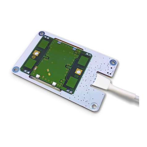
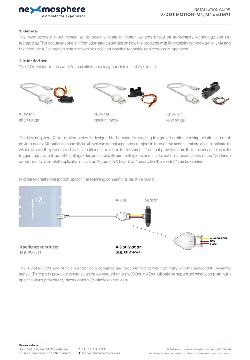
Nexmosphere X-EYE 200 Series User manual

1. General
The X-Eye Presence & Airbutton sensors can detect if a person is in front of the sensor and - if so - indicate the distance of
that person in relation to the sensor. Next to this, the sensor will provide an Airbutton trigger when a person places their hand
close to the sensor. This document provides explanation of the available functionalities and instructions on how to install and
integrate the sensor into your digital signage installation.
The information in this document is created for users who are familiar with the Nexmosphere API and are able to control a
basic setup with a Nexmosphere API controller. If this is not the case yet, please read the general documentation on the
Nexmosphere serial API rst.
2. Product overview
The X-Eye Presence & Airbutton sensors are available in 2 dierent models:
XY-240 XY-241
The shape of the models are dierent, please refer to the datasheets for mechanical dimensions.
The sensor specications are as follows:
Nexmosphere
Le Havre 136
5627 SW Eindhoven • The Netherlands
T+31 40 240 7070
Esupport@nexmosphere.com
PRODUCT MANUAL
© 2021 Nexmosphere. All rights reserved. v2.0 / 08-21
All content contained herein is subject to change without prior notice
1
Table of content
1. General 1
2. Product overview 1
3. Functionality and API commands 2
3.1 Presence & Airbutton detection 2
3.2 Absolute distance measurement 3
4. Installation requirements and guidelines 3
4.1 Laser safety considerations 3
4.2 Connection Diagrams 3
4.3 Hardware integration guidelines 4
5. Settings 6
5.1 Settings 6
5.2 Advanced settings: Field of View 7
5.3 Advanced settings: Output and error ltering 8
6. Quick test
XY-240 XY-241
detection range 0 - 250 cm 0 - 170 cm
beam angle 27° 27°
The X-Eye Presence & Airbutton sensors utilize InfraRed laser
emitters with an SPAD receiving array and Time-of-Flight technology
to measure the distance of a person or object in relation to the
sensor. The working principle is that the sensor emits photons which
are reected by the objects or persons in front of the sensor. The
reected photons are received by and an array of photodetectors. By
measuring the time of ight of the reected photons, the distance of
the person or object in front of the sensor is calculated.

© 2021 Nexmosphere. All rights reserved. v2.0 / 08-21
All content contained herein is subject to change without prior notice
Nexmosphere
Le Havre 136
5627 SW Eindhoven • The Netherlands
T+31 40 240 7070
Esupport@nexmosphere.com
2
The X-Eye Presence sensors provide the following functionalities:
1. Presence & Airbutton detection - detects if a person or object is present and indicates the detected distance zone
2. Absolute distance measurement - detects if a person or object is present and indicates the absolute distance in cm
When implementing distance zone triggers, consider the
following:
• For touchless input, a dedicated "Airbutton" detection
zone is available (AB). The detection range for the
Airbutton zone can be adjusted, please see page 6,
Settings.
• When no person is in front of the sensor, the distance
zone will be either XX (Out of Range) or the nearest
object in front of the sensor within its range. For
example if a wall is placed at 240cm of the sensor, the
detected distance zone will be 10 in case no person
is present.
• The "Range of Interest" which determines when an
object or person is Out of Range can be adjusted,
please see page 6, Settings.
The detected distance zone can always be request by
sending the following API command:
The reply will be identical to the triggered API messages
such as the examples listed above.
The X-Eye sensor divides its detection range into distance
zones of 25cm each. When a person or object in front
of the sensor moves into a new distance zone, an API
command is triggered, indicating the current distance
zone. This API message has the following format:
The following sections will cover each of these functionalities in detail. Please note that for each API example in this
document, X-talk interface address 001 is used (X001). When the sensor is connected to another X-talk channel,
replace the "001" with the applicable X-talk address.
**= distance zone 01-10 or AB or XX
X001B[Dz=**]
Zone XY-240
AB 0 -10 cm
01 10 -25 cm
02 25 - 50 cm
03 50 -75 cm
04 75 -100 cm
05 100 -125 cm
06 125 -150 cm
07 150 -175 cm
08 175 -200 cm
09 200 -225 cm
10 225 -250 cm
XX Out of Range
AB 01 02 03 04 05 06 07 08 09 10 XX
AB 01 02 03 04 05 06 07 08 09 10 XX
04
AB 01 02 03 04 05 06 07 08 09 10 XX
AB Air Button
Distance zone 04
Example commands
Person detected in distance zone 4 (75-100cm)
Person detected in distance zone 10 (225-250cm)
Out of Range, no person detected (>250cm)
Airbutton detected (0-10cm)
X001B[Dz=04]
X001B[Dz=10]
X001B[Dz=XX]
X001B[Dz=AB]
In the table below, the absolute distances for the default
distance zones are provided:
X001B[ZONE?]
Request current distance zone
Zone XY-241
AB 0 -10 cm
01 10 -25 cm
02 25 - 50 cm
03 50 -75 cm
04 75 -100 cm
05 100 -125 cm
06 125 -150 cm
07 150 -170 cm
XX Out of Range

© 2021 Nexmosphere. All rights reserved. v2.0 / 08-21
All content contained herein is subject to change without prior notice
Nexmosphere
Le Havre 136
5627 SW Eindhoven • The Netherlands
T+31 40 240 7070
Esupport@nexmosphere.com
3
Next to providing distance zone information, the X-Eye
sensor can also be set to provide absolute distance
measurements in units of 1 cm. This mode can be
activated by sending the following setting:
For debug and testing purposes, the sensor can also be
set to output raw sensor values in addition to the measured
distance. This mode can be activated by sending the
following setting:
***= distance in cm 000-250 or XXX
X001B[Dv=***]
X001B[Dr=distance:noise:signal:error]
X001S[4:2]
X001S[4:4]
Set trigger mode to abs. distance
Set trigger mode to raw values
When a person or object moves in front of the sensor, an
API command is triggered, indicating the current distance
zone. This API message has the following format:
In this mode, the sensor continuously sends out API
messages with the following format:
When implementing absolute distance measurement
triggers, consider the following:
• When no person is in front of the sensor, the distance
measurement will be either XXX (Out of Range) or the
nearest object in front of the sensor within its range.
• The required change in measured distance for a
new API message to be triggered is set to 10cm per
default. This value can be adjusted, please see page
6, settings.
distance in cm 000-500
noise level (kcps per 4 photodetectors) 000-999
signal level (kcps per 4 photodetectors) 000-999
error status 0-7
There are multiple settings available to set thresholds and
ltering levels based on the raw sensor values. For more
information on this please see page 8.
Example commands
Example commands
Person detected at 43cm distance
Distance 48cm, noise 37, signal 344, error 0
Person detected at 195cm distance
Distance 203cm, noise 35, signal 53, error 0
Person (or hand) detected at 7cm distance
Distance 274cm, noise 43, signal 19, error 7
Out of Range, no person detected (>250cm)
X001B[Dv=043]
X001B[Dr=048:037:344:0]
X001B[Dv=195]
X001B[Dr=203:035:053:0]
X001B[Dv=007]
X001B[Dr=274:043:019:7]
X001B[Dv=XXX]
The measured distance can always be request by sending
the following API command:
The raw sensor values can always be request by sending
the following API command:
The reply will be identical to the triggered API message
such as the examples listed above.
The reply will be identical to the triggered API message
such as the examples listed above.
X001B[DIST?]
X001B[RAW?]
Request current distance (cm)
Request current raw values

© 2021 Nexmosphere. All rights reserved. v2.0 / 08-21
All content contained herein is subject to change without prior notice
Nexmosphere
Le Havre 136
5627 SW Eindhoven • The Netherlands
T+31 40 240 7070
Esupport@nexmosphere.com
4
When integrating an X-Eye Presence & Airbutton sensor into your digital signage installation, several installation requirements
and guidelines need to be taken into account in order for the sensor to perform optimal and operate stable.
The X-Eye sensor can be connected to any X-talk interface and is therefore compatible with all Xperience controllers. Make
sure the X-Eye sensor is connected to the X-talk interface before powering the Xperience controller. Otherwise, it will not be
recognized by the Xperience controller and no sensor output will be provided.
The X-Eye Presence & Airbutton sensor contains a laser emitter and
corresponding drive circuitry. The laser output is designed to remain
within Class 1 laser safety limits under all reasonably foreseeable
conditions including single faults in compliance with IEC 60825-
1:2014 (third edition). The laser output power must not be increased
by any means and no optics should be used with the intention of
focusing the laser beam.
Caution: Use of controls or adjustments or performance of
procedures other than those specied in this document may result
into hazardous radiation exposure.
XN
DC Power supply
XC
Example connection to XC Controller Example connection to XN Controller
Field of View
The X-Eye Presence & Airbutton sensors have a Field of
View (FoV) of approximately 27°. Please take this into
consideration when designing your setup and determining
the position of the sensor. The sensors FoV can be
adjusted using advanced settings. Please see page 7, for
more information.
± 27° ± 27°

© 2021 Nexmosphere. All rights reserved. v2.0 / 08-21
All content contained herein is subject to change without prior notice
Nexmosphere
Le Havre 136
5627 SW Eindhoven • The Netherlands
T+31 40 240 7070
Esupport@nexmosphere.com
5
In environments with bright ambient light, the maximum detection range of the sensor can be less then 250cm. Due to this,
the sensor is not suitable for outdoor measurements and we recommend to place the sensor in such a way that it is not
directed perpendicular towards a window.
The level of ambient light can be measured by setting the sensor to raw data mode and reading the Noise level. The sensor
performs optimal when the ambient light level is less than 50 kcps (per 4 photodetectors).
The X-Eye Presence & Airbutton sensors are designed
in such a way that they do not interfere with each other.
Therefore it is possible to place multiple sensors side-by-
side with a small clearance in between of 15cm or more.
In case there is smudge or heavy dust on the sensor, the
sensor readings may become less accurate and unstable.
In this case, the sensor output will typically indicate a very
short distance between 1-10cm.
Light-coloured objects are easier to detect for the sensor
as these reect more IR signals than dark-coloured
objects. In practice, this means that the maximum
detection distance at which a person can be detected
by the sensor may vary depending on the colour of the
clothing the person is wearing.
Both the XY-240 and XY-241 can be installed behind a front panel with a cut-out. The XY-241 has an embossed cylinder
of 9.8mm diameter. We recommend to make a circular cut-out of 10mm diameter in the front panel through which the
embossed cylinder can be placed. In this case, the thickness of the front panel should not exceed 5mm. In case of installing
the XY-240, the same circular cut-out and alignment can be applied. Alternatively, the XY-240 can be placed in a cut-out
which t the dimensions of the entire sensor outline.
sensor
sensor

© 2021 Nexmosphere. All rights reserved. v2.0 / 08-21
All content contained herein is subject to change without prior notice
Nexmosphere
Le Havre 136
5627 SW Eindhoven • The Netherlands
T+31 40 240 7070
Esupport@nexmosphere.com
6
The X-Eye sensor has multiple settings which determine the behaviour and output of the sensor. The settings can be adjusted
by sending X-talk setting commands via the API. After a power cycle, the settings always return back to default.
X001S[1:1]
X001S[7:1]
X001S[9:1]
X001S[20:1]
X001S[7:5]
X001S[9:5]
X001S[4:1]
X001S[4:3]
X001S[5:X]
X001S[6:X]
X001S[8:X]
X001S[1:2]
X001S[7:2]
X001S[9:2]
X001S[20:2]
X001S[21:X]
X001S[7:6]
X001S[9:6]
X001S[4:2]
X001S[4:4]
X001S[1:3]
X001S[7:3]
X001S[9:3]
X001S[7:7]
X001S[1:4]
X001S[7:4]
X001S[9:4]
X001S[7:8]
Setting 1: Status LED behaviour
1. LED on
2. LED o
3. LED on, blink at trigger (default)
4. LED o, blink at trigger
Setting 7: Sample averaging (advanced)
1. No averaging (default)
2. Running average of 2 samples
3. Running average of 3 samples
4. Running average of 4 samples
5. Running average of 5 samples
6. Running average of 6 samples
7. Running average of 7 samples
8. Running average of 8 samples
Setting 9: Sensor measurement duration (advanced)
1. 20mS
2. 33mS
3. 50mS
4. 100mS
5. 200mS (default)
6. 500mS
Setting 20: Airbutton zone enable / disable
1. Disable Airbutton zone
2. Enable Airbutton zone (default)
Setting 4: Output mode
1. Distance zone triggers (default)
2. Absolute distance change triggers
3. No triggers, use data requests
4. Raw data mode, continuous data
Setting 5: Change in absolute distance for trigger
Set trigger distance
Setting 21: Airbutton zone range
Set range Airbutton zone
Setting 6: Range of Interest
Set Range of Interest
Setting 8: Hysteresis for distance zones
Set hysteresis threshold
X is a value between 1-250 and its default value is 10. It
indicates the required change in measured distance for an
API output message to trigger when the sensor is set to
absolute distance mode (setting 4:2).
X is a value between 1-250 and its default value is 10. It
indicates the range of the Airbutton zone in cm, starting at
0. For example, when set to 10 (default), the Airbutton zone
is dened as 0-10cm.
X is a value between 1-50 and its default value is 25 ( X Y-
240) and 17 (XY-241). It indicates the sensor's range of
interest in units of 10cm, so the default range of interest
is 250cm (XY-240) and 170cm (XY-241). If an object is
detected at a longer distance than the Range of Interest,
it is considered to be Out of Range, which will be indicated
as such in the output message. For more info, please see
section 3, page 2 and 3.
This setting determines the number of samples which are
averaged to determine the sensor's output. The higher the
number of samples, the less responsive the sensor will be
to change, but also the more stable in case of challenging
environments. The lower the number of samples, the more
responsive the sensor will be to change. Please note that
typically this setting does not need to be adjusted.
This setting determines the duration of one measurement
cycle. The higher the duration, the higher the maximum
detection distance and the better the repeatability of the
sensor's output. The lower the measurement duration, the
faster the sensor will detect a change in detected distance,
but the less stable the output will be and the lower the
maximum detection distance will become. Please note
that typically this setting does not need to be adjusted.
When Airbutton zone is enabled, the sensor will output
Dz=AB when an object or hand is detected within the
Airbutton zone (default 0-10cm). When the Airbutton zone
is disabled, the default distance range allocated for the
Airbutton zone (0-10cm) will be added to distance zone 1.
X is a value between 1-50 and its default value is 25. It
indicates the hysteresis threshold in millimetres for a new
API message to be triggered when the sensor is set to
distance zone mode (setting 4:1). This setting can avoid
an overload of API messages jumping back and forth
between two adjacent distance zones when a person is
standing at the edge of two distance zones. The lower
the X value, the less change in distance is required (with
the previous measured distance) for the sensor to output
a new distance zone. Vice versa, the higher the X value,
the more change in distance is required for the sensor to
output a new distance zone.
For more info, please see section 3, page 2 and 3.

© 2021 Nexmosphere. All rights reserved. v2.0 / 08-21
All content contained herein is subject to change without prior notice
Nexmosphere
Le Havre 136
5627 SW Eindhoven • The Netherlands
T+31 40 240 7070
Esupport@nexmosphere.com
7
The following settings provide advanced control over the sensor's Field of View (FoV). Adjusting these settings can cause the
sensor to stop being able to make accurate measurements. After a power cycle, the settings always return back to default.
The sensor has a 16x16 grid of SPAD photodetectors. Per default, the detection values of all 256 SPAD's are used to measure
the distance of the object or person in front of the sensor. By disabling part of the 16x16 grid, it is possible to make the Field-
of-View angle smaller or ignore a specic section of the Field-of-View. Typically these settings are used when the sensor's
FoV is obstructed with objects which should be ignored. For example when the sensor is installed in the back wall of a retail
shelf and the shelf is partially in the sensor's FoV.
X is a value between 4-16 and its default value is 16. It
determines both the number of "columns" and "rows"
and will auto-centre the Field of View. Please note
that decreasing the grid size can cause the maximum
detection distance to decrease. When setting the grid size
to its minimum setting (4x4), the FoV will be approximately
15°. At the default maximum setting (16x16), the FoV is
approximately 27°.
The centre anchor in case of an even number of columns or rows is the
rst cell to the right/top of the middle row and cell. Therefore with the
default 16x16 grid, the centre anchor is cell 9,9. In case of an odd number
of columns or rows, the centre anchor is the middle row and column.
X is a value between 4-16 and its default value is 16. It
determines the number of active "columns". Decreasing X
will make the FoV less "wide".
X is a value between 4-16 and its default value is 16. It
determines the number of active "rows". Decreasing X will
make the FoV less "high".
X is a value between 3-15 and its default value is 9. It
determines where on the grid the X-location of the centre
anchor of the FoV is
located.
X is a value between 3-15 and its default value is 9. It
determines where on the grid the Y-location of the centre
anchor of the FoV is
located.
Example: when setting
10 is set to 8 (10:8), the
FoV will be as indicated
in the image on the right.
Example: when setting
11 is set to 8 (11:8) and
setting 12 is set to 5
(12:5) the FoV will be as
indicated in the image
on the right.
Example: when setting
13 is set to 12 (13:10)
and setting 14 is set to
11 (14:11) the FoV will
be as indicated in the
image on the right.
columns
rows
backside
sensor
9,9
1
1
2
3
4
5
6
7
8
9
10
11
12
13
14
15
16
2 3 4 5 6 7 8 9 10 11 12 13 14 15 16
Setting 10: FoV quick adjust (square grid, auto-centre)
Set active grid size
Setting 11: Number of active columns
Set number of active columns
Setting 13: Number of active rows.
Set number of active columns
Setting 12: Set X-location centre anchor
Set X-location centre anchor
Setting 14: Set Y-location centre anchor
Set Y-location centre anchor
X001S[10:X]
X001S[11:X] X001S[13:X]
X001S[12:X] X001S[14:X]
9,9
5,9
9,11

© 2021 Nexmosphere. All rights reserved. v2.0 / 08-21
All content contained herein is subject to change without prior notice
Nexmosphere
Le Havre 136
5627 SW Eindhoven • The Netherlands
T+31 40 240 7070
Esupport@nexmosphere.com
8
The following settings provide advanced control over the sensor's lter settings and error handling which determine the
requirements for a sensor reading to be considered valid. Next to that, they provide control over the output format. Please
note that typically these settings do not need to be adjusted. Within these settings, the following parameters are utilized:
Signal Level: indicates the level of the measurement signal in Kcps (kilo counts per second) per 4 SPAD's.
The higher the Signal Level, the higher the accuracy of the measurement.
Noise Level: indicates the level of the background noise in Kcps (kilo counts per second) per 4 SPAD's. The higher the background noise, the less accurate
the measurements will be, especially at higher distances. Background noise is typically caused due to a high amount of ambient light, such as sunlight shining
through a window.
Error status: the sensor can provide several status levels, each indicating a specic type of warning or error:
0No error or warnings
1 Warning: repeatability or standard deviation of the measurements is bad due to a decreasing signal/noise ratio
2 Warning: the return signal may be too weak to do a accurate measurement
Likely causes are that the target is too far away, the target is not reective enough (e.g. dark clothing) or that the target is too small
3 Warning: there may be a target "out of bounds" which could result into inconsistent measurements
Typically this occurs when a bright target is placed at +/- 5 meters of the sensor
4 Error: there is a target "out of bounds" which likely results into inconsistent and inaccurate measurements
Typically this occurs when a very bright target is placed between 5-6 meters of the sensor.
5 Error: the Signal/Noise ratio is lower than the set minimum (see setting 15)
6 Error: the minimum signal level is lower than the set threshold (see setting 16 and 17)
7 Error: the measured distance is longer than the set Range of Interest (see setting 6, page 6)
8 Error: the signal level is too low for the short distance measured. Typically this occurs when the sensor is aimed at a void.
The signal level, noise level and error status can be accessed by setting the sensor to Raw Data mode. Please see page 3 and page 6 (setting 4).
X is a value between 1-250 and its default value is 50. It
determines how much noise there can be in relation to the
signal level for the measurement to be considered valid. X
sets the noise ratio value in steps of 0.1. Some examples:
When X is set to 5, the Signal/Noise ratio is 1 : 0.5
When X is set to 10, the Signal/Noise ratio is 1:1
When X is set to 50, the Signal/Noise ratio is 1:5 (default)
When X is set to 100, the Signal/Nosie ratio is 1:10
X is a value between 1-250 and its default value is 120.
It determines the minimum signal level (per 4 SPADs) for
a measurement of 0cm to be considered valid and not
categorized as error status 6. The higher the minimum
signal level, the better the signal needs to be for a
measurement to be considered valid. Decreasing this
setting can cause for ghost measurements when the
sensor is directed toward a void.
X is a value between 1-250 and its default value is 15. It
determins the minimum signal level (per 4 SPADs) for a
measurement of >100cm to be considered valid and not
categorized as error 6. Increasing this setting can cause
the maximum detection distance to shorten.
Setting 15: Minimum Signal/Noise ratio
Set minimum signal-noise ratio
Setting 16: Minimum Signal level for 50cm distance
Set minimum signal level for 0cm
Setting 17: Minimum Signal level for >150cm distance
Set minimum signal level for 150cm
X001S[15:X]X001S[18:1]
X001S[19:1]
X001S[18:2]
X001S[19:2]
X001S[18:3]
X001S[19:3]
X001S[18:4]
X001S[19:4]
X001S[18:5]
X001S[19:5]
X001S[19:6]
X001S[16:X]
X001S[17:X]
Setting 18: Error status ltering (for Error status 1-4)
1. No readings are blocked
2. Readings w/ error 4 blocked
3. Readings w/ error 3-4 blocked
4. Readings w/ error 2-4 blocked
5. Readings w/ error 1-4 blocked (d)
Setting 19: Error output format (for Error status 5-8)
1. Send XX in case of error 7-8 (def)
2. Send XX in case of error 6-8
3. Send XX in case of error 5-8
4. Send XX in case of all errors
5. Send X + error number
6. No output for all errors
When a reading is blocked, it won't be used for any output,
except Raw Data mode.
enlarged image available on next page
Default, the sensor will provide XX as distance zone output
in case of error 7. In case of error 5 and 6, there will be
no output. This setting can be used to adjust the output
behaviour for the dierent error levels.
0 50
Measurement (cm)
Signal level (Kcps)
100
100
200
300
150 200 250 300
Error
status 6
OK
setting 16
setting
25 & 26
setting 17
Error
status
8

© 2021 Nexmosphere. All rights reserved. v2.0 / 08-21
All content contained herein is subject to change without prior notice
Nexmosphere
Le Havre 136
5627 SW Eindhoven • The Netherlands
T+31 40 240 7070
Esupport@nexmosphere.com
9
X is a value between 1-250 and its default value is 50. It
determines the maximum distance in cm for which an
Error 8 can occur, so the default maximum distance for an
Error 8 is 50 cm. This setting also determines the minimum
distance for an Error 6 to occur. The minimum distance for
Error 8 is xed at 0cm.
X is a value between 1-250 and its default value is 120.
It determines the maximum signal level (per 4 SPADs) for
a measured distance lower than the maximum distance
indicated in setting 25 to be considered as an Error 8.
Setting 25: Maximum distance for Error 8
Set max distance for Error 8
Setting 26: Maximum signal level for Error 8
Set max signal level for Error 8
X001S[25:X] X001S[26:X]
0 50
Measurement (cm)
Signal level (Kcps)
100
100
200
300
150 200 250 300
Error
status 6
OK
setting 16
setting
25 & 26
setting 17
Error
status
8
Error 8 occurs when the sensor is aimed at a void. As this is independent of most other parameters of a setup, setting 25 and
26 typically do not need to be adjusted.

6. Quick test
In order to test if the X-Eye Presence & Airbutton sensor is installed correctly, please follow the test procedure below:
© 2021 Nexmosphere. All rights reserved. v2.0 / 08-21
All content contained herein is subject to change without prior notice
Nexmosphere
Le Havre 136
5627 SW Eindhoven • The Netherlands
T+31 40 240 7070
Esupport@nexmosphere.com
10
Step 1 - Setup
First, connect the X-Eye sensor to an Xperience
controller. Secondly, power the Xperience controller.
The green status LED of the X-Eye sensor should go
on. The status LED of the controller will start to blink
and once power-up is completed will be lit continuously
Step 2 - Test detection
Stand +/-30cm in front of the X-Eye Presence sensor.
Both the green status LED of the sensor and the status
LED of the controller should blink.
Move in perpendicular direction towards or away
from the sensor
Both the green status LED of the sensor and the status
LED of the controller should blink each time your enter
a new distance zone.
For a full test we recommend to connect the setup to
a mediaplayer or PC and test all API commands listed
in this document (see section 3, page 2-3). For more
information on how to setup a test for your controller,
please see the Quick Start Guide of the Xperience
controller you are using. These are available on
nexmosphere.com/support-documentation
Please contact support@nexmosphere.com for any
support questions you may have.
In case any of the steps above does not provide
the expected result, please check the installation
guidelines in this document.
XN
Connect to powered
USB port
sensor
XN
LED BLINK
LED BLINK
This manual suits for next models
2
Table of contents
Other Nexmosphere Accessories manuals
Nexmosphere
Nexmosphere XS Series User manual
Nexmosphere
Nexmosphere XF-P3W User manual
Nexmosphere
Nexmosphere XZ Series User manual

Nexmosphere
Nexmosphere XD Series User manual
Nexmosphere
Nexmosphere X-EYE XY-510 User manual
Nexmosphere
Nexmosphere XT-EF Series User manual
Nexmosphere
Nexmosphere X-EYE XY-116 User manual
Nexmosphere
Nexmosphere XZ-A40 User manual
Nexmosphere
Nexmosphere XE Series User manual

Nexmosphere
Nexmosphere XV User manual
