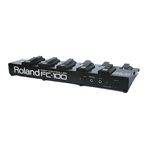
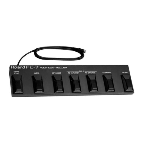
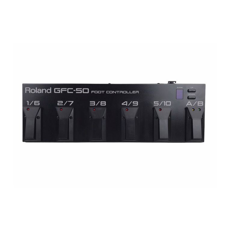
Roland FC-100mkII User manual

Ik
i i)Roland
IM·!I
FOOT
CDNTnOLLEn
Owner's
Manual

2
Thank you
for
purchasing the Roland
FC-1
OOMK
II
can
be
connected to any instrument featuring
an
RRC
(Roland Remote
Cantrall
IN
socket.
Please
read
this owner's manual carefully,
FEATURES
The
FC-1
OOMK
IT
is
agreatly enhanced version
of
the
FC-100
foot controller,
By
connecting the optional
RRC
TO
MIDI Converter
(RMC-lI. the FC-l00MK
IT
can
be used
as
an
all-purpose
MIDI foot controller, which provides pedal control over
transmission
of
any
Program Change to a connected
MIDI
devtce.
The FC-l0CMK
IT
allows you to make a whole range of
setting, including the MIDI channel,
and
Control Numbers
for the all-purpose pedal unit or expression pedal.
Using
MiD)
messages
(System
Exclusive),
the
settings
for,
and
operation
of
each
pedal
can
be
individually
controlled
from
an
external
MIDI
device.
CONTENTS
• IMPORTANT
NOTES
"""""",,,,,,,,,,,,,,,,,,,,,,,,,,,,,,,,,,,, 3
[jJ
Panel
Description
"""""""",,,,,,,,,,,,,,,,,,,,
4
I2J
How
to
use the FC-l00MK II
""""""""""",,,,,,,,,
""
5
1,
RRC
Foot
Pedal
Mode
""'"''''''''
'"''
"
""
,
'"
5
2,
MIDI Foot
Pedal
Mode
CiJ
RRC
Foot
Pedal
Mode
1,
Setup Examples
,""""
,
"",,"",,'"
2,
Mode Setting
""""''''
3,
Operation ",,',,'"
a.
Patch
Selection
b,
Control
Pedal
""
''''',,'''',,''
c,
Expression
Pedal
""
IAl
MIDI Foot
Pedal
Mode
1,
Setup Examples
2,
Mode Settings
"'"
a,
MIDI
Mix
On/Off
b,
MIDI Channei
,""'"
c,
OMNI On/Off
"""
d,
Control
Numbers,
3,
Restoring the Factory Preset Data
'"
4,
Operation
","",,""
a,
Patch
Selection"
b,
Control Pedal,,,,
c.
Expression
Pedal
llij Using Exclusive Messages
1.
Concerning
Modes,
2,
About the
RRC
Mode,
llil Reference
"","",,"
5
''',''
6
,,,"
6
..
............ 7
,7
, 7
,8
,8
,9
9
"'" 10
""'"
10
"'''"
10
""
10
",,"
10
""
13
",,'" 14
"'"
14
'"
"""
16
'"
, 16
,,","
17
"""
17
'"
18
",'"
19
1,
Table
of
data which
can
be
edited "'"
"'"''
"'"''
19
2,
Factory Preset Data,
3,
Troubleshooting
'"
About Roland Exclusive Messages
MIDI Implementation Chart
""
MIDI Implementation
• SPECIFICATIONS
'"'''''''',,'','',,'''',,'''
..
19
"
"'"
20
"""
21
,,,"
25
""
26
30
Please read
the
separate "MIDI" before reading this owner's manual.
Copyright © 1988 by ROLAND CORPORATION
All rights reserved, No part
of
this publication may be reproduced in
any form
without
thewritten permission
of
ROLAND CORPORATION,

IMPORTANT NOTES
I
Concerning
placement
I
•
Avoid
using
or
storing
the
unit
in
the
following
places,
as damages could result.
o Places
subject
to
extremes
in
temperature.
(Such as
under direct sunlight, near heating units, above
equipment
generating heat. etc.)
o Places near
water
and moisture. (Baths, wash-
rooms,
wet
floors, etc.) Places
otherwise
subject
to
high huidity.
o
Dusty
environments.
o Places
where
high levels
of
vibration are produced.
Maintenance
I
• For everyday cleaning,
wipe
the unit
with
a
soft
dry
cloth,
or
one
that
is
dampened
slightly.
To
remove
dirt
that
is
more
stubborn,
wipe
using a mild, neutral deter-
gent.
Afterwards,
make sure
to
wipe
throughly
with
a
soft
cloth.
• Never apply benzene, thinners. alcohol
or
any like agents,
to
avoid the risk
of
discoloration and deformation.
Concerning
memory
backup
I
• Please be aware that
the
contents
of
memory
may
at
times
be lost;
when
sent
for
repairs or
when
by
some
chance a
malfunction
has occurred.
Important
data
srould
be
written
down
on paper. During repairs, due
care
is
taken
to
avoid
the
loss
of
data, however, in
certain cases, such
as
when
circuitry related
to
mem-
ory itself
is
out
of
order,
we
regret that it
may
be
impossi-
ble
to
restore
the
data.
Ohter
Precautions
I
•
Protect
the
unit
from
strong impact.
• Avoid
getting
any foreign objects (coins,
wire,
etc.), or
liquids (water, drinks, etc.) into the unit.
•
Before
using
the
unit
in a foreign country, check
first
with
your
local Roland Service Station.
•
At
any
time
that
you
notice
a malfunction,
or
othervvise
suspect
there
is damage,
immediately
refrain
from
using
the
unit. Then
contact
the
store
where
bought,
or
the
nearest Roland Service Station.
In
the
event
that
your
instrument
must
be
returned
for
service,
it
should
be
returned
together
with
the
connection
cable and
the
host
unit. The
problem
may
outside
the
unit.
3

4
III
Panel
Descriptions
«
Rear
Panel»
Rol
d
FOOT
CONTROLLER
an
FC-1DDMKlI
«Front
Panel»
FC·1OD
.....
R
~~~
~
~
~
[Et]
~
~
I 1
o RRC
OUT
Socket
Connect this
with
the
RRC
IN Socket
of
an
external device
using
the
supplied
RRC
cable.
f)
Expresion
Pedal
Jack
1 (EXP1)
Connect an expression pedal to this jack. The expression
pedal
will
function
differently
depending
on
the
external
device
and specific
settings
you use.
...
Be sure to use a Roland
EV~5
Expression Pedal or BOSS
EV~
10.
Use
of
other
pedals
may
in certain cases
not
allow
for
normal operation.
e
Tuner's
Signal
Out
Jack
Connect a tuning
unit
(such
as
BOSS TU-12)
to
this jack.
...
This jack
becomes
inactive
when
an
RMC~
1 (optional)
is
connected.
e
Mode
Selector
Switch
This
selects
how
the
Control
PedalO
will function.
o
Expression
Pedal
Jack
2 (EXP2)
Connect an expression pedal
to
this jack. The functions
available
will
vary depending on the particular pedal and
specific
settings
you use.
G
Number
Pedals
(1
-8)
Use
these
pedals
for
selecting relevant numbers.
I
1
OJ
<0
o e e o
n
~
e=
V
.-,
~~
~
-
Llo
r---.
'==
I
~
~
I
tID
0
8
Number
Indicators
(1
-8)
The indicator for the number currently selected will light
up.
o
Bank
Pedal
Provides for selection
of
the bank.
o
Control
Pedal
This pedal will function
in
a variety
of
ways, depending
on the
type
of
device connected and the settings
that
are made.
«ri>
Control
Indicator
This
shows
the
current status
of
the Control Pedal C).
Q)
Bank
Display
This indicates the bank currently selected.
o
Group
Pedal
Use this
for
selecting a group.
@)
Group
Indicator
(A/B)
The indicator
for
the
group currently selected
will
be
lit.
CD
Point
This
shows
the
current
Mode
and the
On/Off
state
of
MIDI Mix.
* The above explanation
of
pedal functions applies to
normal pedal operations.

[2]
How
to
use
the
FC-100MK
II
1.
RRC
Foot
Pedal
Mode
2.
MIDI
Foot
Pedal
Mode
The
FC-l00MK
IT
features
two
Foot Pedal
Modes;
the
RRC
Foot
Pedal and
MIDI
Foot Pedal
modes.
Select
the
one
that
suits
your
purpose.
Select this
mode
for
connecting the
FC-100MK
II
with
devices featuring
an
RRe
IN connector. The FC-100MK
II
can
be connected
to
any device
which
is
compatible
with
the
FC-l00.
To
use
the
RRC
Foot
Pedal
Mode
...•.
Refer
to
"00
RRC
Foot
Pedal
Mode"
on
page
6.
Select this
mode
for
controlling
MIDI
devices, in combination
with
the
RRC
TO
MIDI
Converter
(Roland
RMC-l:
optionali.
This
mode
allows
you
to
make
changes in
settings
related
to
the
following:
MIDI
Mix
On/Off
MIDI
Channel
OMNIOn/Off
Control
Number
Control Pedal
Expression Pedal
To use
the
MIDI
Foot
Pedal
Mode
.....
Refer
to
"IAJ
MIDI
Foot
Pedal
Mode"
on
page
9.
*
Whenever
you
connect
an
RMC-1
to
the
FC-100MK
II,
be
sure
to
set
the
Fe-l00MK
IT
to
the
MIDI
Foot
Pedal mode.

6
[3J
RRC
Foot Pedal
Mode
1.
Setup
Examples
I:n"
1'·0"=
RRC
IN
SIGNAL
OUT
R
RC
OUT
::XP; I
FC·lXJ_lI
~~\TI1
~
Select
mode
for
connecting
the
FC~
1
OOMK
IT
to
devices equipped
with
an
RRC
IN
Socket.
This mode allows you to select patches, or use the Control Pedal and
Expression Pedal
for
control.
Two
expression pedals can
be
connected
at
the
same
time.
* The expression pedal jack
2.,
(EXP2)
cannot
be used
with
certain
types
of
devices that you
might
wish
to connect.
Ill!':
111,10
01
~
Device featuring the
RRC
IN
socket. such
as
GP-B.
Mode Selector Switch
~
laJ
lr]
..
~.
iEil
I~I
n~~;;i
[j
1aJ
~
lDJ
~
[5J
iO.'llji~
[;f-
....
'-",~,;
r"~
I.
"
"j"
I
[i3,~.
__
-
,4~(
"';'1k,!
I~'~~
.
..!
',i
'"
!i'li
o 0
1"1~i-',
'hl"'~
FC-1
OOMK
II
Tuner EV-5
If- Set the position
of
the
Mode
Selector Switch0
as
explained
in
the
owner's
manual
for
the dev'lce
to
be connected
to
the FC-l00MK
ll.
*
When
connecting
RRC
cable, be sure
to
connect
the
IN socket on one
unit
to
the OUT
socket
on
the
other
unit. Do
not
connect
IN
to
IN
or
OUT
to OUT.
* Be sure to
cannot
the
RRC cable securely, until it locks in place,

2.
Mode
Setting
[HOW)
3.
Operation
a.
Patch
Selection
[STEP 1)
Once
the
connections
are
completed,
set
the
Fe-100MK
II
to
the
ARC
Foot
Pedal mode.
Switch
on
the
unit
connected
to
the
FC-100MK n
while
holding
the
Group
Pedal@)
down
.
...
Be
sure
use
the
switch
on
the
connected
unit
for
turning poweF
on
or
off.
Power
On
~~
~
~
~
..
~
,
IS:::::
r--.:.-
'0
~
[!]
~
~
~
~
I
Goes
out
Group Pedal
When the Fe-!
OOMK
II
is
set
to the
RRC
Foot Pedal mode, the Point
tD
will
go out.
*
Once
the Fe-100MK
II
is set
to
the
RRC
Foot Pedal mode,
it
will
auto-
matically
default
to
the
RRC
Foot
Pedal
Mode
at power-up,
without
need
for
holding
the
Group Pedal
down
.
...
The Fe-100MK
IT
is
set
to
the
RRC
Foot Pedal
mode
when
it
leaves
the
manufacturer.
A Patch is a
program
number
for
an external device. It is
represented
by
Group, Bank and
Number.
There are a total
of
128
Patches ava:lable
for
selection.
-I<
A Patch
is
normally displayed
in
the same
way
as on
the
connected device.
However,
the
initial display at
power-up
will be Group A, Bank 1 and
Number
1.
To
select
a Patch, do
as
follows.
Select a Group.
Press
the
Group
Pedal0
to
select
Group A or
B.
The Group Indicator@}
for
the selected group
will
light
up.
Group Indicators
I
,
~~
~
~
~
~
Ilr
~
~
~ ~
~
[]
Group Pedal
7

[STEP
21
[STEP
31
b.
Control
Pedal
c.
Expression
Pedal
8
Select a Bank.
Press
the
Bank
Pedale
and confirm
that
the Bank DisplayCi) is blinking.
Then press a relevant
Number
Pedal 0
to
select
the
Bank you
want.
The
selected Bank is
shown
in
the
Bank DisplayeD.
~~lfil
~
~ ~
lQ1
ral-
t--
2.
The Bank Display
flashes.
~
U]
~
I [j
.~
~
I I
L-l,
Press
the Bank
Pedal.
I
3. Select a Bank using the relevant
Number
Pedal.
Press
the
relevant
Number
Pedal.
*
To
cancel
the
Bank selecting mode, press
the
Bank Pedal
(l)
while
the
Bank DisplavG) is blinking.
Select
a
Number.
Press
the
relevant
Number
Pedal.
to
select the
Number
you
want.
The
corresponding
Number
IndicatorG
will
light
up.
i
Press
the
Number
Pedal
that
you
wish
to select.
The Control Pedal functions differently depending on the type
of
device you
use. Read
the
owner's
manual
for
the
device, and
if
necessary, change
the
position
of
the
Mode
Selector
Switch
e
on
the
rear of
the
unit.
*
When
the
Mode
Selector
SWitchO
is set
to
the
"I"
position and the Control
PedalO
is
turned
on,
selecting
a Patch
will
automatically
turn
off
the
Control Pedal
f).
Two
expression pedals can be
connected
to the Expression Pedal Jacks
IEXPl
e and
EXP201
at
the
same
time.
* The EXP2 0 jack cannot
be
used
with
some
types
of
devices.
*
Depending
on
the
external device you use, the expression .pedal
will
function
differently. Read
the
owner's
manual for the relevant unit.

[II
MIDI
Foot Pedal
Mode
1.
Setup
Examples
Select this
mode
for connecting the FC-l00MK n
to
MIDI equipped devices
via the Roland RMC-1 (optional). From this
mode
you can
select
patches.
or use the Control Pedal
or
two
expression pedals. An expansive range
of
controls can be achieved through variations in settings.
AC
Adaptor
PSA-120, 220
or
240 (Optional)
MID:
OUT
MIOI
IN
lOUT
Fe-,
DOMK
IT
FC-100MK n
MIDI
MIX:
DFF EV-5
The Fe-100MK
II
can
crontrol a sound module or keyboard. If you
connect
the MIDI OUT socket
on
the external
instrument
to the MIDI
IN
on
the
RMC-1, the display
of
the
Fe-,
OO~K
1I
will match
that
of
the external device.
(Set the
FC-100MK
II to MIDI MIX
Off
as
explained
in
the following section.)
MIDI
OUT
RRC
IN
iB
AC
Adaptor
PSA-120, 220
or
240
(Optional)
(Optional)
MIDI
MIX:
ON
L!
___
L-.sOL-,!;~-->!_-.!~U
The
FC·100MK
II
ca[l also control a sound module that
is
at
the same
time
being controlled
by
a sequencer. (Set
the
FC-tOOMK
IT
to MIDI MIX On as
explained in
the
following section.)
*
When
connecting
RRC
cable, be sure
to
connect the IN
socket
on one
unit
to
the
OUT socket on
the
other
unit. Do
not
connect
IN
to
IN
or
OUT
to
DUT_
*
Be
sure
to
connect the
RRC
cable securely, until
it
locks
in
place.
9

2.
Mode
Settings
a.
MIDI
Mix
On/Off
b.
MIDI
Channel
c.
OMNI
On/Off
d.
Control
Numbers
[STEP
1]
70
To
use the
FC·l00M'
IT
in
the
MIDI
Foot Pedal mode. you
must
first
make
settings for
the
follow'lng:
You
can
select either MIDI
Mix
On
or
Off. MIDI Mix On mixes the messages
from
MIDI IN (RMC·1) and
those
of
the Fe·100M'
IT
and sends the
mixed
data
from
MIDI OUT (RMC-l). MIDI
Mix
Off
sends only the
FC-l00M'
IT's
data from the MIDI OUT
on
the
RMC-l.
* For detailed explanation, see
"MIDI
Implementation"
on
page 26.
Set the MIDI channel
of
the
FC-1
OOMK
II
to
the same number as
the
external
device so
that
the messages can be received and transmitted.
You
can
select
OMNI
On or Off.
At
OMNI
On, all MIDI messages (except
for
Exclusive messages)
on
all
channels are received regardless
of
which
MIDI
channel
is
selected. At OMNI Off, only the messages
on
the set MIDI channel
will be reeieved.
* The
FC-100MK
nalways
transmits
messges only on the set MIDI channel.
Control numbers need
to
be assigned to
the
Control
Pedal0
and
expression
pedalse
and
0·
Be
sure to
set
the parameters
in
the
order shown, that
is,
a,
b. c then d.
After
you have finished making the settings, switch on the
unit
without
pressing the pedal, and it wiil be set
to
the
MIDI Foot Pedal mode. The set-
tings you have made w'lIl
be
retained even after the unit
is
switched
off.
Set MIDI
Mix
to On or Off.
o To set
to
MIDI
Mix
On
Turn
on
the
power
while
holding both the Bank Pedal«i) and Control Pedal G
down.
o
To
set
to
MIDI
Mix
Off
Power
On
The current
MIDi
channel and
OMNI
state are
shown.
L
L-
Control Pedal
Bank Pedal
Turn
on
the
power
while holding the Control Pedal
f).
Power On
The current
MIDI
channel and
OMNI
state are
shown.
* Be sure to use the
switch
on
the
connected device (RMC-1)
to
turn
power
on
or off.

[STEP
2]
[STEP
3]
[STEP
4]
Set
the
MIDI
channel
*
If
you
do
not
need to change
MIDI
channels and OMNl, skip this
step
and
go
to
step 3.
Press
the
Number
PedalO
and Group
Pedalf)
that
corresponds
to
the
MIDI channel you want. The indicators represent MIDI channels
as
shown
below.
Number
I I 2 3 I 4
Group A I I 2 3 4
Group B 9 I
10
II
12
Group
Inidcators
~o~fnJ
~
It]
~
~
I
IS'
~
~ ~ ~
. ,
[fl
~-
I ,
,
Number
Pedals
5
5
13
1--
6 7
6 7
14
15
Group Pedal
Blink
I 8
I 8
I
16
..
If
you
do
not need to change the status
of
OMNI OnlOff, press the Control
Pedale;)
then
go
to
step
4. (Skip
step
3.)
1)
Press the Bank Pedal 0
to
select
OMNI
On
or
Off.
OMNI
B
/C,
[1]
~
IT]
~
~
~~~~Tj
"
(8(1----
ON
OFF
[1J
~
~
,r]
~
~
Blink
lUJ
lU
T
Bank Pedal
2)
Press
the
Control
Pedal0,
then
go
to
step 4.
1)
Using the Number Pedals 0:
(1
-
4),
change the Control
Numbers
shown
in
the
Bank Display
•.
*
If
you do
not
need
to
change
the
Control numbers, press
the
Control
Pedale;) and go
to
the
next
step.
2} Press
the
Control
PedalO
to
finalize the setting.
7 7

72
[How
to
set a Control
Number]
+10
-10
+1
-1
The value assigned
to
the above Control Pedal
(1
-4)
is
added to
(+
value)
or subtracted from
(-
value)
the
current control number.
* a
to
95 are valid
for
a control number. Any number higher than
96
is
automatically substituted by 95.
(Control
Pedal
(in
Latch
mode:
see
page
15.)
[J=;>[[]=;>Gc;>[6Jc;>[5J~D
Control Pedal Latch Control Number: 65
1\
I < I
<===D
({
Determined
by
Control
Pedal,,})
~
(The value
is
displayedl
(Control
Pedal
(in
Unlatch
mode:
see
page
15.)
rFlltllDrElfUlD
~=;>~=;>OC;>[QJC;>LtJ~
Control Pedal Unlatch Control Number:
64
i\
I < I
<===D
{(
Determined
by Control Pedal
f))
~
(The value
is
displayedl
(Expression Pedal
1)
1El=~J'lc;>Oc;>rFilc;>[]]1
~D
lQL!JD~
'.
Expression Pedal 1 Control Number: 7
1\
I < I
<===D
{(
Determined
by
Control Pedal
0})
~
(The value
is
displayedl
(Expression Pedal
2)
rEl
[2]1
0
rFil
OJ
0
l£Jc::::t>
C
c;>Oc;>~c;>
'.
~
Expression Pedal 2 Control Number: 1
1\
I < I
<===D
{(
Determined
by
Control Pedal O})
~
(The value
is
displayedl
I
MIDI
Foot Pedal
Mode
I

[Important]
3.
Restoring
the
Factory
Preset
Data
[STEP 1]
[STEP
2]
Now,
the
Pointe
shows
the
current MIDI
Mix
status, and
the
FC-1
OOMK
II
is
in the
MIDI
Foot Pedal mode.
MIDI
Mix
ON
OFF
[]
[]
Blink Lit
..
To
change the settings,
switch
the
unit
off
once, then repeat
from
step
1.
*
What
is d'isplayed
for
the
PointtD
will
vary depending on
whether
MIDI
Mix
On
or
Off
is selected at power-up.
* If
the
unit is
switched
off
in
the
course
of
making settings,
those
settings
which
have already been made wi!!
be
kept
in
memory,
while
those
not
yet
edited remain
at
their
previous
settings
.
..
When
you have made
settings
in
the
MIDI
Foot Pedal
mode,
then change
to
the
RRC
Foot Pedal
mode,
the
data in
memory
will
be retained.
When
you
next
redo settings in the
MIDI
Foot Pedal mode,
the
data
in
memory
will
be
shown
in
the
display. (The
MIDI
Mix
OnlOff
status,
however,
is
determined
by
the
setting existing at power-up.)
* In
the
course of making settings, MIDI messages are
not
transm'ltted or
received.
The Factory Preset data can be restored at any
time
as
follows.
While
holding
the
Number
Pedals.
1,
2 and 8 turn
on
the
power.
Turn
off
the
power.
Turn
off
the
power
once,
then
turn
it on. In this way,
the
Factory
Preset
data
will
be
restored.
If you
turn
on the
power
without
preSSing
the
pedals, the
FC-1
OOMK
II
is
set
to
the
RRC
Foot Pedal
mode
and
the
data
in
the
MIDI
Foot Pedal
mode
will
be
returned
to
the
factory presets.
* For details
of
Factory Preset data. see
"[ID
Factory Preset Data" on page
19.
73

4.
Operation
a.
Patch
Selection
[STEP 1]
) 4
The
FC-100MK
II allows you
to
select
from
128 Patches (combinations
of
Group/Bank/Number) and at
the
same
time
transmit the corresponding
Program Change number. Patches (Group/Bank/Number) correspond
to
Program Change numbers
as
shown
below.
*
At
power-up, the FC-l
OOMK
II
is
defaullto
A-l-l
(Group AlBank
l/Number
1
).
Number
I 2 3 4 5 6 7 8
I I 2 3 4 5 6 I 7 8
2 9
10
II
12
13
14 15 16
3
17 18
19
20
21
I
22 23
24
<t
4
25
26
27
0-
I
28 29
30
31
32
" 5
33
I
34
I I
39
40
0
35 36
37
38
" 6
41
42 43 44
I
45
46
47 48
7
49
50
51
52
I
53
,
54
55
56
-",'
8
57 58
59
60
61
!
62 63
i
64
f-
c I
rn
I
65 66
I ,
70
i
71
I
72
'"
67 68 69
2
73
74
,
75
i
76
77
78 79
80
I
3
81
82
83
84 85 86
I
87
88
CD
I I
0-
4
89
90
91
92 93
I
94 95 96
"
e 5
97
98
99
I
100
101
I
102 103
,04
'"
6
105
106
I '07
108
I
109
110
III
I
112
I
7
113
114
115
116
I
117 118
119
120
i
8
121
122
123
124 125
126
127
128
To
select a Patch, do
as
follows.
Select a Group.
Press the Group
Pedal$
to select Group A or
B.
The Group Indicator@}
of
the
selected Group
will
light up.
Group
Indicators
n
!
;
I
,
.
I

[STEP
2]
[STEP
3]
Select a Bank.
Press
the
Bank PedalCi), and confirm
that
the Bank Display
Q)
is blinking.
Then press a relevant
Number
Pedal.
to
select the Bank you
want.
The
selected Bank
is
shown
in
the Bank DisplayCD.
~~~
~ ~
[]
[]
~
¥I
I I
[]
~
8-
r-
~ ~
I
~,.
Presst
2.
The
Bank Display
flashes.
he Bank Pedal.
3. Select a Bank using
the
relevant Number Pedal.
Press the relevant
Number
Pedal.
*
To
cancel the Bank selecting mode, press the Bank
PedalQ
while the
Bank displayQ) is blinking.
Select a Number.
Press the relevant
Number
Pedal 0 to select the Number you want. The
corresponding Number
IridicatorO
will light up.
Press the
Number
Pedal
that
you
wish
to
se:ect.
75

b.
Control
Pedal
c.
Expression
Pedal
76
The Control Pedal G has
two
modes. I and
ll.
which provide Latch and
Unlatch modes, respectively.
o I
Mode
(Latch)
Each
time
you press
the
pedal
0,
it
is turned on and
off
alternately.
o
II
Mode
(Unlatch)
While the pedal is being pressed,
it
remains on. When it
is
released
..
it
is
turned
off.
To
change modes. use the
Mode
Selector Switch 0 on the rear
of
the unit.
EXP
2 MODE
!!l:Jn
SIGNAL
ouT
(FOR
TUNERI
II
Latch----"
Lunlatch
*
When
the
Control Pedal is
set
to
"On"
in
the
"I"
mode
(Latch mode),
changing Patches will
not
affect
the condition
of
the Control Pedal.
'*
Depending on the device you use, the Control Pedal functions differently.
Please read
the
owner's
manual
for
the
connected device.
Expression pedals
can
be
connected to both Expression pedal Jacks
(EXP18
and EXP201 at the
same
time.
*
Depending
on
the
external
device
you use,
the
expression pedal
will
function
differently.
Read
the
owner's
manual
for
the relevant unit.

[5]
Using
Exclusive
Messages
[Important)
1.
Concerning
Modes
Exclusive messages are automatically transmitted and received between
the
FC~100MK
II
and a compatible Roland product.
To
control
the
FC-
1
OOMK
II using'external Exclusive messages,
you
must
use an external
device that
can
transmit and recieve Exclusive messages specific
to
the
FC·'
DDMK
lI.
The Fe·100MK
IT
features five modes. Using external Exclusive messages,
you
can
change modes, MIDI
Mix
status, and Control numbers (Control
Pedal and Expression Pedal).
(MODE
0)
RRC
Foot
Pedal
Mode
(page
6)
When
a Patch
is
selected, the corresponding Control Change is transmitted.
When
using the Control Pedal
or
Expression pedal, Control Change
is
transmitted,
(MODE
n
MIDI
Foot
Pedal
Mode
(page
9)
The same message
as
Mode
0 are transmitted. MIDI channels and Control
numbers
can
be
changed.
(MODE
2)
RRC
Remote
Control
Mode
Only the Control
Pedal.
works
as
a remote control pedal.
When
a Patch
is
selected, the corresponding Control Change is transmitted. When using the
Control Pedal or Expression pedal. Control Change is transmitted. (The
same backup data
as
Mode
0 is set.)
(MODE
3)
MIDI
Remote
Control
Mode
Only the Control Pedal 0
works
as
a remote control pedal. The same mes-
sages (Program Change and Control Change messages)
as
Mode
1 are
transmitted. (The same backup data
as
Mode
1 is set.)
(MODE
4)
RRC
All
Remote
Control
Mode
All the pedals (except
for
the
Expression pedals)
work
as remote control
pedals and can
be
controlled
by
the Exclusive messages.
(The
same backup
data
as
Mode
0 is set.)
..
Modes
0 or 1can be set at
power
up using pedals. Any
of
the five modes
can
be
changed to by sending Exclusive messages from
an
external device.
About
Remote
Control Pedals
----------------
Remote
Control Pedal functions
are
assigned to
Modes
2,
3 and 4,
which
can
only
be
selected by Exclusive messages. Remote Control
pedals
are
those
which
can be controlled individually by means
of
external Exclusive messages.
(In
Mode
4, the Bank Display can also be
controlled.) Also. a Remote Control Pedal transmits pedal messages
when
receiving Exclusive messages, therefore, the
FC-1
OOMK
II can be
used
for
versatile purposes
with
Exclusive messages.
..
Data changed by Exclusive messages is
not
retained in memory.
When
the
unit
is switched
off
or
the
mode
is changed,
it
is erased.
'*
Data
which
can be changed
in
each mode is
shown
on
page
19
"I]]
Ref-
erence :
1.
Table
of
data
which
can be edited".
..
For details about Exclusive messages, see page
26
"MIDI
Implementation
Chart".
77

78
2.
About
the
RRC
Mode
(Mode
0,
2
and
4) The
RRC
(Roland Remote Control)
mode
is provided for connecting
the
FC~1
OOMK
IT
to a Roland product
that
features
an
RRC
IN
connector. The
communication format is compatible
with
MIDI.
However, no channel data is
recognized (including Exclusive)
when
messages are received, and channel 1
is always used
for
transmission.

[§J
Reference
1.
Table
of
data
which
can
be
edited
o ... This can be changed by panel operation (Meanwhile,
the
backup data can
be
changed.)
•...
This can be changed by using Exclusive messages.
MedeO
Mode
1
Mode
2
Mode3
Default
Mode
0 0
Mode
Change • • • •
MIDI
Mix
•
o.
•
,o,.
MIDI
Channel * 0 * *
OMNIOn/Off
ON 0 ON *
Control
Numbers
Control
Pedal
(Latch) •
o.
......... ..........
..
...
..,..
(Unlatch) •
o.
.
.................
,"
...........
EXP
1 •
oe
•
,o,.
.
......
.....................
..........
............"
EXP
2 •
o.
•
,o,.
Remote
Control
I
indicators
I
I
I Control Pedal • •
I Group Pedal
...................
.......
..
........
Number
Pedals
(1
-
8)
!Bank Display
Bank Display blinking
I
mernal
Flip-flop
IControl Pedal • •
..........'
!Group Pedal
IBank Pedal
Number
Pedals
(1
-
8)
OU1put
Mode
Register
Control
Pedal ! • •
,...... .............
.......
....
Group
Pedal
....
.........
......
.......
....
Bank
Pedal
......
.............
....
....
Number
Pedals
(1
-8)
..
Internal
Flip-flop
..
This
indicates
the
On/Off
status
when
the
Remote
Control
Pedal is
set
to
Latch
mode
.
Mode
4
•
•
*
ON
.... .
,'
............
•
•
•
•
•
•
•
•
•
•
•
•
........ ....
•
..........
..........
• .......
•
..
Output
Register
..
This
indicates
the
mode
(Latch
or
Unlatch)
of
the
Remote
Control
Pedal.
When
the
mode
is changed
from
Unlatch
to
Latch,
the
internal
flip-flop
is reset.
*When
Mode
O.
2
or
4 (RRC
mode)
is
selected,
no
channel data is
recognized
~includin!;,l
Exclusive)
when
messages
are
received.
and
channel
1
is
always
used
for
transmission.
*In
Mode
3,
the
backup
data
is
the
same
as
Mode
1.
To
change
data
by
panel operation.
set
to
Mode
1.
2.
Factory
Preset
Data
Default
Mode
MIDI
channel
OMNIOn/Off
MIDI
Mix
Control
Numbers
Control
Pedal
(Latch)
(Unlatch)
EX? 1
EXP2
Mode
0,
2,
4
1 (Only
for
transmitting)
ON
OFF
80
(General Pu'rpose
Controller
5)
..............................................
..
.
...
~. ~
..
(.~
~~~
~~~
.~~
:p.~~
~
.~
~~~~?I!~
~.~)
16
(General
Purpose
Controller
1)
...................................
.
.................
..
17
(General Purpose
Controller
2)
Mode
0
Mode
1,
3
ON
OFF
65
(Portamento)
64
(Hold
11
07
(Main
Volume)
01
(Modulation
Depth)
19

3.
Troubleshooting
Symptom
Cause
What
to
do
The
power
cannot be turned on. o The
connected
unit
is
not
switched
on. SW'lteh on
the
connected
unit.
o The RRe cable
IS
disconnected.
Connect the
RRC
cable securely until
it
is
locked.
o The RRC cable is
not
connected
correctly.
Make
sure
thatthe
RRC
IN
is
connected
to
RRCOUT.
The
unit
connected
to
the
FC-100MK
n o The
volume
of
the
expression
pedal
Move
the pedal slowly.
does
not
generate
any
sound. assigned
for
Volume is set
to
zero.
D The Control Pedal
set
to
Mute
is
working
Lower
the volume
of
the amplifier,
then
press
the Control PedaL
Patches on the connected device o The
connected
device
is
not
set
to
the
Set
the
connected
device
to
the
appropriate
cannot
be changed. appropriate
mode
for
Patch
selection,
mode
that
allows
you
to
change Patches.
o The
MIDI
channels
are
not
set
correctly.
Set
the
MIDI
channel
of
the FC-100MK n
to
the
same
number
as
the
connecled
device.
The
Control Pedal does
not
work
o The
mode
is
not
set
correctly.
Set the
mode
correctly.
properly. o The
mode
(Latch
or
Unlatch)
of
the
Control Change
the
position
of
the
Mode
Selector
Pedal is
not
set
correctly.
Switch
on
the
rear
of
the unit.
a The
Control
number
is
not
set
correctly.
Set
the
Control
Number
properly. (Page 11)
o The
connnected
device
does
not
recognize Set
the
connected
device
so
that
it
can
the
messages
of
the
set
Control
Number.
IrecognIZe
the
messages.
...
The device you are
using
may
be incapable of
i recognizing the
messages
.
The
expression
pedal
does
not
o The
expression
pedal
is
not
connected
..
!
Connect
the
expression pedal securely
to
the
function
properly. properly. I
approori"e
jack
Note
that
the
EXP1
and EXP2
jacks
functlon
dlfferer:tly.
o The
expression
pedai
is
not
adjusted
Adjust
the
minimum
volurne
of
the
expression
correctly. pedal.
o
MID!
channels
are
not
set
correctly.
Set
the
MIDI
channel
of
the
FC-1
DOMK
IT
to
the
same
number
as
the
connected
device.
Wage 10)
o The
Control
number
is
not
set
correctly,
Set
the
Comrol
Number
properly. (Page 11)
a
The
connected
device
does
not
recognize
Set
the
connected
device
so
that
it
can
the
messages
of
the
relevant
Control
Pedal. recognize
the
messages.
*
The
device
you are using
may
be incapable
of
recognizing the
messages.
The
Tuner
Out
does
not
function,
o You are
using
the
RMC~
1.
The
Tuner
Out
cannot
be
used in such cases as
at
leh.
a
The
unit
you
use
is
not
compatible
with
the
Tuner
Out
of
the
FC~
1
OOMK
n.
20
This manual suits for next models
1
Table of contents
Other Roland Accessories manuals

Roland
Roland MCB-3 User manual

Roland
Roland Edirol UA-25 User manual

Roland
Roland UA-1A User manual

Roland
Roland UA-30 User manual

Roland
Roland VK-8M User manual

Roland
Roland KP-24 User manual

Roland
Roland AE-7000 User manual

Roland
Roland ZSC-1 User manual

Roland
Roland VK-8M Manual

Roland
Roland UA-101 Assembly instructions

Roland
Roland MICRO BR Manual

Roland
Roland TM-6 PRO User manual

Roland
Roland FC-7 User manual

Roland
Roland GFC-50 User manual

Roland
Roland Audio Canvas UA-100 User manual

Roland
Roland DUO-CAPTURE User manual

Roland
Roland FC-100 mkII User manual

Roland
Roland GK-3B User manual

Roland
Roland DIF-800 User manual

Roland
Roland UM-1EX Assembly instructions