Sonance iPort User manual

INTRODUCTION
The Sonance iPort™ In-Wall Docking System allows an Apple iPod® to
become part of a whole-home audio system, and/or to be used as a source
in a variety of local audio systems. The iPort’s built-in IR emitters allow
users to operate the iPod via IR controllers (an optional 3rd-party IR receiv-
er required); the iPod can also be operated directly from its own controls.
The iPort supplies DC power to the iPod and recharges it while it is docked.
Before using the iPort Docking System please read and follow all of the
instructions in this guide carefully.
BOX CONTENTS
The Sonance iPort Docking System box should contain the following items:
iPort REAR-PANEL CONNECTIONS
The Sonance iPort can supply balanced audio via the 8-pin connector, and
unbalanced audio via the stereo mini audio output in the base, and has a
5-pin connector that serves as an in-out loop for an optional low-level
volume control (to be introduced in 2005). See Figure 1 for an explanation of
all the iPort’s connections.
INSTALLING THE iPort BASE CRADLE
The iPort can accommodate the 40GB Click Wheel iPod, 20GB Click
Wheel iPod and the iPod Mini. Each model requires a different base
cradle and back plate, all of which are included with the iPort.
Since the back plate covers the chassis mounting screws it won’t be
installed until after the iPort chassis has been mounted into a wall.
Before making connections and mounting the iPort into a wall, install the
appropriate base cradle (see Figure 2):
1. Find the base cradle for the model of iPod that will be used with the
iPort. The model designations (‘40GB’, ‘20GB’, ‘Mini’) are molded-into
the underside of each cradle.
2. Insert the base cradle into the iPort chassis with the rectangular cutout
centered over the multi-pin connector in the chassis base.
3. Tilt the cradle forward slightly and fit it down on the chassis base
by inserting 3 rectangular pegs on the front of the cradle into the
corresponding holes on the chassis.
4. Press on the cradle’s rear panel so the 2 rear rectangular pegs snap into place.
Note: Be careful not to damage the multi-pin connector in the iPort base.
iPort SYSTEM CONNECTIONS
The Sonance iPort can be used where it is located some distance away
from the audio equipment (such as in a multi-zone system) with IR
control, or in a local-zone system where the audio equipment is located
close to the iPort and the iPod is controlled only from its front panel.
INSTRUCTION MANUAL
SONANCE iPort™
IN-WALL DOCKING SYSTEM for iPod™
• One (1) Sonance iPort In-Wall
Docking System
• One (1) Cradle for 40GB Click
Wheel iPod.
• One (1) Back plate for 40GB click
Wheel iPod.
• One (1) Cradle for 20GB Click
Wheel iPod.
• One (1) Back plate for 20GB Click
Wheel iPod.
• One (1) Cradle for iPod Mini.
• One (1) Back plate for iPod Mini.
• One (1) iPort Wallplate.
• One (1) Audio cable (male stereo
mini-jack at both ends).
• One (1) IEEE 1394 to 30-pin
adapter cable.
• One (1) 15V DC regulated power
supply.
• One (1) Instruction manual.
• One (1) Mounting template.
Figure 2:
Installing the
Base Cradle
PATENT PENDING
8-Pin
Connector
5-Pin
Connector
V
olume Control
IN/OUT Switch
Audio Input
IEEE1394
Connector
Audio Output
30-Pin Base
Connector
Figure 1:
iPort
Connections
8-Pin Connector: Sends balanced left
& right channel audio to the iPort
Wallplate (the Wallplate unbalances
the audio before output); Receives
IR control signals and DC power
from the iPort Wallplate.
5-Pin Connector: Sends and receives
900mV unbalanced left & right
channel audio to and from a Line
Level Volume Control.
Volume Control IN/OUT Switch: Routes
the audio signal through the 5-pin
connector. (Left = Volume Control
OFF; Right = Volume Control ON.)
Audio Input: Stereo mini jack receives
unbalanced audio from the iPort
Base Audio Output.
IEEE1394 Connector: Sends DC power
to the iPort base via the 30-pin >
IEEE1394 adapter cable.
Audio Output: Stereo mini jack
outputs 900mV unbalanced left &
right channel audio directly from
the iPod.
30-Pin Base Connector: Receives DC
power from the iPort via the
30-pin > IEEE1394 adapter cable.
1

2
To and from
8-Pin Connector
iPort
To and
from
8-pin
connector
iPort
Wallplate
From DC
Power
Supply
Audio Cable
From IR
Output
IR,
DC Power,
Balanced
L/R Audio
(see Wiring Guide)
Distributed
Audio System
iPort
CD1
CD2
VCR
DVD
SATELLITE
Figure 4:
Long-Distance
Multi-Zone iPort System
Block Diagram
INSTRUCTION MANUAL
SONANCE iPort™
IN-WALL DOCKING SYSTEM
iPort
Low-Level
Volume Control
(optional)
Local Zone
Amplifier
Audio
Cables
To
Line Inputs
From
Speaker
Outputs
iPort
Wallplate
From
DC Power
Supply
DC Power &
Balanced Audio
(To and from
8-pin connectors)
Unbalanced Audio
(To and from
5-pin connectors)
Figure 3:
Local iPort System
Block Diagram
Figure 3 is a block diagram
showing the iPort signal flow
in a typical local audio system.
Figure 4 is a block diagram
showing the iPort signal flow
in a typical long-distance
(multi-zone) system.

3
INSTRUCTION MANUAL
SONANCE iPort™
IN-WALL DOCKING SYSTEM
Controlling Volume in iPort Systems
Volume in a Local (single-zone) iPort system can be controlled by:
• At the local zone’s amplifier or with amplified volume controls (such as
the Sonance AVC100 series), depending on system configuration.
• Installing an (optional) Sonance low-level volume control in the iPort system.
Volume in a Long-Distance (multi-zone) iPort system can be controlled by:
• Volume controls in each local zone (determined by system configuration).
• Zone volume controls on the distributed audio system controller.
Note: The iPod volume control only controls the iPod’s headphone jack.
Local System Connections (see
Figure 5
):
Before making connections, run a length of CAT5 cable through the wall
from the iPort location to the iPort Wallplate location. (See Wiring Guide.)
1. Connect the IEEE1394 > 30-pin adapter cable between the bottom
multi-pin connector and the IEEE1394 connector.
2. Connect the stereo mini > stereo mini audio cable from the lower mini-
jack (Audio Output) to the upper mini jack (Audio Input).
Note: The above two connections are necessary to carry audio from the iPod to
the iPort, and DC power from the iPort to the iPod.
3. Connect the CAT5 cable to the iPort’s 8-pin connector block in the
following configuration (Pin 1 is the left-most pin):
Pin 1: Blue/White – IR
Pin 2: Blue +IR
Pin 3: Orange/White –R Out (balanced line-level audio)
Pin 4: Orange +R Out (balanced line-level audio)
Pin 5: Green/White –L Out (balanced line-level audio)
Pin 6: Green +L Out (balanced line-level audio)
Pin 7: Brown/White Ground
Pin 8: Brown +15V DC
Note: you can connect an additional (optional) local IR controller to Pins 1 and 2.
(IR Data & Ground) in parallel with the CAT5 wire connections.
4a. If the system is using Sonance low-level volume control, use a small
screwdriver or similar tool to set the iPort’s Volume Control switch to
the right (ON) position (Volume control in system).
4b. Use 5-conductor twin-shielded wire (such as Sonance part# 91874, colors
listed below) to connect the volume control to the iPort 5-pin
connector block in the following configuration (Pin 1 is the left-most pin
on the iPort; Pin 1 is the bottom pin on the volume control):
Pin 1: Black R ch line-level audio from volume control to iPort
Pin 2: White L ch line-level audio from volume control to iPort
Pin 3: Bare Wire Ground
Pin 4: Red R ch line-level audio from iPort to volume control
Pin 5: Green L ch line-level audio from iPort to volume control
Note: Do NOT use CAT5 wire to make these connections. This wire carries high-
impedance unbalanced line-level audio and must be twin-shielded to avoid noise.
A standard stereo RCA audio cable with the ends removed will work for this
application.
5. Connect the CAT5 cable to the iPort Wallplate’s 8-pin connector block
in the above configuration (Pin 1 is the top-most pin).
6. Install the iPort Wallplate in a single-gang electrical box in the room
where the audio equipment is located.
Important: Do NOT install the iPort Wallplate in the same electrical box as AC
house wiring, a light switch or any other high-voltage device or control. The
Wallplate can share gang boxes with other controls such as A/B speaker switches,
infrared receivers and volume controls, if these other devices are rated as Class 2
devices according to the National Electrical Code.
7. Plug the included DC power supply into the proper connector on the
iPort Wallplate.
8. Use a stereo RCA audio cable to connect the iPort Wallplate to a source
input on the audio system.
9. After confirming that the system operates properly, install the iPort in
the wall (see Installation in a Wall).
PATENT PENDING
Green
Red
Bare Wire
White
Black
5
4
3
2
1
IEEE1394 > 30-Pin
Adapter Cable
Stereo Mini > Stereo Mini
Audio Cable
8-Pin
Connector Block 5-Pin
Connector
Blocks
iPort
Wallplate
iPort
DC
Power
Supply
Stereo
RCA Cable
To Local
Audio System
Volume Control
ON/OFF Switch
Cat5 Cable (see Wiring Guide)
iPort Wallplate
8-Pin Connector
Low-Level
Volume
Control
(optional)
Sonance
91874
Cable
+IR (Data)
–IR (Gnd)
Input from
Local IR Controller
(optional)
Volume Contr
5-Pin
Connector
Figure 5:
iPort Local System
Connections

iPort LONG-DISTANCE SYSTEM WIRING GUIDE
Thin gauge wire like CAT5 can greatly reduce voltage levels over long wire runs, and long parallel audio wire runs that are near high-voltage cable runs
(i.e. for electric ranges and refrigerators) can inject hum and reduce audio quality. To avoid performance degradation of the iPort system,
please follow these wiring recommendations:
Runs 1'- 250':
Use CAT5 cable for all 8 connections. (See Figure 6 for example.)
Runs 1'- 250' near extensive high voltage cable runs:
Use shielded audio wire (Sonance part# 91874) for +L, -L, +R and -R. Use 22/4 control wire
(Sonance part#: 91876) or CAT5 cable for +15V DC, GND, +IR and -IR:
Runs 250'- 500':
Use CAT5 wire for +L, -L, +R, -R, +IR and -IR. Use 16/2 speaker cable for +15V DC and GND:
Runs 250'- 500' near extensive high voltage cable runs:
Use shielded audio wire (Sonance part# 91874) for +L, -L, +R and -R. Use 16/4 speaker cable
for +15V DC, GND, +IR and -IR:
Runs 500'- 1000': I
nstall a second iPort Wallplate (Sonance part# 92115) near the iPort to inject 15V DC locally and to avoid significant loss of
supply voltage. Use shielded audio wire (Sonance part# 91874) for +L, -L, +R and -R. Use 16/2 speaker cable for +IR and -IR:
INSTRUCTION MANUAL
SONANCE iPort™
IN-WALL DOCKING SYSTEM
4
Shielded Audio Wire — Sonance part# 91874
(Maximum Length 250 ft.)
CAT5 Cable or 22/4 Control Wire
(Maximum Length 250 ft.)
Pins 7 & 8
(GND & +15V DC)
Pins 7 & 8
(GND & +15V DC)
Pins 1 & 2
(+IR, –IR)
Pins 1 & 2
(+IR, –IR)
Pins 3 – 6
(+L, –L, +R, –R)
Pins 3 – 6
(+L, –L, +R, –R)
iPort 8-Pin
Connector Block
iPort Wallplate
8-Pin Connector Block
16/2 Speaker Wire
(Maximum Length 500 ft.)
Cat5 Cable (Maximum Length 500 ft.)
iPort 8-Pin
Connector Block
Pins 7 & 8
(GND & +15V DC)
Pins 7 & 8
(GND & +15V DC)
Pins 1 – 6
(+IR, –IR, +L, –L, +R, –R)
Pins 1 – 6
(+IR, –IR, +L, –L, +R, –R)
iPort Wallplate
8-Pin Connector Block
Shielded Audio Wire — Sonance part# 91874
(Maximum Length 500 ft.)
iPort Wallplate
8-Pin Connector Block
16/4 Speaker Wire
(Maximum Length 500 ft.)
iPort 8-Pin
Connector Block
Pins 7 & 8
(GND & +15V DC)
Pins 3 – 6
(+L, –L, +R, –R)
Pins 7 & 8
(GND & +15V DC)
Pins 1 & 2
(+IR, –IR)
Pins 3 – 6
(+L, –L, +R, –R)
Pins 1 & 2
(+IR, –IR)
CAT5 Cable
or 16/2 Speaker Wire
16/2 Speaker Wire
(Maximum Length 1,000 ft.)
Shielded Audio Wire — Sonance part# 91874
(Maximum Length 1,000 ft.)
iPort 8-Pin
Connector Block
Pins 3 – 6
(+L, –L, +R, –R)
Pins 1 & 2
(+IR, –IR)
Pins 3 – 6
(+L, –L, +R, –R)
Pins 7 & 8
(GND, +15V DC)
Pins 1 & 2
(+IR, –IR)
Remote iPort Wallplate
8-Pin Connector Block
Local iPort Wallplate
8-Pin Connector Block

Long-Distance System Connections (see
Figure 6
):
Important: Before making connections, you will need to run cable through the
wall(s) from the iPort location to the room where the iPort Wallplate and the
audio equipment is located. The type of cable depends on the length of the run
and other factors. See Wiring Guide, on page 4, for details.
Make sure there is enough cable to reach the iPort and the iPort Wallplate.
See Wiring Guide, on page 4, for details.
1. Connect the IEEE1394 > 30-pin adapter cable between the bottom
multi-pin connector and the IEEE1394 connector.
2. Connect the stereo mini > stereo mini audio cable from the lower mini-
jack to the upper (PCB )mini jack.
Note: The above two connections are necessary to carry audio from the iPod to
the iPort, and DC power from the iPort to the iPod.
3. Use a small screwdriver or similar tool to set the iPort’s volume control
switch to the left (OFF) position (No volume control in system).
• The iPort’s volume control circuit attenuates the level of the
unbalanced audio output and will affect all zones in a multi-zone
system. It is designed for use only in a local zone system.
4. Connect the cable that was run through the walls to the iPort’s 8-pin con-
nector block in the following configuration (Pin 1 is the left-most pin):
Pin 1: Blue/White – IR
Pin 2: Blue +IR
Pin 3: Orange/White –R Out (balanced line-level audio)
Pin 4: Orange +R Out (balanced line-level audio)
Pin 5: Green/White –L Out (balanced line-level audio)
Pin 6: Green +L Out (balanced line-level audio)
Pin 7: Brown/White Ground
Pin 8: Brown +15V DC
5. Connect the cable that was run through the walls to the iPort Wallplate’s 8-
pin connector block in the above configuration (Pin 1 is the top-most pin).
See Wiring Guide, on page 4, for details.
6. Install the iPort Wallplate in a single-gang electrical box in the room
where the audio equipment is located.
Important: Do NOT install the iPort Wallplate in the same electrical box as AC
house wiring, a light switch or any other high-voltage device or control. The
Wallplate can share gang boxes with other controls such as A/B speaker switches,
infrared receivers and volume controls, if these other devices are rated as Class 2
devices according to the National Electrical Code.
7. Plug the included 15V DC power supply into the proper connector on
the iPort Wallplate.
8. Use a stereo RCA audio cable to connect the iPort Wallplate to a source
input on the audio system.
9. If the audio system has a compatible IR control output, use a mono
3.5mm mini cable to connect it to the IR IN connector on the iPort
Wallplate.
10. After confirming that the system operates properly, install the iPort in
the wall (see Installing The iPort In a Wall, on page 6).
INSTRUCTION MANUAL
SONANCE iPort™
IN-WALL DOCKING SYSTEM
PATENT PENDING
IEEE1394 > 30-Pin
Adapter Cable
Stereo Mini > Stereo Mini
Audio Cable
8-Pin
Connector
Block
iPort
Wallplate
iPort
DC
Power
Supply
Stereo RCA Cable
To Audio System
Mono Mini-Plug
From IR Controlle
r
Volume Control
ON/OFF Switch
set to Left (OFF)
Position
Cat5 Cable
(Maximum Length 250 ft. See Wiring Guide)
iPort Wallplate
8-Pin Connector
Figure 6:
iPort Long-Distance System
Connections
5

INSTALLING THE iPort IN A WALL
The Sonance iPort features an integral RotoLock® mounting system for quick
mounting directly into existing walls. Once the hole is cut and the cables are
run (see iPort System Connections and iPort Wiring Guide), you can install the
iPort in a matter of seconds.
1. Determine the location for the iPort.
2. Perform an obstruction survey to be certain that there are no studs,
conduit, pipes, heating ducts or air returns that will interfere with the iPort.
Note: You can mount the iPort directly next to wall studs on either side (see Step 9).
3. The iPort cutout is 41/8” (105mm) wide x 57/8” (150mm) high. There
also must be at least 3” (76mm) depth within the wall cavity for the
iPort and its connections.
4. Find the cutout template provided in the iPort packaging. Position the
template where the iPort is to be located and pencil an outline on the wall.
• If you are unsure about obstructions, drill a small hole in the center of
the outline and insert a coat hanger wire into the hole to
feel-around for possible obstructions.
5. Cut the opening using a drywall saw.
6. Make all cable connections according to System Connections,above.
Double-check that all the connections are correct.
7. Insert the iPort into the opening in the wall.
Note: The RotoLock system can accommodate a maximum wall
material thickness of 13/8”.
8. Tighten the four RotoLock screws on the iPort chassis (2 on each side).
The RotoLock clamps will automatically rotate into position and begin
clamping the iPort.
• When you notice resistance on the four screws the iPort has been
clamped successfully.
Important: Always use low-torque settings — NEVER over-tighten.
9. If there are wall studs up against either side of the iPort that prevent the
RotoLock clamps from operating, secure the iPort by driving 1½” #6
drywall screws (not provided) through the angled holes on the sides of
the chassis and into the wall studs.
Important: Always use low-torque settings — NEVER over-tighten.
10. Install the appropriate back plate. (The model designations (‘40GB’,
‘20GB’, ‘Mini’) are molded-into the rear of each back plate.)
• Insert the hooks at the bottom of the back plate into the slots at the
bottom of the opening in the iPort chassis. Rotate the back plate up
into the chassis so that the locking tabs at the top of the back plate
snap into place in the chassis.
• To remove the back plate, pull-down on the locking tabs, rotate the
plate forward and lift it out of the chassis.
• To remove the base cradle, insert a small screwdriver behind the
left side of the cradle’s rear panel and twist it slightly until the left
rear peg pops out. Repeat for the right rear peg, then lift the base
cradle out of the iPort chassis.
INSTRUCTION MANUAL
SONANCE iPort™
IN-WALL DOCKING SYSTEM
Step 6 Step 7
RotoLock
screws
Step 8
If Next
to Stud,
Insert
1½" #6
Drywall
Screws
Here
Step 9
Insert Hooks
in Slots and
Secure Top of
Plate with Tabs
Step 10
PATENT PENDING Wall
Stud
1½" #6
Drywall Screw
Insert
screwdriver
here
Removing the
base cradle
6

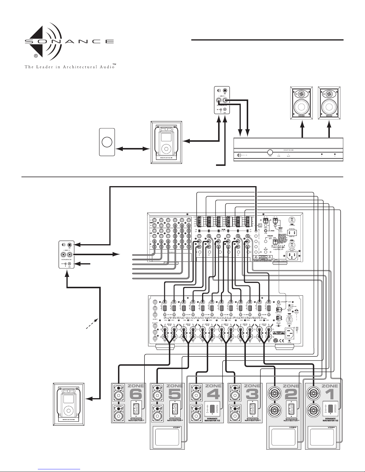
IR CONTROL IN AN iPort SYSTEM
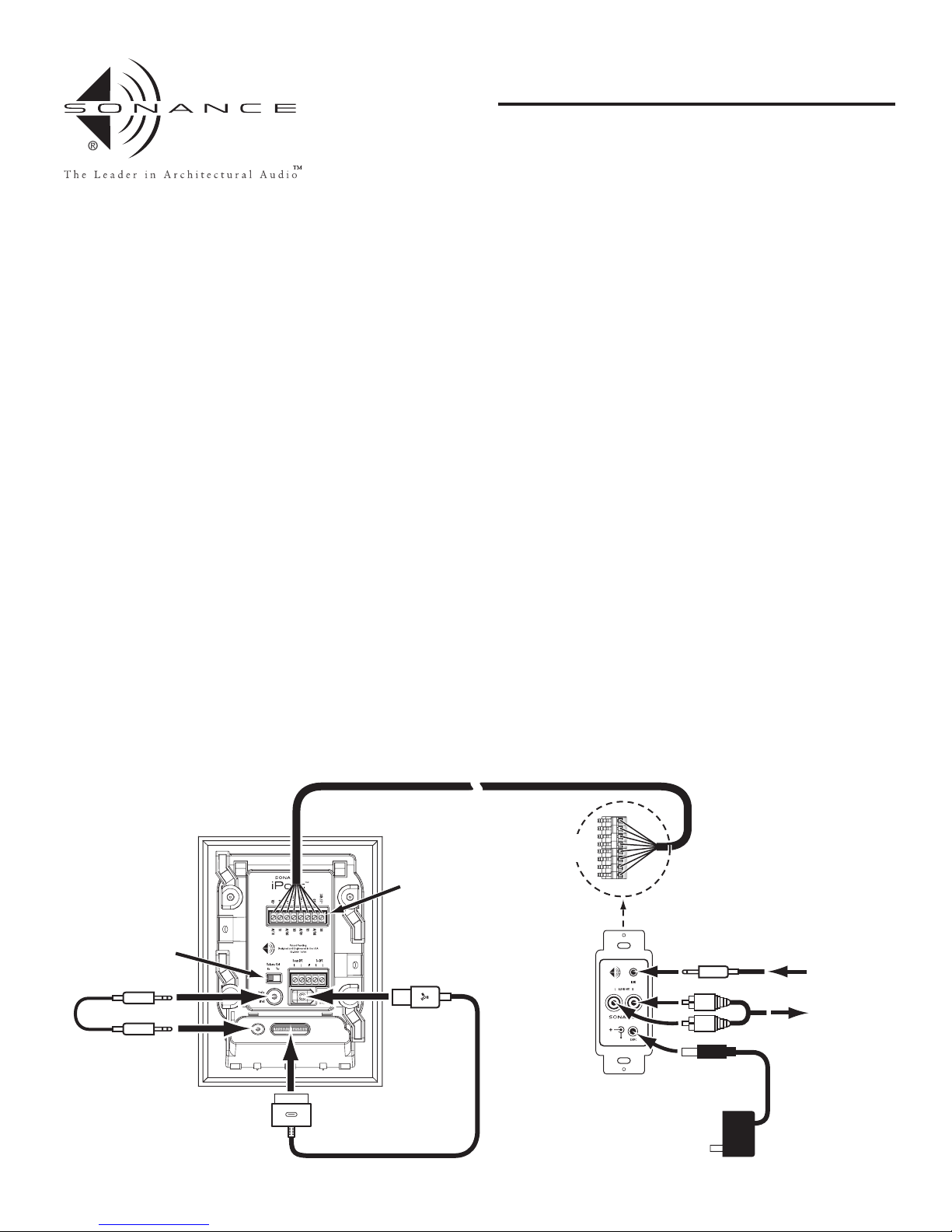
The iPort has built-in IR emitters that allow it to relay IR control signals
to the iPod from Sonance OptiLinQ products or distributed audio systems
like the DAB1 and Navigator Harbor. Through these systems, the iPort/iPod
can be controlled by the K2, K1, DAB1 and Navigator keypads. See Figure 6
for connections.
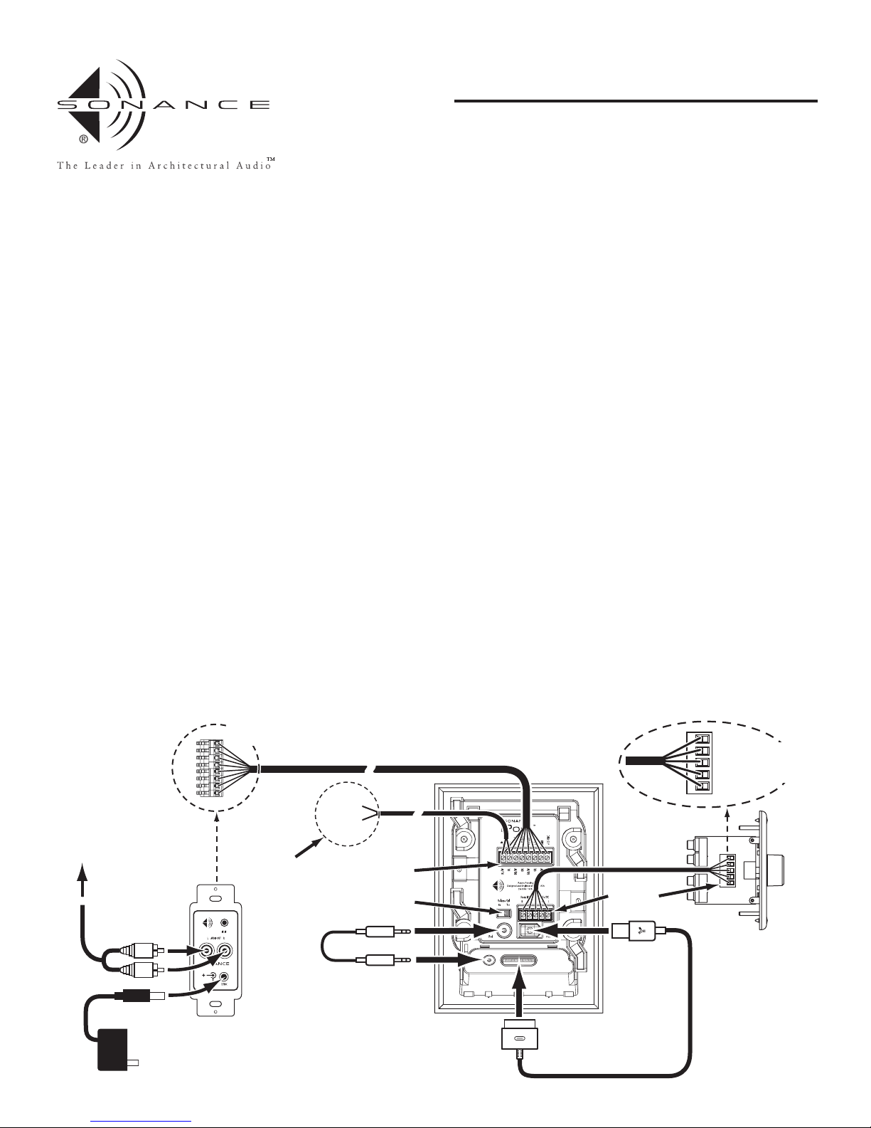
In local zone systems, IR signals from a local IR controller can be injected on
the iPort’s +IR (Data) and –IR (GND) connections. See Figure 5 for details.
iPort IR control codes for the K2, K1, DAB1 and Navigator keypads can be
downloaded for free at the Sonance website (www.sonance.com).
Important: The iPort requires the naviPOD IR receiver (not included) to control
the iPod via IR. The naviPOD IR receiver can be purchased online from the
Apple iStore, ClubMac.com or DrBott.com.
Note: The naviPOD must be connected to the iPod before the iPod is docked in
the iPort.
SPECIFICATIONS
Frequency Response: 20Hz – 20kHz (±0.25dB) @ 500 ft. CAT-5
THD+Noise: < 0.015%, 20Hz – 20kHz @ 500 ft. CAT-5
Signal to Noise: > 90dB (A wtd.) @ 500 ft. CAT-5
Maximum signal input: 1.5V RMS
Power supply: 15V DC, 500mA, regulated
TECHNICAL ASSISTANCE AND SERVICE
If you any have questions about the operation or installation of this product,
please call our Technical Assistance Department on any business day at
(800) 582-0772 or (949) 492-7777; from 7 a.m. to 5 p.m., PST.
If your Sonance OptiLinQ IR Learner should need repair or service, contact
your Sonance Authorized Dealer for help, or use the following procedure:
1. Prior to calling, note the product’s model number, serial number, pur-
chase date, and the name and address of the dealer where you purchased
the product.
2. Contact our Technical Assistance Department at the above number(s)
and describe the problem the unit is experiencing. If applicable, they
will issue a Return Authorization Number.
IMPORTANT: YOU MUST HAVE PRIOR AUTHORIZATION TO
RETURN YOUR OPTILINQ IR LEARNER TO SONANCE!
3. If you’re directed to return the unit to Sonance for repair, pack the unit
in its original shipping carton. If needed, you can obtain replacement
packaging from us for a small charge. Note: it is best if you place the box
into an additional outer “overcarton” before shipment to minimize a
chance of theft in shipment. Please include a copy of the original bill of
sale inside the package.
4. Contact United Parcel Service, Federal Express, or RPS to arrange pre-
paid (not collect) shipping. Do not use the U.S. Mail Service.
IMPORTANT: FREIGHT COLLECT SHIPMENTS WILL BE
REFUSED.
55..WWrriitteetthheeRReettuurrnnAAuutthhoorriizzaattiioonnNNuummbbeerroonntthheeoouuttssiiddeeoofftthheesshhiippppiinnggccaarrttoonn..
6. Ship the packaged unit to:
Quality Assurance Department
Sonance
212 Avenida Fabricante
San Clemente, CA 92672-7531
WARRANTY COVERAGE (U.S. ONLY)
If, within five (5) years from the date shown on the bill of sale, the unit
fails, due to a defect in workmanship or material, Sonance will, at its
option and at no charge, repair or replace the components of such unit
which prove to be defective. For this warranty to be effective, the bill of
sale must show that the unit was purchased from an "Authorized Sonance
Dealer" and must list the price paid. This warranty shall apply exclusively
to the original purchaser and shall not apply to units purchased for indus-
trial or commercial use.
Furthermore, this warranty shall not apply if:
1) Damage to the unit was caused by accident, abuse, or misuse;
2) The unit was opened, modified, or repaired by unauthorized per-
sonnel; or
3) The unit was not used as outlined in the operating instructions.
EXCLUSIONS AND LIMITATIONS
The warranty set forth above is in lieu of all other warranties, express or
implied, of merchantability, fitness for a particular purpose, or otherwise.
The warranty is limited to Sonance products registered herein and specif-
ically excludes any damage to loudspeakers and other allied or associated
equipment which may result for any reason from use with this product.
Sonance shall, in no event, be liable for incidental or consequential dam-
ages arising from any breach of this warranty or otherwise. This warranty
gives you specific legal rights, and you may have other rights which vary
from state to state.
7
INSTRUCTION MANUAL
SONANCE iPort™
IN-WALL DOCKING SYSTEM

8
Sonance • 212 Avenida Fabricante • San Clemente, CA 92672-7531, USA • (800) 582-7777 or (949) 492-7777 • FAX: (949) 361-5151 • Technical Support: (800) 582-0772
www.sonance.com 33-3504 11/04
©2004 Sonance. All rights reserved.
Sonance, Sonance iPort, OptiLinQ and RotoLock are trademarks of Sonance. Apple and iPod are trademarks of Apple Computer, Inc. naviPOD is a trademark of Ten Ventures, Inc.
All specifications are subject to change without notice.
Table of contents
Other Sonance Docking Station manuals