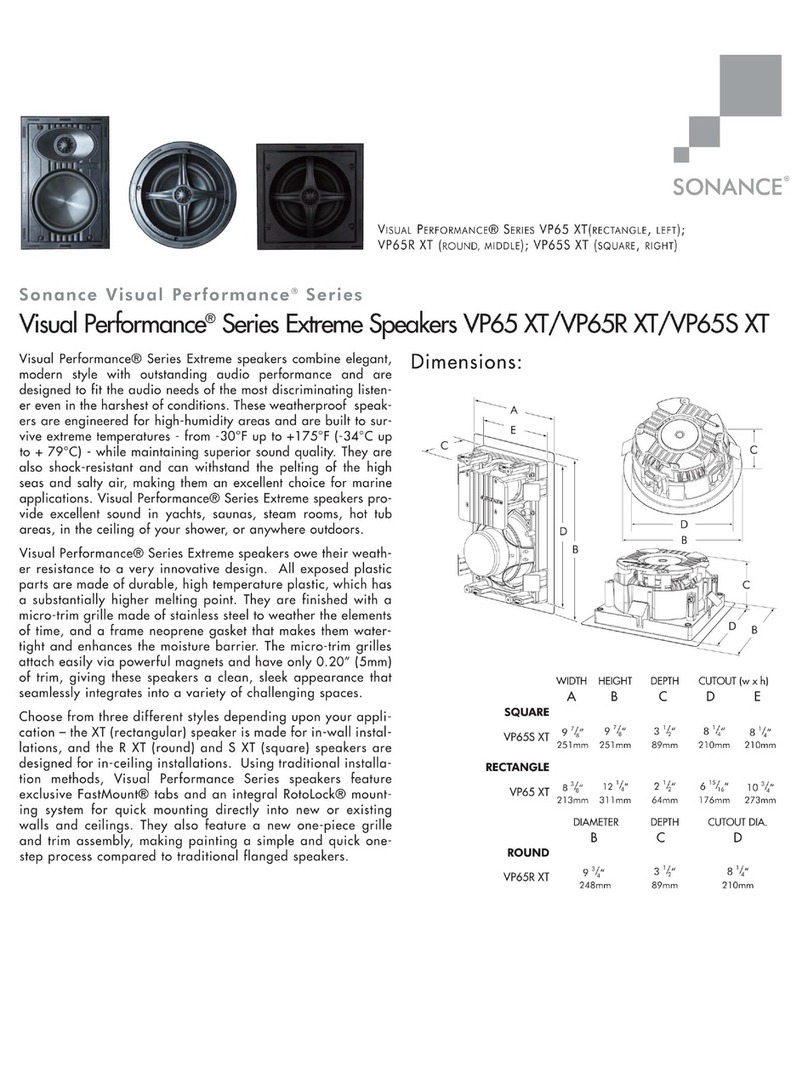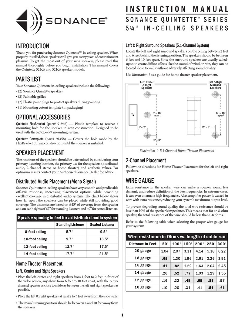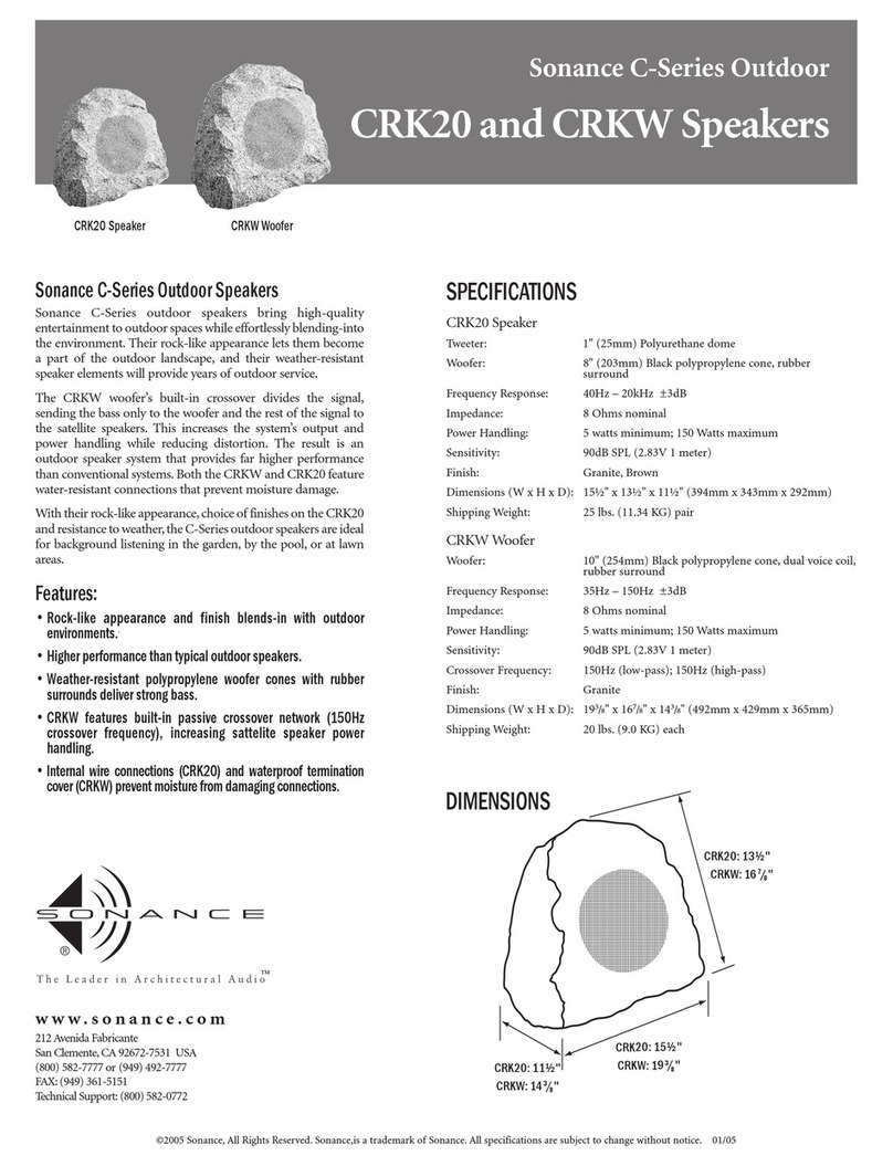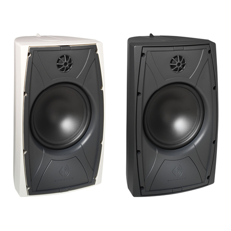
Figure 4: Tightening the RotoLock
Screws
Figure 6: Subwoofer Connection
Figure 5: Pivoting the MAG6R Woofer
Figure 3: Inserting the Speaker Into
the Mounting Hole
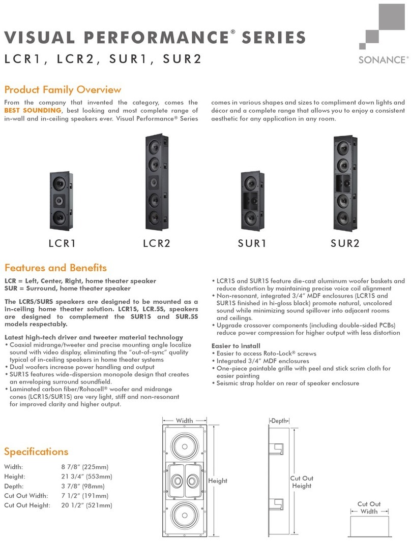
SUBWOOFER
OUTPUT
Surround Sound
Processor/Receiver
AUDIO CABLE
CAN ICES-3 (B)/NMB-3(B)
Roto-Lock
Clamps
(retracted)
Roto-Lock
Screws
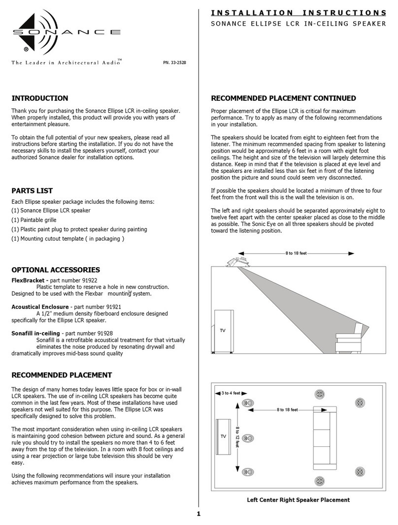
3. Make sure all the Roto-Lock toggle feet are retracted so
that they are tucked within the mounting hole’s border.
Insert the speaker into the hole in the ceiling (Figure 3:).
The Roto-Lock system can accommodate a ceiling material
thickness of 1-1/2” (38mm).
NOTE: ADJUST THE TENSION OF THE ROTO-LOCK CLAMPS
SO THAT THE SPEAKER FRAME IS FLAT. THIS WILL HELP
ENSURE THAT THE GRILLE CONTACTS THE CEILING ALL THE
WAY AROUND THE SPEAKER FOR A PROPER FIT.
6. The micro-trim grille is held in place by several small,
powerful magnets on the speaker frame. Place the grille
against the speaker and the magnets will hold it firmly in
place. When properly installed, the grille trim should make
contact with the wall all the way around the speaker.
SPEAKER ADJUSTMENTS
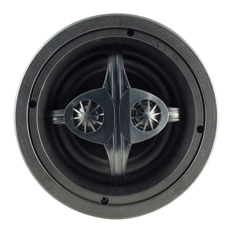
MAG6R SUR – Surround Channels
The woofer of the MAG6R
SUR should be pivoted
towards a wall or window,
away from the listeners
to create a more spacious
surround presentation.
To pivot the woofer apply
light pressure to the ring
around the outside edge
of the woofer, as shown in
(Figure 5:). Take care not
to touch or apply pressure
to the cone itself.
MS10 SUB - CONNECTION
Your MS10 SUB will need both AC power and a standard
subwoofer cable with RCA connectors on both ends unless
using the provided Wireless Transmitter/Receiver. For help
setting up the Wireless Transmitter/Receiver please see
instruction sheet provided in Transmitter/Receiver box.
Follow the connection example in (Figure 6:) below for
connecting the MS10 SUB directly to your A/V home theater
receiver. You’re A/V home theater receiver should have a LFE
or SUB OUT connector, the cable from your MS10 SUB should
be connected here.
MS10 SUB - CROSSOVER CONTROL
The crossover control on the rear panel of the MS10 SUB
(Figure 7:) should normally be set to the 250Hz or FULL
CLOCKWISE setting.
A/V home theater receivers have built in crossover filters
for subwoofer and satellite speakers. The settings for the
crossovers can be adjusted in the on screen menu for your
A/V home theater receiver. By setting the MS10 SUB in this
way the correct crossover filter will be applied in your A/V
home theater receiver and not in the subwoofer.
If you want to experiment with the crossover control on the
rear panel of the MS10 SUB the variable internal crossover
operates between 50Hz and 250Hz, with a crossover slope of
12dB/octave.
MS10 SUB - PHASE SWITCH
The phase switch on the rear panel of the MS10 SUB (Figure 7:)
should generally be left in the 0 DEG settings.
When the subwoofer’s PHASE switch is in the 0 position, a
positive input voltage will cause the woofer cone to move
out (towards the room). When the PHASE switch is in the 180
position, a positive input voltage will cause the woofer cone
to move in (away from the room).
There is no absolute correct setting for the PHASE switch.
Depending on the location of the subwoofer relative to your
main speakers and seating location, one of the settings will
produce a better match with the main speakers, improving
bass impact, and in some cases, improving overall bass level
as well.
To determine the correct setting of the PHASE switch, listen
to a movie or music with significant impactful bass content
with the switch in each position, it may be helpful to sit in the
normal listening position while someone else changes the
PHASE switch between 0 and 180. Leave the switch in the
position that produces audibly louder bass with more impact.
4
Figure 4: Tightening the RotoLock
Screws
Figure 6: Subwoofer Connection
Figure 5: Pivoting the MAG6R Woofer
Figure 3: Inserting the Speaker Into
the Mounting Hole
SUBWOOFER
OUTPUT
Surround Sound
Processor/Receiver
AUDIO CABLE
CAN ICES-3 (B)/NMB-3(B)
Figure 4: Tightening the RotoLock
Screws
Figure 6: Subwoofer Connection
Figure 5: Pivoting the MAG6R Woofer
Figure 3: Inserting the Speaker Into
the Mounting Hole
SUBWOOFER
OUTPUT
Surround Sound
Processor/Receiver
AUDIO CABLE
CAN ICES-3 (B)/NMB-3(B)
4. Tighten the screws on the front of the speaker bae.
The Roto-Lock toggle feet will automatically rotate into
position and begin clamping the speaker (Figure 4:).
When you notice resistance on the screws the speaker
has been clamped successfully.
5. I M P O R T A N T : Always use low torque settings;
NEVER over-tighten.
Roto-Lock
Clamps
(retracted)
Roto-Lock
Screws
LFE
SUBWOOFER
OUTPUT
Surround
Processor/Receiver
Sonance
Subwoofer
AUDIO CABLE
STATUS
LINE LEVEL INPUT
VOLUME
MIN MAX
CROSSOVER
50 HZ 250 HZ
150 HZ
75HZ 200 HZ
BYPASS
0 DEG 180 DEG
90 DEG
PHASE
RIGHTLEFT/LF E
GROUND LIFT
GROUNDED
ISOLATED
100 -120V 220– 24 0V
FUSE T4 AL / 250 VAC
AC 10 0-120V ~60Hz
AC 22 0-240V ~50Hz
ON
OFF
POWER
S/ N
MADE IN CHINA
This device complies with part15 of the FCC
Rules.
Operation is subject to the following two
conditions:
(1) This device may not cause harmful
interference.
(2) This device must accept any interference
received, including interference that may cause
undesiredoperation.
FCC COMPLIANCE NOTICE
CAUTION
RISKOF ELECTRIC SHOCK DO NOT OPEN
RISQUEDE CHOC ELECTRONIQUE NE PAS OUVRIR
AVIS
GMA-503573-EA
MS10SUB
MAG6R SUR Roto-Lock
Clamps (retracted)
MAG6R SUR
Roto-Lock Screws
MAG6 LCR
Roto-Lock
Clamps
(retracted)
MAG6 LCR
Roto-Lock
Screws
FIGURE 4: TIGHTENING THE ROTO-LOCK SCREWS
FIGURE 3: INSERTING THE SPEAKER INTO THE MOUNTING HOLE
FIGURE 6: MS10 SUB CONNECTION EXAMPLE
FIGURE 5: PIVOTING THE
MAG6R SUR WOOFER
