manuals.online logo
Brands
  1. Home
  2. •
  3. Brands
  4. •
  5. Sonance
  6. •
  7. Speakers
  8. •
  9. Sonance VIRTUOSO A800DR User manual

Sonance VIRTUOSO A800DR User manual

For best performance the Virtuoso A800DR woofer should be placed in
the front corner of the room as shown in the illustration below. Keep
the woofer as close as possible to the left, center and right speakers
to assure seamless integration of the sound from the main speaker
and the woofer.
The woofer should not be mounted in the same joist bay as the left
and right speakers.
PN. 33-2294
I N S T A L L A T I O N I N S T R U C T I O N S
SONANCE VIRTUOSO3A800DR IN-CEILING WOOFER
INTRODUCTION
Thank you for purchasing Sonance Virtuoso A800DR in-ceiling woofer.
When properly installed, this product will provide you with years of
entertainment pleasure.
To obtain the full potential of your new speaker, please read all
instructions before starting the installation. If you do not have the
necessary skills to install the speakers yourself, contact your
authorized Sonance dealer for installation options.
PARTS LIST
Each Virtuoso A800DR includes the following items:
(1) Sonance Virtuoso A800DR speaker
(1) Sonance Virtuoso A800 150 watt amplifier
(1) Paintable grille
(1) Plastic paint plug to protect speaker during painting
(1) Mounting cutout template ( in packaging )
1
HOME THEATER PLACEMENT
Home Theater Placement
2 - CHANNEL AUDIO PLACEMENT
In a two channel system the woofer should be located in a corner of
the room and as close as possible to the left or right speaker. Corner
placement of the woofer will provide more predictable performance
and higher output level.
Two Channel Audio Placement
TV
Virtuoso A800DR woofer
IMPORTANT SAFETY INSTRUCTIONS
When using your Virtuoso A800DR woofer, basic safety precautions should always be followed
to reduce the risk of fire, electric shock, and injury to persons, including the following:
1. Read and understand all instructions.
2. Retain the safety and installation instructions for future reference.
3. Follow all warnings and instructions in this manual and marked on the product.
4. Any service or repair required must be performed by qualified factory authorized
personnel.
5. Do not use this product in a high humidity environment or near water, for example a wet
basement, wet bar, or swimming pool.
6. Never touch the drivers or push objects of any kind into this product through the grilles.
7. Always provide adequate ventilation for the Virtuoso A800 amplifier. Allow a minimum
of one inch above and three inches behind the amplifier. Do not block cooling vents on
the amplifier case.
8. The amplifier should be situated away from heat sources such as heat registers,
radiators, stoves, or other appliances that produce heat.
9. The amplifier should only be connected to a power supply of the type marked on the
back panel. The power supply cord should be routed to avoid damage from contact with
sharp objects or being stepped on.
10. Unplug the amplifier during thunderstorms or when the system will be unused for
extended periods.
11. Exercise care to avoid spilling liquids on or in the amplifier or speakers.
12. Do not place the amplifier on an unstable table, stand, or cart.
Improper placement of the amplifier may cause it to fall on an
adult or child causing serious injury and damage to the amplifier.
13. The Virtuoso A800 amplifier shall not be exposed to dripping or splashing and that no
objects filled with liquids, such as vases, shall be placed on the Virtuoso A800 amplifier.
14. Cleaning - The appliance should be cleaned only as recommended by the manufacturer.
15. Non-Use Periods - The power cord of the appliance should be unplugged from the outlet
when left unused for a long period of time.
16. Damage requiring service - The appliance should be serviced by qualified service
personnel when:
A. The power supply cord or the plug has been damaged
B. Objects have fallen, or liquids have been spilled into the appliance
C. The appliance has been exposed to rain
D. The appliance does not appear to operate normally or exhibits a marked
change in performance
E. The appliance has been dropped or appears to have been damaged
17. Servicing - The user should not attempt to service the appliance beyond that described in
the installation instructions. All other servicing should be refereed to qualified service
personnel.
18. Storms - To prevent damage to components, unplug all electronic equipment during
thunderstorms.
CAUTION
RISK OF ELECTRIC SHOCK
DO NOT OPEN
CAUTION: TO REDUCE THE RISK OF ELECTRIC
SHOCK,DO NOT REMOVE COVER (OR
BACK)NO USER SERVICEABLE PARTS
INSIDEREFER SERVICING TO
QUALIFIEDSERVICE
PERSONNEL
The lighting flash with arrowhead symbol, within an
equilateral triangle, is intended to alert the user to the
presence of uninsulated dangerous voltage within the
product's enclosure that may be of sufficient magnitude
to constitute a risk of electric shock to persons.
The exclamation point within an equilateral triangle is
intended to alert the user to the presence of important
operating and maintenance (servicing) instructions in the
literature accompanying the appliance.
WARNING: TO PREVENT FIRE OR SHOCK
HAZARDDO NOT EXPOSE THIS APPLIANCE
TORAIN OR
MOISTURE
2
WIRE GAUGE AND QUALITY
PREPARING THE INSTALLATION LOCATION
Sonafill3
Insulating the ceiling cavity
Retrofit
The total wire resistance should be less than 10% of the speaker
impedance. If using an 8 ohm speaker, your total wire resistance
should be no more than 0.8 ohms.
In simple terms, the extra resistance from the wire will have a very
negative affect on the sound quality of the speaker. The sound can be
less dynamic, definition of bass frequencies can be reduced. Amplifier
power is also wasted in the wire, reducing the maximum output level
of the system.
Please refer to the following chart when deciding on the appropriate
wire gauge for your installation.
Wire resistance in Ohms vs. length of cable run
Distance in Feet 50' 100' 150' 200' 250' 300'
.86
.65
.43
.27
.17
.11
18 gauge
16 gauge
14 gauge
12 gauge
10 gauge
20 gauge 1.73
1.30
.85
.54
.34
.22
2.59
1.94
1.28
.81
.51
.33
3.45
2.59
1.71
1.08
.68
.44
4.32
3.24
2.14
1.35
.85
.56
5.18
3.89
2.56
1.62
1.02
.67
Speaker performance can be enhanced by insulating the cavity with
fiberglass insulation.
When installing speakers in a ceiling, it is best to lay a sheet of
unfaced fiberglass insulation over the back of the speaker.
To further improve the sound quality, install insulation in the bays
adjacent to the speaker location. This will reduce noise produced by
the unsupported drywall.
Sonafill is a retrofitable acoustical treatment for loudspeakers that
virtually eliminates the noise produced by resonating drywall and
dramatically improves bass sound quality. Sonafill also reduces room-
to-room noise especially in multi-channel installations where many
speakers are installed.
The Sonafill system consists of two pillows and four tiles. Installation
is accomplished by first adhering the tiles to the inside of the cavity,
then stuffing the two pillows in place behind the tiles.
The Sonafill System
All Sonance speakers are designed to be relatively insensitive to
changes in enclosure volume. To achieve the ultimate performance
from the Virtuoso A800DR speaker, a section of the ceiling bay can be
sectioned off to form a back box. Building this enclosure will create a
dramatic improvement in the quality of bass response and power
handling.
Back box volume requirement:
A800DR 1.50 cubic feet (45.5 liters)
New Construction
Virtuoso DR FlexBracket
The Virtuoso A800DR speaker features an integral Roto-Lock3
mounting system for quick mounting into ceilings. The Virtuoso DR
FlexBracket is only necessary in new construction installations when
reserving a location for the speaker is desired.
The FlexBracket will serve as a guide for the drywaller when cutting
holes for in-ceiling speakers. The FlexBracket is nailed or screwed to
the joists so that the hole is in the desired location once the drywall is
installed.
With the Roto-Lock system, the speaker can be installed directly into
existing ceilings. Once the hole is cut and the cable is run, the
speakers can be installed in a matter of seconds.
Once you have determined the area you would like to locate your
speakers, you will need to do an obstruction survey. Before you cut
the hole for the speaker, be certain no joist, conduit, pipe, heating
duct or air return will interfere with the speaker.
The Virtuoso A800DR speaker requires a hole that is 10" in diameter.
There must also be 5-3/4" of depth within the ceiling for the speaker.
A cut out template is provided in the packaging of the speaker.
Position the template where the speaker is to be located and pencil an
outline on the ceiling. If you are unsure about obstructions drill a small
hole in the center of the circle and insert a coat hanger into the hole
to feel for possible obstructions. If no obstructions are found, proceed
with cutting the hole using a drywall saw and run the speaker wires.
Acoustic Pillow
Acoustic Pillow
Damping Tiles
Damping Tiles
FlexBracket - part number 90-1358
Plastic template to reserve hole in new construction.
Designed to be used with the Roto-lock3mounting system.
Coverplate - part number 91457
Designed to cover hole made by FlexBracket3until the
speaker is installed.
OPTIONAL ACCESSORIES
This switch is set in the 120 volt position from the factory. This is the
correct setting for use in the United States.
If you are using this amplifier in a country where the voltage is
between 220 and 240 volts this switch should be changed to the 230
volt setting. If you are using the amplifier in its 230 volt setting the
fuse located above the power connector must be changed.
IMPORTANT:Included with the amplifier is a 2 amp fuse for this
purpose. Before making any changes to the voltage setting or the fuse
make sure the amplifier is unplugged from its power source.
3
INSTALLING THE SPEAKERS
Make sure the Roto-Lock clamps are in
the full clockwise position so that all the
clamps are tucked within the cutout
border. Insert the speaker into the hole
in the ceiling.
Note: The maximum clamp thickness is
1-1/4" (32mm)
Tighten the four screws on the front of
the baffle. The Roto-Lock clamps will
rotate into position automatically and
begin clamping. When you notice
resistance on the four screws, the
speaker has been clamped successfully.
The flange is designed to flex and
conform to any small imperfections in
the wall surface. The screws should not
be tightened so far that the flange bows
out.
Step 2
Step 3
Remove the paint plug from the
speaker. Attach the wire from your
amplifier to the terminals on the back of
the speaker. Double check the polarity
of the speaker wires, amplifier + to
speaker + and amplifier - to speaker -.
Proper polarity is critical in home
theater installations.
Step 1
After the speaker is clamped to the
drywall the grille can be installed. Insert
about half of the grille into the groove at
the edge of the speaker. Gently fit the
remaining half of the grill into the
speaker by working your hands around
the speaker fitting the grille into the
groove as you go along.
Note: The torque applied to the
mounting screws can be adjusted for
proper grille fit.
Step 4
Line level input
Voltage Switch
Speaker level input
There are two ways to get your audio signal into the Virtuoso A800DR
amplifier, line level and speaker level. Under no circumstances should
you try to use both at the same time. Turn off all equipment before
connecting your the Virtuoso A800DR amplifier to your system.
Power connection
The Virtuoso A800DR amplifier uses a 14 gauge EIA standard 120 volt
grounded power cable. Never attempt to operate the amplifier from
the accessory outlet of another component.
CONNECTING THE AMPLIFIER
SONANCE S/
N_____________
___
A DIVISION OF DANA INNOVA TIONS SAN CLEMENTE,
CA 92672
CAUTION :FOR CONTINUED PROTECTION AGAINST FIRE
HAZARD USE ONLY SAME TYPE AND RATING FUSE.
RISK OF ELECTRIC
SHOCK
DO NOT OPEN
CAUTION
SPEAKER LEVEL
LINE
INPUT
LINE
OUTPUT
SUBWOOFER OUTPUT
+
-
WARNING HAZARDOUS ENERGY,MAKE PROPER SPEAKER CONNECTIONS;SEE OWNERS
MANUAL BEFORE USING DISCONNECT SUPPLY CORD BEFORE CHANGING FUSE
ATTENTION: DEBRANCHER AVANT DE REMPLACER FUSIBLE
ATTENTION: VOIR LE CAHIER D' INSTRUCTION
ATTENTION: UTILISER UN FUSIBLE DE RECHANGE DE MEME TYPE
Virtuoso Amplifier
Auto on / off switch
Voltage switch
Power connection
Auto on / off switch
When this switch is in the on position the amplifier will turn on when it
senses a signal on either of the inputs. The amplifier will remain on for
approximately 5 minuets after a signal is detected. If you would like to
control the power of the amplifier, the switch should be set to the off
position. This will allow the amplifier to be turned on and shut off
using the power switch on the front of the chassis.
Woofer output
Line level inputs and outputs
Speaker level inputs and outputs
Woofer output
The five way binding posts is where the wire from your Virtuoso
woofer will connect to the amplifier. Make sure when connecting the
wire that the polarity is correct; positive to positive and negative to
negative.
Audio input options
If you are using a receiver as the source in your system this will be the
input you will probably use. When using this input connect the speaker
output from your receiver to the speaker level input of the Virtuoso
A800DR amplifier. Connect the wires from your left and right main
speakers to the speaker level output of the Virtuoso A800DR amplifier.
The Virtuoso A800DR amplifier features line level inputs and unfiltered
line outputs. Use this connection if your receiver or preamp has a line
level subwoofer output. If you are using your Virtuoso A800DR in a
system with a separate preamp and amplifier you can connect the
Virtuoso A800DR between the preamp and amplifier using the input
and output jacks. If your subwoofer output from your receiver or
preamp is mono you can use either the left or right input on the
Virtuoso A800DR amp.
TECHNICAL ASSISTANCE AND SERVICE
The Technical Assistance Department at Sonance is available at (800) 582-0772
or (949) 492-7777 to answer any questions concerning the operation and
installation of your speaker between the hours of 9:00 AM and 5:00 PM Pacific
time, Monday through Friday, except holidays.
In the event your unit should need repair or service, you may return the unit to
your authorized dealer or use the following guidelines:
1. Be prepared to state the model number and / or serial number, date of
purchase and dealer's name and address when calling.
2. Contact Sonance directly at (800) 582-0772 or (949) 492-7777 or at
www.sonance.com
3. If you are returning the product directly to Sonance, call us to obtain a
return authorization number before shipping. YOU MUST HAVE PRIOR
AUTHORIZATION TO RETURN YOUR UNIT.
4. The original packaging must be used. If the original packaging is unavailable
replacements can be obtained from Sonance for a small fee.
5. Ship the product via United Parcel Service, Federal Express, or RPS.
Please do not use the U.S. Mail service.
6. Write the return authorization number on the outside of the box.
7. Ship to:
Attn: Quality Assurance Department
Sonance
212 Avenida Fabricante
San Clemente, CA 92672-7531
8. FREIGHT COLLECT SHIPMENTS WILL BE REFUSED !
WARRANTY COVERAGE SPEAKER ( U.S. ONLY )
EXCLUSIONS AND LIMITATIONS
If, within five (5) years from the date shown on the bill of sale, the unit fails due
to a defect in workmanship or material, Sonance will, at its option and at no
charge, repair or replace the components of such unit which prove to be
defective. For this warranty to be effective, the bill of sale must show that the
unit was purchased from an "Authorized Sonance Dealer". This warranty shall
apply exclusively to the original purchaser and shall not apply to units purchased
for industrial or commercial use.
Furthermore, this warranty shall not apply if:
1. Damage to the unit was caused by accident, abuse or misuse;
2. The unit was opened, modified, or repaired by unauthorized personnel.
3. The unit was not used as outlined in the operating instructions.
The warranty set forth above is in lieu of all other warranties, expressed or
implied, of merchantability, fitness for a particular purpose, or otherwise. The
warranty is limited to Sonance products registered herein and specifically
excludes any damage to loudspeakers and other allied or associated equipment
which may result for any reason from use with this product. Sonance shall in no
event be liable for incidental or consequential damages arising from any breach
of this warranty or otherwise. This warranty gives you specific legal rights, and
you may have rights which vary from state to state.
Sonance $212 Avenida Fabricante $San Clemente, CA 92672-7531, USA $(800) 582-7777 or (949)492-7777 $FAX: (949) 361-5151 $ Technical Support: (800) 582-0772
2002 Sonance. Sonance Virtuoso, Roto-Lock, and Sonafill are trademarks of Sonance.
c
WARRANTY COVERAGE AMPLIFIER ( U.S. ONLY )
If, within one (1) year from the date shown on the bill of sale, the unit fails due
to a defect in workmanship or material, Sonance will, at its option and at no
charge, repair or replace the components of such unit which prove to be
defective. For this warranty to be effective, the bill of sale must show that the
unit was purchased from an "Authorized Sonance Dealer". This warranty shall
apply exclusively to the original purchaser and shall not apply to units purchased
for industrial or commercial use.
Furthermore, this warranty shall not apply if:
1. Damage to the unit was caused by accident, abuse or misuse;
2. The unit was opened, modified, or repaired by unauthorized personnel.
3. The unit was not used as outlined in the operating instructions.
PAINTING THE SPEAKERS AND GRILLES
Speakers and grilles can be painted before installation, which will
eliminate the "paint scar" if the speaker needs to be removed for
service. Speakers may also be painted after installation, but before the
grilles are attached. All speakers come from the factory fitted with a
plastic "paint plug." Use the paint plug to protect the drivers while the
flange is being painted with the ceiling.
Sonance suggests always painting the grilles separate from the
speaker. The grilles may be lightly sprayed with thin paint (5 parts
thinning agent to 1 part paint), but be careful not to plug the holes.
Too much paint will adversely affect the sound of the speaker.
Once the grilles and flange are painted and dry, remove the paint plug
from the flange and install the grilles.
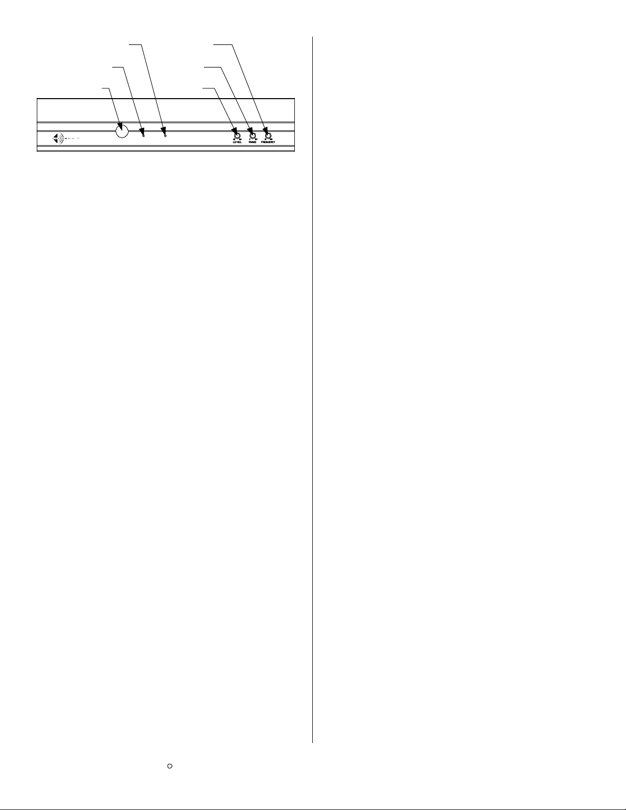
SETTING THE AMPLIFIER CONTROLS
PowerActivePower
The power switch turns the Virtuoso A800DR amplifier on and off. The
auto on switch on the back of the amplifier will affect the operation of
the power switch, see the description of the auto on/off control on
page three.
Power Switch
Active Light
Power Light
Frequency
Phase
Level
The active light shows when the amplifier is operating.
The power light indicates that the amplifier has electrical power
connected to it.
Use this control to adjust the frequency you would like the Virtuoso
woofer to extend up to. If you are using the woofer in a surround
system and the receiver or processor has a built in crossover you
should set the Virtuoso amplifier at 250hz.
The best way to adjust this control is to put on some music or pink
noise and adjust the control till the system sounds good to you.
The phase control can be adjusted from 0 to 180 degrees. A simple
explanation of this control would be that at the 0 setting when a
positive signal is sent to the woofer the woofer driver will move out.
When the control is set to 180 degrees a positive signal will make the
woofer driver move in. This control will allow you to better integrate
the Virtuoso woofer and your main speakers.
The best way to adjust this control is to put on some music or pink
noise and adjust the control till the system sounds good to you.
The level control adjusts the output level of the Virtuoso woofer. Use
the built in generator in your receiver or processor and a sound
pressure level meter to calibrate your system accurately. If your
equipment does not have a built in generator you can adjust the level
by ear. Listen to music you are familiar with and set the level to your
taste.
Voltage switch
Active light
Power light
Level
Phase
Frequency

Other Sonance Speakers manuals

Sonance CINEMA TWO SUB SYSTEM User manual

Sonance

Sonance CINEMA TWO SUB SYSTEM User manual

Sonance Symphony S623TR User manual

Sonance

Sonance Symphony S623TR User manual

Sonance Symphony Cabinet LCR Speaker User manual

Sonance

Sonance Symphony Cabinet LCR Speaker User manual

Sonance T-series User manual

Sonance

Sonance T-series User manual

Sonance 521 User manual

Sonance

Sonance 521 User manual

Sonance Visual Perfomance LCR1 User manual

Sonance

Sonance Visual Perfomance LCR1 User manual

Sonance MODERNO M6R SST SINGLE-STEREO TECHNOLOGY User manual

Sonance

Sonance MODERNO M6R SST SINGLE-STEREO TECHNOLOGY User manual

Sonance Visual Performance VP85 User manual

Sonance

Sonance Visual Performance VP85 User manual

Sonance Original Large Series User manual

Sonance

Sonance Original Large Series User manual

Sonance ThinLine TL622R User manual

Sonance

Sonance ThinLine TL622R User manual

Sonance SM55 User manual

Sonance

Sonance SM55 User manual

Sonance X4 Series User manual

Sonance

Sonance X4 Series User manual

Sonance CINEMA TWO SUB SYSTEM User manual

Sonance

Sonance CINEMA TWO SUB SYSTEM User manual

Sonance ORIGINAL Series User manual

Sonance

Sonance ORIGINAL Series User manual

Sonance Visual Performance VP45 User manual

Sonance

Sonance Visual Performance VP45 User manual

Sonance Symphony Extreme User manual

Sonance

Sonance Symphony Extreme User manual

Sonance Cinema Ultra II LCR User manual

Sonance

Sonance Cinema Ultra II LCR User manual

Sonance Visual Perfomance VP42 User manual

Sonance

Sonance Visual Perfomance VP42 User manual

Sonance VISUAL EXPERIENCE Series Installation instructions

Sonance

Sonance VISUAL EXPERIENCE Series Installation instructions

Sonance Visual Performance VP61 User manual

Sonance

Sonance Visual Performance VP61 User manual

Sonance Merlot 422MSQ User manual

Sonance

Sonance Merlot 422MSQ User manual

Sonance LS47SAT User manual

Sonance

Sonance LS47SAT User manual

Sonance PROFESSIONAL MKII Series User manual

Sonance

Sonance PROFESSIONAL MKII Series User manual

Sonance SB46 M User manual

Sonance

Sonance SB46 M User manual

Popular Speakers manuals by other brands

Vandersteen Audio VCC-5 Operation manual

Vandersteen Audio

Vandersteen Audio VCC-5 Operation manual

Power works MERCURY P8 user manual

Power works

Power works MERCURY P8 user manual

Definitive Technology Sound Cylinder user guide

Definitive Technology

Definitive Technology Sound Cylinder user guide

Goodmans GDTSPK02BLK user manual

Goodmans

Goodmans GDTSPK02BLK user manual

PYLE Audio PLATV65BT Installation instructions & owner's manual

PYLE Audio

PYLE Audio PLATV65BT Installation instructions & owner's manual

JL Audio PS-SWMCP installation instructions

JL Audio

JL Audio PS-SWMCP installation instructions

NHT SuperZero Xu user guide

NHT

NHT SuperZero Xu user guide

Lenoxx PR4350 instructions

Lenoxx

Lenoxx PR4350 instructions

Teufel Effekt 2 manual

Teufel

Teufel Effekt 2 manual

RS 20W Black RS Instruction leaflet

RS

RS 20W Black RS Instruction leaflet

Harman Harman/Kardon ONYX STUDIO 5 quick start guide

Harman

Harman Harman/Kardon ONYX STUDIO 5 quick start guide

Harbinger HA80 user manual

Harbinger

Harbinger HA80 user manual

Niles OS5.3Si Installation & operation guide

Niles

Niles OS5.3Si Installation & operation guide

Vexus Audio PSS302 user manual

Vexus Audio

Vexus Audio PSS302 user manual

Magnat Audio QUANTUM 508 TOWER owner's manual

Magnat Audio

Magnat Audio QUANTUM 508 TOWER owner's manual

Avante Achromic Series user manual

Avante

Avante Achromic Series user manual

Paso C420-EN Instructions for use

Paso

Paso C420-EN Instructions for use

Samsung HW-R47M Full manual

Samsung

Samsung HW-R47M Full manual

manuals.online logo
manuals.online logoBrands
  • About & Mission
  • Contact us
  • Privacy Policy
  • Terms and Conditions

Copyright 2025 Manuals.Online. All Rights Reserved.