SonarMed AirWave User manual
Operator’s Manual
August 2019 Edition
The foundation of airway management has just changed…
at the speed of sound.
AirWave System Operator’s Manual
i
Caution: US federal law restricts this device to sale by or on the
order of a physician.
You must read and understand these instructions in their
entirety prior to using the SonarMed AirWave System.
Because improvements to this manual and the products it describes will occur, please check that you are using
the most current version of this document by visiting www.sonarmed.com.
SonarMed, Inc.
12220 N. Meridian Street, Suite 150
Carmel, Indiana 46032
USA
Phone: (855) 240-0553
Fax: (866) 853-3684
support@sonarmed.com
www.sonarmed.com
Obelis s.a.
Boulevard General Wahis 53
1030 Brussels, Belgium
+32 3 732 59 54
References to “SonarMed” in this manual shall imply SonarMed, Inc. “SonarMed” is a registered trademark, and
“AirWave” is a trademark of SonarMed, Inc.
SP0610_P

Table of Contents
AirWave System Operator’s Manual
ii
Table of Contents
A. System Description...........................................................................................................................................................1
B. Indications for Use............................................................................................................................................................2
1. Contraindications ..........................................................................................................................................................2
C. Warnings and Precautions................................................................................................................................................3
D. Principles of Operation......................................................................................................................................................4
E. Airwave Monitor Package Contents..................................................................................................................................7
F. Displays, Indicators, and Controls ....................................................................................................................................8
1. AirWave Monitor Controls –Front Panel.......................................................................................................................8
2. AirWave Connections –Right Side...............................................................................................................................9
3. AirWave Monitor Screens............................................................................................................................................10
4. AirWave Monitor Indicators and Icons.........................................................................................................................12
5. General Symbols......................................................................................................................................................... 14
6. Basic Navigation and Editing.......................................................................................................................................15
G. AirWave System Operation............................................................................................................................................. 15
1. Powering On the AirWave Monitor..............................................................................................................................16
2. Start-Up Screens......................................................................................................................................................... 16
3. Main Menu Selections.................................................................................................................................................17
a. Alarm Settings ........................................................................................................................................................ 18
b. Set Carina Distance................................................................................................................................................19
c. Sound Speed Correction......................................................................................................................................... 20
d. Monitor AirWave Microphones................................................................................................................................ 23
e. Modify ETT Length ................................................................................................................................................. 24
f. ETT Movement Smoothing.....................................................................................................................................24
g. Patient Info.............................................................................................................................................................. 25
h. Data Logging ..........................................................................................................................................................25
i. System Settings...................................................................................................................................................... 25
4. Connecting an AirWave Sensor to an ETT.................................................................................................................. 25
5. Connecting the AirWave Sensor to the Monitor ..........................................................................................................27
6. Sensor Calibration....................................................................................................................................................... 28
7. Intubation with the AirWave Sensor Connected to an ETT .........................................................................................32
8. Connecting the AirWave Sensor to an Intubated ETT................................................................................................. 32
9. Modifying the Calibrated ETT Length.......................................................................................................................... 33
10. Patient Monitoring –Home Screen.........................................................................................................................36
11. Transitioning to Patient Monitoring After Set-Up.....................................................................................................38
a. Pre-Intubation.........................................................................................................................................................38
b. Using the Device to Aid in Intubation......................................................................................................................38
c. Ready to Set Baseline ............................................................................................................................................40
d. Baseline Set............................................................................................................................................................ 40
e. Set Carina Distance................................................................................................................................................41
12. Patient Monitoring - Waveform Screen...................................................................................................................41

Table of Contents
AirWave System Operator’s Manual
iii
13. Powering Off the Monitor........................................................................................................................................ 43
H. Cleaning, Maintenance and Disposal .............................................................................................................................44
I. Troubleshooting..............................................................................................................................................................45
1. Error Messages........................................................................................................................................................... 45
2. AirWave Sensor Health Metric.................................................................................................................................... 47
3. Sensor Suctioning....................................................................................................................................................... 47
4. ETT Movement Smoothing..........................................................................................................................................48
J. Service, Support, and Warranty...................................................................................................................................... 49
K. Parts and Accessories.................................................................................................................................................... 50
L. Specifications..................................................................................................................................................................51
1. AirWave Monitor.......................................................................................................................................................... 51
2. AirWave Sensor..........................................................................................................................................................51
3. System Accuracy ........................................................................................................................................................ 52
4. Storage & Operating Conditions.................................................................................................................................. 52
5. Electromagnetic Compatibility..................................................................................................................................... 53
Section A–System Description
AirWave System Operator’s Manual
1
A. System Description
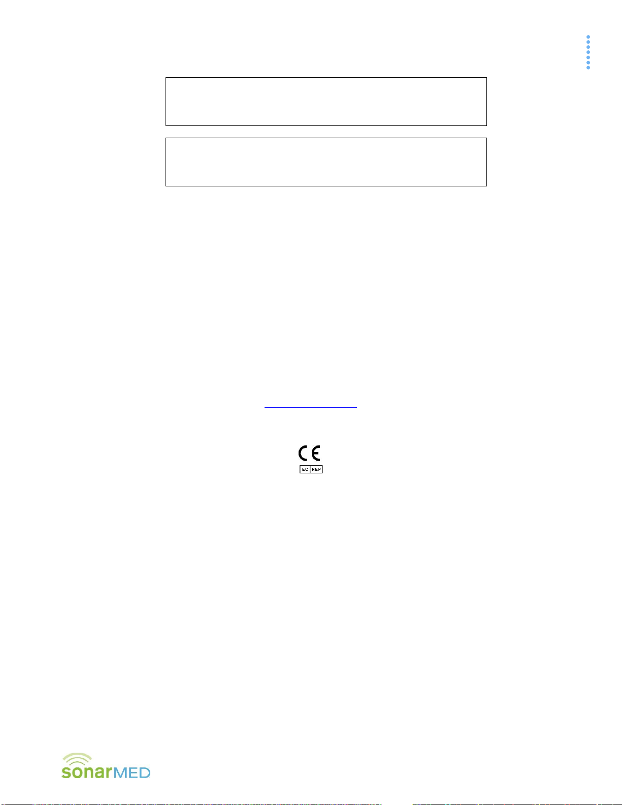
The SonarMed AirWave acoustic airway monitoring system consists of an AirWave Monitor, (Monitor) which is
used in conjunction with a single-use AirWave Sensor (Sensor) and a reusable cable (see Figure A-1).
Figure A-1
The Monitor contains signal-generating and echo-processing circuitry that uses proprietary software to monitor
the position and patency of an endotracheal tube (ETT) via the AirWave Sensor. The Monitor is powered from an
external power supply and has a battery backup that will allow the device to function for approximately 120
minutes without external power. The Monitor has a color display, which is used to present information about the
ETT status. This information can be used in an adjunctive manner to assist with management of the patient’s
artificial airway.
In order to attach the Sensor to the ETT, the standard 15-mm connector (also known as the “hub”) is removed
and replaced with the AirWave Sensor (see Figure A-2).
Figure A-2
AirWave Sensors
Cable
AirWave Monitor
Standard
Connector (Hub)
AirWave Sensor
ETT

Section B–Indications for Use
AirWave System Operator’s Manual
2
B. Indications for Use
The SonarMed AirWave is used to assist in verifying placement of the ETT, to assist in detecting movement of the
ETT tip, and to assist in detecting obstruction of the ETT and assist with listening to breath sounds.
The SonarMed AirWave is intended for use by qualified personnel to assist with artificial airway management for
patients in an in-hospital setting (intensive care, operating room, and emergency department settings, as well as
intra-hospital transport).
The SonarMed AirWave is to be used as an adjunct to normal clinical practice, and is not to be used as a stand-
alone diagnostic system.
The AirWave can be used for patients intubated with a 2.5 mm ETT up to a 9.0 mm ETT.
1. Contraindications
Do not use the AirWave Monitor or leave the AirWave Sensor connected to the ETT in an MRI environment.
For ETT ID sizes between 4.0 mm and 9.0 mm, do not use on a cuffless ETT. The AirWave is intended for
use only with a cuffed ETT for this size range.
Do not use on patients who require an ETT smaller than 2.5 mm ID.
Do not use the AirWave on patients ventilated with Heliox.
Do not use in a setting other than in-hospital.
Do not attempt to re-use or sterilize the AirWave Sensor; infection or cross-contamination is possible.
Sterilizing the Sensor may cause damage to the internal components, which can cause the SonarMed
AirWave to produce erroneous results.

Section C–Warnings and Precautions
AirWave System Operator’s Manual
3
C. Warnings and Precautions
The SonarMed AirWave Monitoring System (Monitor and Sensor) is not to be used as a diagnostic
tool; it is to be used as an adjunct to airway management only.
The SonarMed AirWave is to be used by properly trained personnel only.
Do not use an AirWave Sensor if its pouch is open or damaged.
Do not use the AirWave Monitor if it is damaged.
The AirWave Monitor is rated IPX1 for water ingress protection, which means the Monitor is resistant
to water dripping vertically onto the device. Other types of water exposure (e.g. sprays, submersion)
should be avoided.
Only the SonarMed AC-DC power supply may be used with the SonarMed Monitor. Use of another
power supply may put the patient at risk of an electrical hazard. Warning: To avoid the risk of electric
shock, this equipment must only be connected to a supply mains with protective earth.
When the Alarm Silence button is pressed, the Monitor speaker is disabled for two (2) minutes even if
a new alarm should occur during that period.
Some AirWave alarms may be manually disabled by the user. The Monitor will display the message
“An Alarm is Off” when this is the case. All alarms that have been disabled are reactivated to their
previous settings if the Monitor is powered off and back on.
Only upgrade firmware when the AirWave system is off the patient.
Presence of high oxygen levels (O2> 40%) or anesthesia gases affects the speed of sound. For best
results, it is important to modify the settings as described in Section G.c.
When using the SonarMed AirWave device in conjunction with a high frequency oscillatory ventilator
(HFOV), the manufacturer’s safety information and recommendations should be followed.
Only connect an ETT to an AirWave Sensor nozzle specified for that ETT ID. Failure to do so may
result in an unsecure fit between the Sensor and ETT and/or may cause the AirWave to provide
erroneous results.
The AirWave Sensor cable must be routed and secured in a way that prevents accidental disturbance
by the user, patient, or other persons.
If attaching the AirWave Sensor to an already intubated patient, care must be taken not to dislodge
the ETT while removing the standard ETT adapter and attaching the AirWave Sensor.
While using the AirWave’s feature for directly listening to the signals from the Sensor microphones,
system monitoring of ETT is discontinued until the system is returned to the patient monitoring
screen. This feature is used to both troubleshoot and listen to the patient’s breath sounds.
Improper cleaning methods or materials may damage the AirWave Monitor.
This device is a precision electronic instrument and must be repaired by qualified technical
professionals. Field repair of the device is not possible. Do not attempt to open the case or repair the
electronics. Opening the case may damage the device and voids the warranty.
Section D–Principles of Operation
AirWave System Operator’s Manual
4
D. Principles of Operation
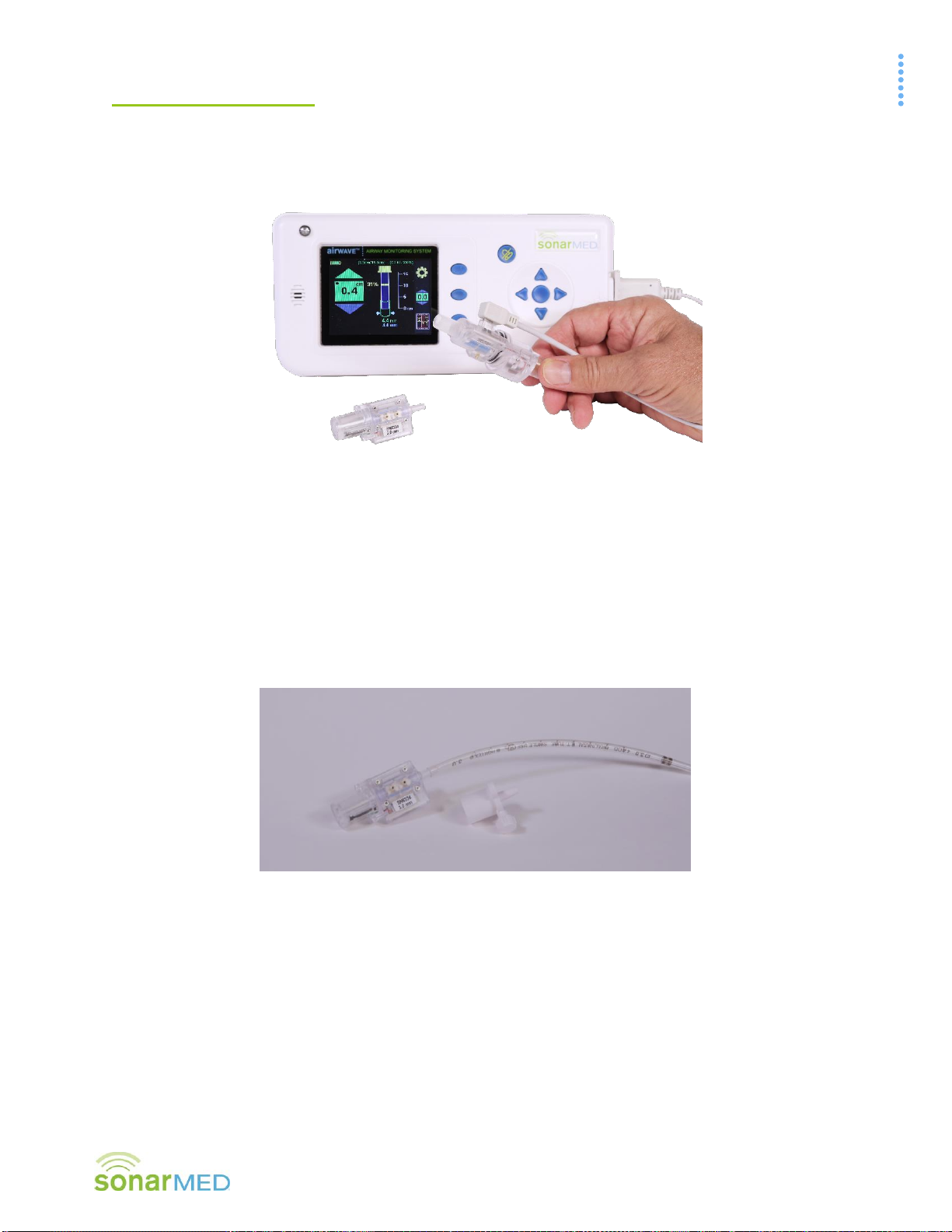
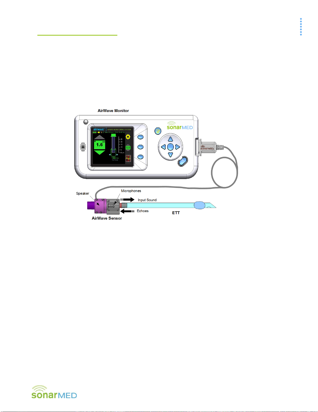
The AirWave System
The SonarMed AirWave Monitoring System, as shown in Figure D-1, consists of an AirWave Sensor connected to
the proximal end of an ETT, and a Monitor to which the Sensor is connected via a cable.
Inside the AirWave Sensor are embedded a miniature speaker, for emitting sound waves into the ETT, and
microphones, for sensing the returning acoustic echoes. The amplitudes and timing of the echoes are analyzed
by the Monitor to provide the following information:
•location and size of ETT obstructions
•size of the passageway around the ETT tip
•relative movements of the ETT tip within the trachea
Figure D-1
SonarMed AirWave System
During use of the AirWave, an option is provided via the Patient Monitoring Waveform Screen to view the echo
signal to provide a means to the user to verify that the signal is free of artifact and that the algorithm is properly
identifying and tracking the ETT and the patient’s airway echoes. This primer is intended to help the user to
better understand and interpret the AirWave echo signals.
Acoustic Reflectometry
The SonarMed AirWave employs the technique of acoustic reflectometry which consists of emitting acoustic
waves into an unknown object (or in this case, an intubated ETT), detecting the returning acoustic reflections
(echoes), and examining their timing and amplitudes to infer characteristics of the object in question.
As mentioned above, the AirWave Sensor contains a speaker, for generating acoustic waves which travel into the
ETT and airways, and two microphones (separated by a small distance), for converting the reflected waves into
an echo signal which is input into the Monitor’s proprietary algorithms. This echo signal consists of positive and
negative deflections that represent positive and negative sound pressure waves, respectively.
The use of two microphones to sense the acoustic waves allows the system to determine the direction from which
echoes arrive. As a result, the system can selectively filter all echoes that arise from devices on the ventilator
side of the Sensor, such as closed-circuit suction catheters, y-connectors, ETCO2sensors, filters, etc. This
selective filtering is critical for obtaining a clean echo waveform from the ETT and airways that is free of ventilator
circuit echoes.
Section D–Principles of Operation
AirWave System Operator’s Manual
5
Origin of Echoes inside Tubes
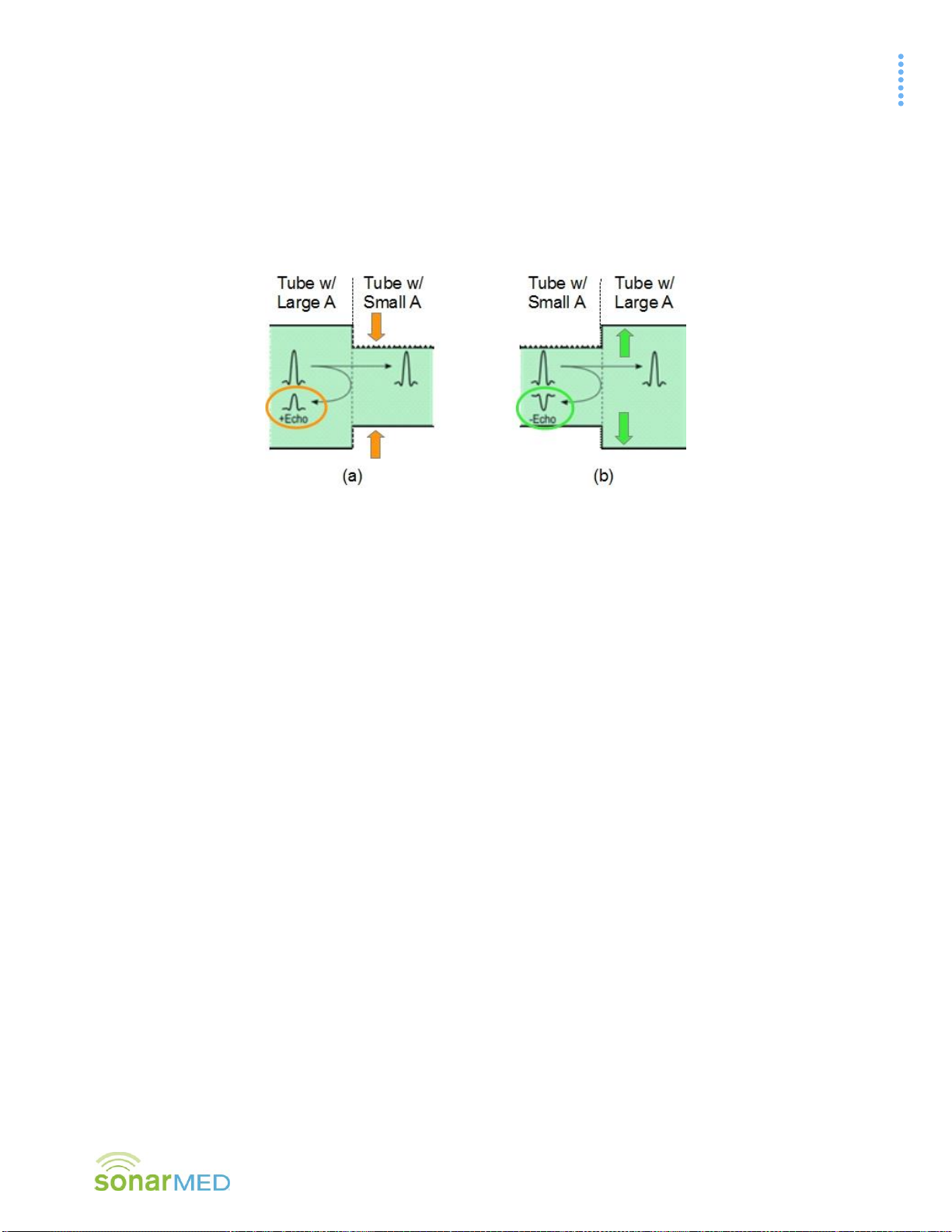
A key property of an acoustic wave propagating in a tube is that a fraction of the wave’s energy will undergo a
reflection each time it encounters a change in cross-sectional area (A). If the changing A is from larger to smaller
(as depicted in (a) in Figure D-2), a positive pressure wave is reflected (showing up as a positive deflection in the
echo signal). Conversely, if the changing A is from smaller to larger (see (b) in Figure D-2 below), a negative
pressure wave is reflected (showing up as a negative deflection in the echo signal). The delay time of each echo
identifies the distance of the changing A that caused the echo. The amplitude of each echo identifies
approximately how much the corresponding A changed.
Figure D-2
Reflection or echo signals that arise from a tube with (a) changing A from large to small and (b) changing A from small to large.
Echoes in the ETT and Airways
The human airways consist of a network of bifurcating branches that start at the trachea and terminate at the
alveoli (small sacs where oxygen-carbon dioxide exchange takes place). An interesting property of the airways is
that even though the A of each individual segment decreases as the branching depth increases, the total A
(adding As of all parallel segments) undergoes a rapid increase after several generations of airway branching.
Considering this morphology, the airways behave acoustically like a horn with a bell at the end. Therefore,
acoustic waves traveling down the airways, or the analogous horn model, will be reflected at the rapid increase in
total A. The negative pressure wave from this bell-shaped region is used as a reference to which changes in ETT
tip position are tracked. The bell begins around the 6th branching generation which is approximately 5 cm past
the carina in adults and about 2-3 cm past the carina in neonates. It is worth noting that there are no echoes of
significance that arise from the carina, since the additive A of the two mainstem bronchi is approximately equal to
the trachea A.
To illustrate the relationships between cross-sectional area, amplitude, and time delay, refer to Figure D-3
depicting an intubated ETT with a corresponding echo signal (pressure amplitude on y-axis and time delay on x-
axis). For each deflection in the echo signal, an arrow denotes the corresponding region in the ETT and airways
from which that echo arises.

Section D–Principles of Operation
AirWave System Operator’s Manual
6
Figure D-3
Relationship of AirWave Sensor and intubated ETT (top) to the corresponding echo signal recorded by the AirWave system
(bottom).
Description of Echoes
In Figure D-3, the first (leftmost) echo (1) is a positive deflection (positive pressure) which indicates an A change
within the Sensor ETT connector from larger to smaller. This corresponds to the diameter change within the
connector (for example, from 3.5 to 3.0 mm ID in the 3.0-mm Sensor).
The second echo (2) is a positive deflection immediately followed by a negative deflection which indicates an A
change from larger to smaller and then back to larger. This echo could be from a small obstruction within the
ETT, a kink in the ETT, or a patient biting on the ETT. If the echo amplitude were larger, this would correspond to
a larger obstruction. The AirWave system estimates the obstruction size from the echo amplitude and the
obstruction location from the echo delay time.
The third echo (3) is a negative deflection which indicates an A change from smaller to larger. This echo, referred
to as the ETT tip echo, is analyzed by the AirWave system to estimate the passageway size (effective diameter)
around the ETT. A negative deflection echo indicates that the ETT is located within a passageway that has a
larger A compared to the ETT (this would be the case for an ETT in the trachea). If this echo were to change to a
positive deflection, then this would indicate that the ETT is located within a passageway that has a smaller A
compared to the ETT. This may correspond to an ETT that is in the esophagus or bronchus, or that is clogged at
the tip, such as from mucus.
The last echo (4), referred to as the airway echo, arises from the aforementioned bell-shaped region in the
airways. The AirWave system tracks the time delay of the airway echo to estimate relative changes in the
distance between the ETT tip and the airway echo region. For example, if the time delay between the ETT tip
echo and the airway echo is decreasing (airway echo moves to the left), then this indicates that the ETT tip is
getting closer to the airway echo region, or that the ETT is migrating down the trachea.

Section D–Principles of Operation
AirWave System Operator’s Manual
7
All Lungs Are Not the Same
Accurate tracking of the airway echo by the system assumes that the echo shape remains consistent over the
duration of patient monitoring. Significant changes in the echo shape may result in the system reporting a change
in ETT position when the actual position has not changed. It is possible that the airway echo shape may change
due to airway changes that affect the geometry of the airway echo region. Some examples of airway changes
that may affect the airway echo shape include mucus plugs in a bronchus, or a significant change in middle
airway A due to bronchoconstriction or dilation. Therefore, when the system indicates ETT movement, it is
recommended that the user enter the Patient Monitoring Waveform Screen to compare the baseline echo
(indicated in light blue) and present airway echoes (indicated in yellow) to confirm the current echo has shifted in
time (moved left/right compared to the baseline echo) and that the baseline and current airway echoes have
similar shapes.
AirWave Sounds are Audible
While a majority of medical devices that employ acoustics do so in the ultrasonic frequency range, the AirWave
operates in the audible range below 8 kHz due to reasons related to the frequencies at which the ETT and
airways behave as waveguides. Operating in these frequencies creates a challenge for collecting echo signals
that are not corrupted by the sounds typically found within a ventilator circuit, such as respiratory sounds,
secretion sounds, cuff leak sounds, etc. As a result, the AirWave system uses a variety of data collection
strategies to collect a clean echo signal during ventilation. When connected to a patient, the system collects a
majority of its measurements during the quiet period of ventilation between end-expiration and inspiration.
Therefore, the AirWave Monitor provides updates to the ETT status approximately every patient breath depending
on the level of noise present between breaths. For cases where excessive noise interferes with acoustical
measurements such that the ETT status is not updating, it is recommended that the user enter the Listen to
AirWave Microphones Screen to listen directly to the Sensor microphones via the Monitor speaker. This assists
the user in determining the noise source so they can rectify it if possible. Examples of noise sources may include:
a leaky ETT cuff, secretions in the airway and/or ETT, a high respiratory rate, a nebulizer, and patient coughing.
E. Airwave Monitor Package Contents
(1) AirWave Monitor
(1) Carrying strap
(1) AC-DC Power Supply
(1) Hospital Grade Power Cord
(1) Sensor Cable
(1) Firmware Upgrade & Data Cable (RS232 Connection with USB-to-RS232 Converter Cable)
(1) Software and Documentation CD

Section F –Displays, Indicators, and Controls
AirWave System Operator’s Manual
8
F. Displays, Indicators, and Controls
This section describes the displays, indicators, and controls for the SonarMed AirWave Monitor.
1. AirWave Monitor Controls –Front Panel
Figure F-1
Table F-1
Control
Description
Alarm LED
This LED flashes red when an alarm condition is present. The LED flashes even if the audible
alarms are silenced
Display
Screen
The display screen of the AirWave Monitor is a color LCD.
Speaker
The speaker plays audible alarm tones when an alarm condition exists. The speaker is also
used to play the real-time signals sensed by the AirWave Sensor microphones.
Alarm Silence
Button
This button is used to temporarily silence audible alarms. Once pressed, the Monitor silences
alarm sounds for two minutes (including if a new alarm is triggered during that time). If an
alarm condition still exists after two minutes, the audible signal resumes.
Note: Pressing the Alarm Silence button a second time reactivates audible alarms.
Navigation
Arrows
The navigation arrows are used to move between user-selectable options on the screen and
to change user-editable values and parameters (right, left, up, down).
Enter Button
The center button is used to select items or lock in changes when editing a field.
Function
Buttons
The function buttons provide specific contextual functionality as indicated by the currently
displayed screen icons. Icons appear to the left of these buttons to indicate their current
function.
Power Button
Pressing the power button once turns on the AirWave Monitor. While the Monitor is on,
pressing and holding the power button for one (1) second turns the Monitor off, discontinuing
all monitoring functions. After turning the Monitor off, if it is plugged into the AC-DC power
supply and the battery is not fully charged, the Monitor screen powers back on with a
message that the battery is charging. The monitor can be turned off completely by pressing
the power button one more time.
Enter
Button
Alarm LED
Power Button
Display Screen
Alarm Silence Button
Navigation Arrows
3 Function
Buttons
Speaker

Section F –Displays, Indicators, and Controls
AirWave System Operator’s Manual
9
2. AirWave Connections –Right Side
Figure F-2
Table F-2
Port
Description
AC-DC Power
Port
This connector accepts the SonarMed AC-DC power supply.
Only the SonarMed AC-DC power supply may be used with the SonarMed Monitor. Use of
another power supply may put the patient at risk of an electrical hazard.
Note: To begin charging the battery, the Monitor must be connected to the AC power
source, and the Monitor must be turned on. Plugging in the AC power source to a Monitor
that is turned off will not charge the battery.
AirWave
Sensor Cable
Port
This connector accepts the SonarMed AirWave Sensor Cable.
Only connect the SonarMed AirWave Sensor Cable to this port.
Firmware
Upgrade and
Data
Communication
Port
This connector accepts the Firmware Upgrade Cable supplied with the SonarMed AirWave
Monitor which is used to upgrade system firmware.
Only upgrade the firmware when the AirWave system is not connected to a patient.
Only use the Firmware Upgrade Cable supplied by SonarMed.
AC-DC Power
Port Firmware Upgrade
and Data
Communication Port
AirWave Sensor Cable Port
Section F –Displays, Indicators, and Controls
AirWave System Operator’s Manual
10
3. AirWave Monitor Screens
This section provides a brief description of the screens that make up the user interface of the AirWave System.
Additional details, including more pictures, are included in subsequent sections.
System Start-up Screens (Sections G.2 - Start-Up Screens and G.6 - Sensor Calibration)
Figure F-3
These screens, beginning with the one shown in Figure F-3, appear when the unit is first powered on. If no
AirWave Sensor is connected to the Monitor, the system prompts to connect one. Once a Sensor is connected,
the user is guided through the calibration process to the Patient Monitoring Screen.
Patient Monitoring Screen (Section G.10 - Patient Monitoring –Home Screen)
This is the primary monitoring screen for the AirWave Monitor, also referred to as the Home Screen (see Figure
F-4). It provides icon-graphical and numerical representation of the status of the ETT including indicators for ETT
tip movement, passageway size, and tube obstruction.
Figure F-4

Section F –Displays, Indicators, and Controls
AirWave System Operator’s Manual
11
Waveform Screen (Section G.12 - Patient Monitoring - Waveform Screen)
This screen (see Figure F-5) provides an alternative visual representation of the information displayed on the
Patient Monitoring Screen in the form of the acoustic waveforms being analyzed by the AirWave.
Figure F-5
Settings Screens (Section G.3 - Main Menu Selections)
These screens are accessed through the Main Menu (see Figure F-6) by pressing the Gear Icon found on
most of the other AirWave screens and provide the interface for editing system parameters. These parameters
include alarm limits for ETT tip movement, passageway size, and obstruction, a patient identification number, an
ETT length setting, as well as settings for airway movement smoothing, data logging, and sound speed
correction.
Figure F-6

Section F –Displays, Indicators, and Controls
AirWave System Operator’s Manual
12
4. AirWave Monitor Indicators and Icons
Indicators (if applicable) are presented on all screens (see Figure F-7 and Table F-3).
Figure F-7
Table F-3
Indicator
Figure
Reference
Description
A
Battery Indicator –located in the upper left corner of the screen; the number
of bars indicates charge level, and the bars blink during charging.
B
External Power Indicator –when this symbol is present near the upper left
corner of the screen, the AirWave Monitor is being powered by the plugged
into AC-DC power supply.
C
Alarm Silence Indicator –when this symbol is present near the upper left
corner of the screen, the alarms on the AirWave Monitor have been muted
using the Alarm Silence button. The symbol begins to flash ten seconds prior
to the alarms becoming unmuted.
D
Uncalibrated Indicator –located in the upper center of the screen, this
indicates that a connected Sensor-ETT pair has not yet been calibrated for use
with the Monitor.
E
Calibrated Indicator –located in the upper center of the screen, this indicator
appears once a connected Sensor-ETT pair has been calibrated for use with
the Monitor. The left value is the ID of the ETT, the right value is the calibrated
length of the ETT.
F
Sound Speed Correction Indicator –located in the upper right corner of the
screen, this indicator shows the current user-selected setting that the AirWave
is using to compensate for changes in the speed of sound caused by high
oxygen concentrations (O2) or the presence of anesthesia gases.
G
Movement Smoothing Indicator –located in the upper left of the Patient
Monitoring Screen (below the battery indicator) and just above the Airway
Reflection Waveform on the Waveform Screen, this indicator shows that the
Movement Smoothing filter is active.
A
G
B
C
D/E
F
A
B
C
D/E
F
G
Section F –Displays, Indicators, and Controls
AirWave System Operator’s Manual
13
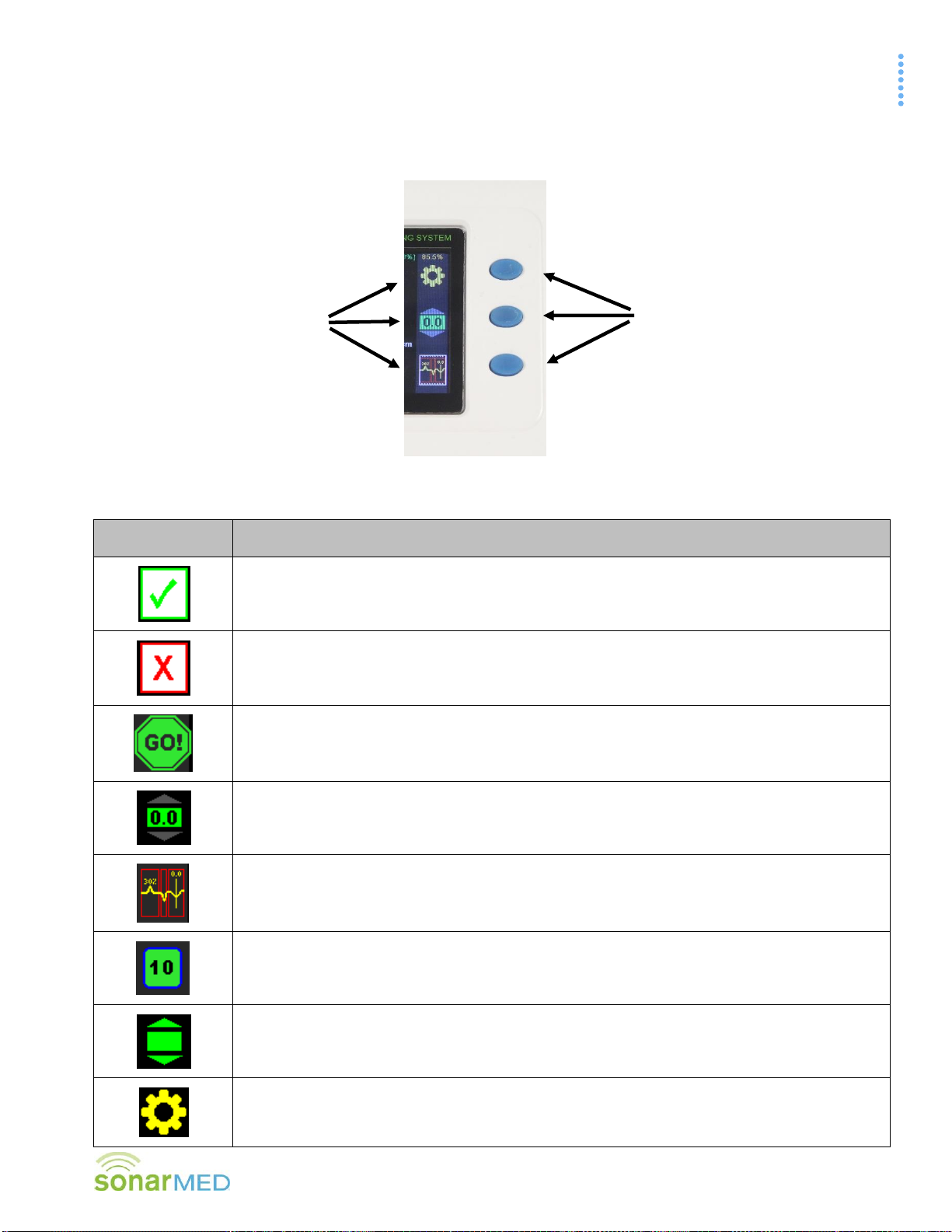
Icons appear next to the function keys to provide specific functionality depending on the current screen or action
being performed (see Figure F-8 and Table F-4).
Figure F-8
Table F-4
Button Icon
System Action When Pressed
Accept Changes / Yes Icon
Cancel Changes / No Icon
Monitoring Readiness Icon –Appears when the ETT is connected to the AirWave Sensor
and the Monitor detects what appears to be an intubated ETT. Press the button
corresponding to the icon to begin continuous monitoring of the ETT.
Set Baseline Icon –sets (or resets) the baseline (the current ETT tip location and
passageway size at the time the button is pressed) from which deviations in ETT tip position
and passageway size are measured
Waveform Screen Icon –changes display to the Patient Monitoring Waveform Screen
Sensor Health Icon - on the Waveform Screen, provides a numeric and graphic indication of
the sensor health (value 0-10; green = good; red = bad) and provides access to the Sensor
Health graphic
Home Screen Icon –returns to the Patient Monitoring/Home Screen
Settings (Gear) Icon –enters the Main Menu to make changes to user-defined parameters
Example
Icons
Function
Keys

Section F –Displays, Indicators, and Controls
AirWave System Operator’s Manual
14
Button Icon
System Action When Pressed
Previous Screen/Return Arrow Icon –returns to the last screen that was displayed
Next Screen Icon –moves to the next screen in a sequence
Return to Defaults Icon –resets the Monitor’s alarm settings to the default values (default
values are selected during initial Monitor set-up)
System Memory Erase Icon –erases any data stored in system memory as a result of data
logging activity
5. General Symbols
Table F-5
Symbol
Definition
WARNING –Refer to this user manual for specific warnings and precautions.
Prohibited –Refer to the Contraindications Section of this manual for a complete list of system
limitations
Single Use Only –the SonarMed AirWave Sensor may not be reused due to risk of infection
and/or cross-contamination
The SonarMed Sensor is a defibrillation-proof type BF applied part
“Use By" date in the format: YYYY-MM
Manufacturer symbol

Section F –Displays, Indicators, and Controls
AirWave System Operator’s Manual
15
6. Basic Navigation and Editing
a. Navigation from screen to screen of the AirWave Monitor occurs in one of two ways:
Using the Function Buttons –These buttons provide specific contextual functionality for the current
screen as indicated by the icons displayed to the left of the buttons.
Selecting from a list –On the Main Menu Screen (Gear Icon ), items are selected from a list by
using the Navigation Arrows and pressing the Enter button to enter that screen.
b. Certain screens of the AirWave Monitor contain fields that can be edited.
Navigation between these fields occurs by using the navigation arrows. The active field is designated
by a yellow highlight:
Figure F-9
To edit the field, press the Enter button, which turns the highlight from yellow to white:
Figure F-10
Modify the field value by using the up and down navigation arrows. In some cases, individual digits of
a value are modified separately and the left and right arrows navigate between the digits.
To lock in the new value, press the Enter button again. This turns the highlight back to yellow. At
this point, the navigation arrows move the focus to different fields to make changes.
When exiting the screen (usually by using the Return Arrow function button), the system prompts
to accept or cancel any changes (see Figure F-11).
Figure F-11
Selecting the function button next to the green checkmark confirms all modifications made on the
screen; the Monitor also sounds a confirmatory tone. Selecting the red X function button returns all
values on the screen to their previous values.
G. AirWave System Operation
This section describes the standard operation of the SonarMed AirWave system.
Section G –AirWave System Operation
AirWave System Operator’s Manual
16
1. Powering On the AirWave Monitor
a. Press the power button to turn on the Monitor.
b. The Monitor emits an audible tone to test its sound circuitry. The alarm LED flashes red once.
c. If any errors are detected during start-up diagnostics, refer to Section I –Troubleshooting.
d. The Monitor automatically senses if an AirWave Sensor is connected.
2. Start-Up Screens
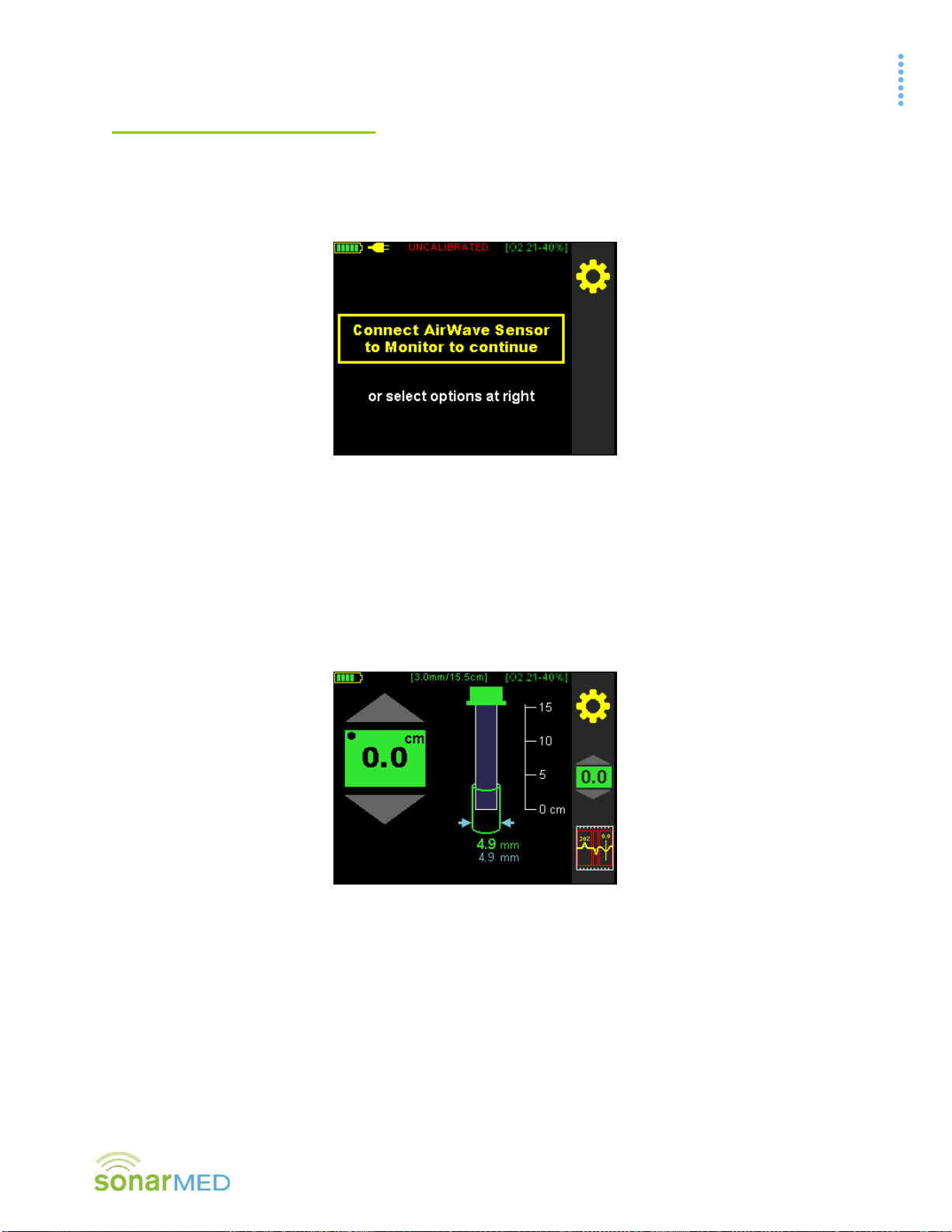
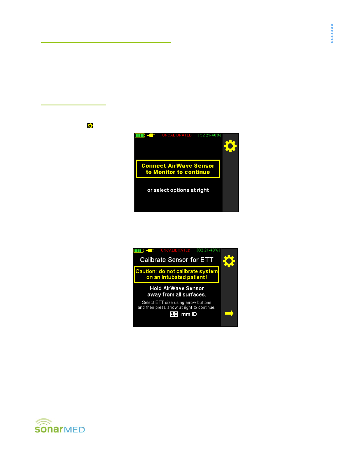
a. If the Monitor is turned on without a Sensor connected to the Monitor, the Monitor displays the screen
below (see Figure G-1). The only option is to access the Main Menu by pressing the top function key
(Gear Icon ).
Figure G-1
b. If an AirWave Sensor is connected to the Monitor the Monitor automatically recognizes the Sensor and
prompts the start of the calibration (see Figure G-2). Section G.6 - Sensor Calibration provides full
details about the calibration process.
Figure G-2
Table of contents
Popular Medical Equipment manuals by other brands

TransLite
TransLite Veinlite LED quick start guide

importvet
importvet SV-2 user manual

Fresenius Kabi
Fresenius Kabi Volumat MC Agilia Quick reference guide

Orliman
Orliman THERA GO TGO330 INSTRUCTIONS FOR USE, STORAGE AND WARRANTY

Nasco
Nasco Lifeform LF01121U instruction manual

ResMed
ResMed lumis series user guide


